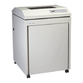
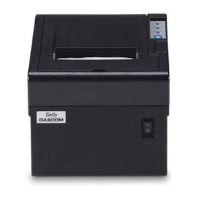
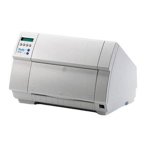
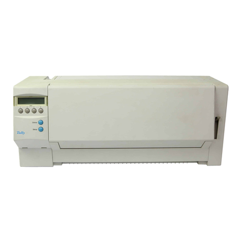
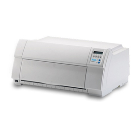
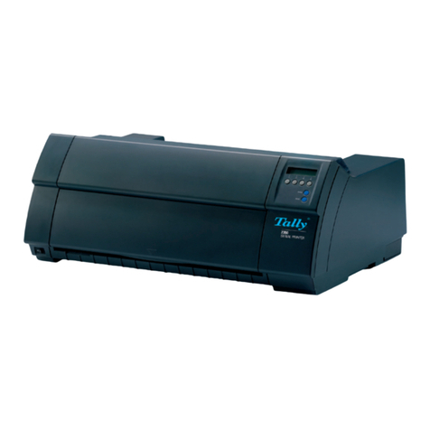
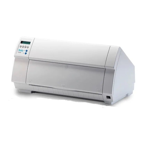
Tally T2030/24 User manual

Maintenance Manual Matrix Printer
T2030/24
T2030/9
T2130/24
T2130/9

Table of Contents
1 Introduction . . . . . . . . . . . . . . . . . . . . . . . . . . . . . . . . . . 1-1
1.1 Guide to Safety Inspections . . . . . . . . . . . . . . . . . . . . . . . . . . . . . . . . . 1-1
1.1.1 Guideline to Inspections . . . . . . . . . . . . . . . . . . . . . . . . . . . . . . . . . . . . 1-1
1.1.2 Inspection Items . . . . . . . . . . . . . . . . . . . . . . . . . . . . . . . . . . . . . . . . 1-1
1.2 Overview . . . . . . . . . . . . . . . . . . . . . . . . . . . . . . . . . . . . . . . . . . . . 1-3
1.3 Components of the Printer . . . . . . . . . . . . . . . . . . . . . . . . . . . . . . . . . . 1-5
1.3.1 Hardware Options . . . . . . . . . . . . . . . . . . . . . . . . . . . . . . . . . . . . . . . 1-6
2 Specifications . . . . . . . . . . . . . . . . . . . . . . . . . . . . . . . . 2-1
2.1 Specifications 9-needle Version . . . . . . . . . . . . . . . . . . . . . . . . . . . . . . . 2-1
2.2 Specifications 24-needle Version . . . . . . . . . . . . . . . . . . . . . . . . . . . . . . 2-6
2.3 Protective Function for Print Head Overheating . . . . . . . . . . . . . . . . . . . . . . 2-11
3 Functional Description . . . . . . . . . . . . . . . . . . . . . . . . . . . . 3-1
3.1 Activating Principles . . . . . . . . . . . . . . . . . . . . . . . . . . . . . . . . . . . . . 3-1
3.1.1 Print Head . . . . . . . . . . . . . . . . . . . . . . . . . . . . . . . . . . . . . . . . . . . 3-2
3.1.2 Carrier Drive Mechanism and Ribbon Drive Mechanism . . . . . . . . . . . . . . . . . . . . 3-3
3.1.3 Paper Feed Mechanism . . . . . . . . . . . . . . . . . . . . . . . . . . . . . . . . . . . . 3-5
3.1.4 Operation Panel . . . . . . . . . . . . . . . . . . . . . . . . . . . . . . . . . . . . . . . . 3-7
3.1.5 Auto Sheet Feeder (ASF) . . . . . . . . . . . . . . . . . . . . . . . . . . . . . . . . . . . . 3-7
3.1.6 Optional Tractor . . . . . . . . . . . . . . . . . . . . . . . . . . . . . . . . . . . . . . . . . 3-8
3.2 Installing Procedure . . . . . . . . . . . . . . . . . . . . . . . . . . . . . . . . . . . . . . 3-9
3.3 Layout of Main Parts . . . . . . . . . . . . . . . . . . . . . . . . . . . . . . . . . . . . . 3-10
4 Troubleshooting and Caring for the Printer . . . . . . . . . . . . . . . . 4-1
4.1 Troubleshooting . . . . . . . . . . . . . . . . . . . . . . . . . . . . . . . . . . . . . . . . 4-1
4.1.1 Overview . . . . . . . . . . . . . . . . . . . . . . . . . . . . . . . . . . . . . . . . . . . . 4-1
4.1.2 Diagnostic Function . . . . . . . . . . . . . . . . . . . . . . . . . . . . . . . . . . . . . . . 4-3
4.1.3 Trouble Analysis . . . . . . . . . . . . . . . . . . . . . . . . . . . . . . . . . . . . . . . . 4-10
4.1.4 Analyzing Procedure . . . . . . . . . . . . . . . . . . . . . . . . . . . . . . . . . . . . . . 4-14
4.2 Preventive Maintenance (PM) . . . . . . . . . . . . . . . . . . . . . . . . . . . . . . . . 4-38
4.2.1 Remarks on Maintenance . . . . . . . . . . . . . . . . . . . . . . . . . . . . . . . . . . . 4-38
4.2.2 Spots to be Inspected . . . . . . . . . . . . . . . . . . . . . . . . . . . . . . . . . . . . . 4-38
4.2.3 Spots to be Lubricated and Kinds of Oil to be Used . . . . . . . . . . . . . . . . . . . . . . 4-39
4.2.4 Auto Sheet Feeder (ASF) . . . . . . . . . . . . . . . . . . . . . . . . . . . . . . . . . . . . 4-45
4.2.5 Optional Tractor . . . . . . . . . . . . . . . . . . . . . . . . . . . . . . . . . . . . . . . . . 4-48
4.3 Tools for Maintenance . . . . . . . . . . . . . . . . . . . . . . . . . . . . . . . . . . . . 4-50
5 Instructions for Dissassembly and Assembly . . . . . . . . . . . . . . . 5-1
5.1 Detaching and Attaching of Parts . . . . . . . . . . . . . . . . . . . . . . . . . . . . . . 5-2
5.1.1 Knob . . . . . . . . . . . . . . . . . . . . . . . . . . . . . . . . . . . . . . . . . . . . . . 5-2
5.1.2 Access Cover Assembly and Rear Cover . . . . . . . . . . . . . . . . . . . . . . . . . . . 5-3
5.1.3 Front Cover Assembly . . . . . . . . . . . . . . . . . . . . . . . . . . . . . . . . . . . . . 5-4
5.1.4 Top Cover Assembly . . . . . . . . . . . . . . . . . . . . . . . . . . . . . . . . . . . . . . 5-7
5.1.5 Print Head (24L) . . . . . . . . . . . . . . . . . . . . . . . . . . . . . . . . . . . . . . . . 5-9

5.1.6 Head Flex Cable (24) . . . . . . . . . . . . . . . . . . . . . . . . . . . . . . . . . . . . . 5-10
5.1.7 Path Change Lever . . . . . . . . . . . . . . . . . . . . . . . . . . . . . . . . . . . . . . 5-11
5.1.8 Plate Frame Support SUB . . . . . . . . . . . . . . . . . . . . . . . . . . . . . . . . . . . 5-12
5.1.9 EMI 1 Wire, Earth PL B, Earth PL C, Earth PL (8), Earth PL (10) . . . . . . . . . . . . . . . 5-13
5.1.10 Main Logic Card (JPN) . . . . . . . . . . . . . . . . . . . . . . . . . . . . . . . . . . . . . 5-17
5.1.11 Power Supply (JPN) . . . . . . . . . . . . . . . . . . . . . . . . . . . . . . . . . . . . . . 5-19
5.1.12 Power Supply Cable . . . . . . . . . . . . . . . . . . . . . . . . . . . . . . . . . . . . . . 5-21
5.1.13 SUB PCB PL (24L) . . . . . . . . . . . . . . . . . . . . . . . . . . . . . . . . . . . . . . . 5-22
5.1.14 Tractor Unit . . . . . . . . . . . . . . . . . . . . . . . . . . . . . . . . . . . . . . . . . . . 5-24
5.1.15 Plate Frame Support . . . . . . . . . . . . . . . . . . . . . . . . . . . . . . . . . . . . . . 5-26
5.1.16 Idle Pulley Assembly . . . . . . . . . . . . . . . . . . . . . . . . . . . . . . . . . . . . . . 5-27
5.1.17 Gap Set Lever . . . . . . . . . . . . . . . . . . . . . . . . . . . . . . . . . . . . . . . . . 5-28
5.1.18 CA Motor (HB) . . . . . . . . . . . . . . . . . . . . . . . . . . . . . . . . . . . . . . . . . 5-29
5.1.19 Carrier Assembly . . . . . . . . . . . . . . . . . . . . . . . . . . . . . . . . . . . . . . . . 5-33
5.1.20 Pinch Roller (1) . . . . . . . . . . . . . . . . . . . . . . . . . . . . . . . . . . . . . . . . . 5-35
5.1.21 Gears Frame (R) . . . . . . . . . . . . . . . . . . . . . . . . . . . . . . . . . . . . . . . . 5-37
5.1.22 HP SW ASM . . . . . . . . . . . . . . . . . . . . . . . . . . . . . . . . . . . . . . . . . . 5-39
5.1.23 Gap Position Sensor . . . . . . . . . . . . . . . . . . . . . . . . . . . . . . . . . . . . . . 5-40
5.1.24 Paper Guide (H) Assembly . . . . . . . . . . . . . . . . . . . . . . . . . . . . . . . . . . . 5-41
5.1.25 Path Change Lever . . . . . . . . . . . . . . . . . . . . . . . . . . . . . . . . . . . . . . 5-43
5.1.26 Print Unit . . . . . . . . . . . . . . . . . . . . . . . . . . . . . . . . . . . . . . . . . . . . 5-45
5.1.27 Option Card . . . . . . . . . . . . . . . . . . . . . . . . . . . . . . . . . . . . . . . . . . 5-47
5.1.28 Option Flexible Cable . . . . . . . . . . . . . . . . . . . . . . . . . . . . . . . . . . . . . 5-48
5.1.29 Base Cover Assembly . . . . . . . . . . . . . . . . . . . . . . . . . . . . . . . . . . . . . 5-50
5.1.30 Paper Select Sensor . . . . . . . . . . . . . . . . . . . . . . . . . . . . . . . . . . . . . . 5-51
5.1.31 PE Sensor ASM . . . . . . . . . . . . . . . . . . . . . . . . . . . . . . . . . . . . . . . . 5-52
5.1.32 Platen Assembly . . . . . . . . . . . . . . . . . . . . . . . . . . . . . . . . . . . . . . . . 5-53
5.1.33 Paper Guide Assembly, Load Sensor . . . . . . . . . . . . . . . . . . . . . . . . . . . . . 5-55
5.1.34 Feed Roller Upper Assembly . . . . . . . . . . . . . . . . . . . . . . . . . . . . . . . . . 5-58
5.1.35 Feed Roller Lower Assembly . . . . . . . . . . . . . . . . . . . . . . . . . . . . . . . . . 5-59
5.1.36 Shaft P.C. . . . . . . . . . . . . . . . . . . . . . . . . . . . . . . . . . . . . . . . . . . . 5-61
5.1.37 Frame (L) Assembly . . . . . . . . . . . . . . . . . . . . . . . . . . . . . . . . . . . . . . 5-62
5.1.38 Frame (R) Assembly . . . . . . . . . . . . . . . . . . . . . . . . . . . . . . . . . . . . . . 5-63
5.1.39 Auto Sheet Feeder . . . . . . . . . . . . . . . . . . . . . . . . . . . . . . . . . . . . . . . 5-64
5.1.40 Side Cover L . . . . . . . . . . . . . . . . . . . . . . . . . . . . . . . . . . . . . . . . . . 5-67
5.1.41 Side Cover R . . . . . . . . . . . . . . . . . . . . . . . . . . . . . . . . . . . . . . . . . . 5-68
5.1.42 Lever Hopper, Arm Hopper . . . . . . . . . . . . . . . . . . . . . . . . . . . . . . . . . . 5-69
5.1.43 Earth ASF 2 . . . . . . . . . . . . . . . . . . . . . . . . . . . . . . . . . . . . . . . . . . 5-70
5.1.44 Latch (L) Assembly, Link (2) Assembly, Link (3) L Assembly
on the Frame (L) Assembly Side . . . . . . . . . . . . . . . . . . . . . . . . . . . . . . . . 5-71
5.1.45 Manual Guide Rail . . . . . . . . . . . . . . . . . . . . . . . . . . . . . . . . . . . . . . . 5-73
5.1.46 ASF Card Assembly . . . . . . . . . . . . . . . . . . . . . . . . . . . . . . . . . . . . . . 5-74
5.1.47 Earth ASF 1 . . . . . . . . . . . . . . . . . . . . . . . . . . . . . . . . . . . . . . . . . . 5-75
5.1.48 ASF Motor Assembly, OP Cable . . . . . . . . . . . . . . . . . . . . . . . . . . . . . . . . 5-76
5.1.49 ASF Sensor Assembly . . . . . . . . . . . . . . . . . . . . . . . . . . . . . . . . . . . . . 5-77
5.1.50 Latch (R) Assembly, Link (2) Assembly, Link (3) R Assembly
on the Frame (R) Assembly Side . . . . . . . . . . . . . . . . . . . . . . . . . . . . . . . 5-78
5.1.51 Pick Up Roller Set . . . . . . . . . . . . . . . . . . . . . . . . . . . . . . . . . . . . . . . 5-81
5.1.52 Separation Pad Holder Assembly . . . . . . . . . . . . . . . . . . . . . . . . . . . . . . . 5-83
5.1.53 Hopper Assembly, Hopper Guide . . . . . . . . . . . . . . . . . . . . . . . . . . . . . . . 5-84
5.1.54 ASF Spring Assembly . . . . . . . . . . . . . . . . . . . . . . . . . . . . . . . . . . . . . 5-86
5.1.55 Plate Pinch Roller . . . . . . . . . . . . . . . . . . . . . . . . . . . . . . . . . . . . . . . 5-87
5.1.56 Guide Pinch Roller Assembly . . . . . . . . . . . . . . . . . . . . . . . . . . . . . . . . . 5-88
5.1.57 ASF Pinch Roller, ASF Feed Roller . . . . . . . . . . . . . . . . . . . . . . . . . . . . . . 5-89
5.1.58 Frame (L) Assembly . . . . . . . . . . . . . . . . . . . . . . . . . . . . . . . . . . . . . . 5-92
5.1.59 Frame (R) Assembly . . . . . . . . . . . . . . . . . . . . . . . . . . . . . . . . . . . . . . 5-95
5.1.60 ASF HPR SW ASM . . . . . . . . . . . . . . . . . . . . . . . . . . . . . . . . . . . . . . . 5-99
5.1.61 Optional Tractor . . . . . . . . . . . . . . . . . . . . . . . . . . . . . . . . . . . . . . . . . 5-101
5.1.62 Manual Guide Dual Assembly . . . . . . . . . . . . . . . . . . . . . . . . . . . . . . . . . 5-103
5.1.63 Cover L Dual . . . . . . . . . . . . . . . . . . . . . . . . . . . . . . . . . . . . . . . . . . 5-104
5.1.64 Cover R Dual . . . . . . . . . . . . . . . . . . . . . . . . . . . . . . . . . . . . . . . . . . 5-105
5.1.65 Card Holder Dual Assembly . . . . . . . . . . . . . . . . . . . . . . . . . . . . . . . . . . 5-106
5.1.66 2nd TR Switch Assembly . . . . . . . . . . . . . . . . . . . . . . . . . . . . . . . . . . . . 5-107
5.1.67 Motor Base Dual Assembly . . . . . . . . . . . . . . . . . . . . . . . . . . . . . . . . . . . 5-108
5.1.68 Dual Rack, Rack Lever Dual . . . . . . . . . . . . . . . . . . . . . . . . . . . . . . . . . . 5-109
5.1.69 Tractor Unit . . . . . . . . . . . . . . . . . . . . . . . . . . . . . . . . . . . . . . . . . . . 5-111
5.1.70 Frame (L) Assembly . . . . . . . . . . . . . . . . . . . . . . . . . . . . . . . . . . . . . . 5-112
5.1.71 Frame (R) Assembly . . . . . . . . . . . . . . . . . . . . . . . . . . . . . . . . . . . . . . 5-114
5.1.72 Serial Interface Option (RS-232C) . . . . . . . . . . . . . . . . . . . . . . . . . . . . . . . 5-116
6 Adjustments and Inspections . . . . . . . . . . . . . . . . . . . . . . . . 6-1
6.1 Adjusting Gap Print Head – Platen Assembly . . . . . . . . . . . . . . . . . . . . . . . . 6-1
6.2 Setting Basical Top Margin and L/R Adjustment . . . . . . . . . . . . . . . . . . . . . . 6-4
6.3 CSR (Customer Service Representative) Mode . . . . . . . . . . . . . . . . . . . . . . . 6-5
6.3.1 L/R Alignment P.LRadj . . . . . . . . . . . . . . . . . . . . . . . . . . . . . . . . . . . . . 6-6
6.3.2 NVRAM DUMP . . . . . . . . . . . . . . . . . . . . . . . . . . . . . . . . . . . . . . . . . 6-8
6.3.3 Other Setting . . . . . . . . . . . . . . . . . . . . . . . . . . . . . . . . . . . . . . . . . . 6-8
6.3.4 Sensor Test . . . . . . . . . . . . . . . . . . . . . . . . . . . . . . . . . . . . . . . . . . . 6-9
7 Spare Parts and Schematics . . . . . . . . . . . . . . . . . . . . . . . . 7-1
7.1 Spare Parts . . . . . . . . . . . . . . . . . . . . . . . . . . . . . . . . . . . . . . . . . . 7-2
7.1.1 Printer Unit – Assembly 1 . . . . . . . . . . . . . . . . . . . . . . . . . . . . . . . . . . . . 7-2
7.1.2 Printer Unit – Assembly 2 . . . . . . . . . . . . . . . . . . . . . . . . . . . . . . . . . . . . 7-4
7.1.3 Printer Unit – Assembly 3 . . . . . . . . . . . . . . . . . . . . . . . . . . . . . . . . . . . . 7-6
7.1.4 Printer Unit – Assembly 4 . . . . . . . . . . . . . . . . . . . . . . . . . . . . . . . . . . . . 7-8
7.1.5 Printer Unit – Assembly 5 . . . . . . . . . . . . . . . . . . . . . . . . . . . . . . . . . . . . 7-10
7.1.6 Printer Unit – Assembly 6 . . . . . . . . . . . . . . . . . . . . . . . . . . . . . . . . . . . . 7-12
7.1.7 Printer Unit – Assembly 7 . . . . . . . . . . . . . . . . . . . . . . . . . . . . . . . . . . . . 7-14
7.1.8 Auto Sheet Feeder (ASF) – Assembly 1 . . . . . . . . . . . . . . . . . . . . . . . . . . . . 7-16
7.1.9 Auto Sheet Feeder (ASF) – Assembly 2 . . . . . . . . . . . . . . . . . . . . . . . . . . . . 7-18
7.1.10 Auto Sheet Feeder (ASF) – Assembly 3 . . . . . . . . . . . . . . . . . . . . . . . . . . . . 7-20
7.1.11 Auto Sheet Feeder (ASF) – Assembly 4 . . . . . . . . . . . . . . . . . . . . . . . . . . . . 7-22
7.1.12 Auto Sheet Feeder (ASF) – Assembly 5 . . . . . . . . . . . . . . . . . . . . . . . . . . . . 7-24
7.1.13 Optional Tractor – Assembly 1 . . . . . . . . . . . . . . . . . . . . . . . . . . . . . . . . . 7-26
7.1.14 Optional Tractor – Assembly 2 . . . . . . . . . . . . . . . . . . . . . . . . . . . . . . . . . 7-28
7.2 Wiring Diagrams . . . . . . . . . . . . . . . . . . . . . . . . . . . . . . . . . . . . . . . . 7-30
7.3 Schematics . . . . . . . . . . . . . . . . . . . . . . . . . . . . . . . . . . . . . . . . . . 7-42
7.3.1 T2130/24 Block Diagram . . . . . . . . . . . . . . . . . . . . . . . . . . . . . . . . . . . . 7-42
7.3.2 Optional Tractor Block Diagram . . . . . . . . . . . . . . . . . . . . . . . . . . . . . . . . 7-43
7.3.3 Auto Sheet Feeder Block Diagram . . . . . . . . . . . . . . . . . . . . . . . . . . . . . . . 7-44
7.3.4 Serial Interface Option Block Diagram . . . . . . . . . . . . . . . . . . . . . . . . . . . . . 7-45
7.3.5 Main Card – Logic (CPU/ROM/RAM/Gate-Array) . . . . . . . . . . . . . . . . . . . . . . . 7-46
7.3.6 Main Card – Option & Sensor Connector . . . . . . . . . . . . . . . . . . . . . . . . . . . . 7-47
7.3.7 Main Card – Interface Connector . . . . . . . . . . . . . . . . . . . . . . . . . . . . . . . . 7-48
7.3.8 Main Card – CA & LF Motor Driver . . . . . . . . . . . . . . . . . . . . . . . . . . . . . . . 7-49
7.3.9 Sub24 Card . . . . . . . . . . . . . . . . . . . . . . . . . . . . . . . . . . . . . . . . . . . 7-50
7.3.10 Panel Card . . . . . . . . . . . . . . . . . . . . . . . . . . . . . . . . . . . . . . . . . . . 7-51
7.3.11 Power Supply Card . . . . . . . . . . . . . . . . . . . . . . . . . . . . . . . . . . . . . . . 7-52
7.3.12 SIF Card . . . . . . . . . . . . . . . . . . . . . . . . . . . . . . . . . . . . . . . . . . . . 7-53

1 Introduction
1.1
Guide to Safety
Inspections Turn OFF the power of the machine and unplug all the power cords before starting in-
spections.
Ensure that all safety requirements are satisfied.
1.1.1
Guideline to Inspections This guideline is provided to check if the machine is in a dangerous status or not. A
safety mechanism or caution label is needed to prevent the owner, operators, or ser-
vice personnel from sustaining injuries. This check list shows these items. Should any
dangers arise that are not listed here, you must determine whether or not it is safe to
continue operating the machine.
Notes:
Electric Factors
– Is the primary side power shortcircuited to the machine frame?
– Is the covering of the cable wire peeled off? Is the cable correctly secured with
cable ties or clamps?
Mechanical Factors
– Are there any burrs, sharp edges, etc. which may be harmful?
Other Factors
Are there any explosive parts, such as inflated capacitors, etc.?
Are any nonspecified chemicals, solvents, etc. being used?
Danger: For inspections, be sure to turn OFF the power switch and then unplug the
power cord.
1.1.2
Inspection Items Open the cover.
– Are any cables damaged, or may be harmful?
– Are any cable coverings worn away, frayed, being pinched by the cover or other
parts or are all cables secured correctly with cable ties, clamps, etc?
– Is the power turned ON/OFF correctly in the electric and mechanical aspects?
Danger: Is the power cord unplugged?
– Is the power cord correctly secured with cord clamps, etc.?
– Is the covering cord damaged?
– Is a mold type plug (conforming to standards) attached?
– Confirm the insulation between the plug flat pins and the machine frame.
STOP
STOP
Introduction Guide to Safety Inspections
1-1

Are the following labels applied?
[1] Indication of a danger spot
or
[2] Indication of a heated-up spot
Confirm during preventive maintenance that safety labels are applied at the positions
shown in the figure below.
Safety Labels
[1] Indication of a danger spot
[2] Indication of a heated-up spot
* The GND mark is applied at the “A” spot.
Fig. 1-1: Safety Labels
4
400 V
“A” spot
Guide to Safety Inspections Introduction
1-2

1.2
Overview When attached to a network, this printer can be used as an output device to print
Fonts and Graphics using the dot-matrix impact method.
Fig. 1-2: Front Side of the Printer
Fig. 1-3: Rear Side of the Printer
Paper Extension Trays
Access Cover
Paper Feed Knob
Power
Switch
Option Connectors
Paper Type Selection Lever
Front Cover
Right Paper
Guide
Cut Sheet Paper
Insert Guide
Left Paper
Guide
Operation Panel
Paper Tray
Latch Lever
Interface Connector
Power Inlet
Latch Lever
Rear Cover
Perforated Line Cutter
Paper Thickness
Adjustment Lever
Introduction Overview
1-3

Fig. 1-4: Printer With Auto Sheet Feeder (ASF)
Fig. 1-5: Printer With Optional Tractor
Fig. 1-6: Serial Interface Option
Auto Sheet Feeder
(ASF)
Optional Tractor
Serial Interface Option
Overview Introduction
1-4

1.3
Components of
the Printer
Fig. 1-7: Components of the Printer
Main
Logic
Board
I/F Connector
Option Card
CA Motor
LF Motor
Load Sensor, PE Sensor
Asm, Paper Select Sensor
Power Supply Sub PCB PL Print Head
Home Position
Sensor
SW
Operator’s
Panel
Introduction Components of the Printer
1-5

1.3.1
Hardware Options The following three items are hardware options for this printer.
Auto Sheet Feeder (ASF)
The ASF is a device to feed cut sheet paper, sheet by sheet, by controls from the
printer. Fig. 1-8 shows the Auto Sheet Feeder (ASF).
Fig. 1-8: Auto Sheet Feeder (ASF)
Optional Tractor
The Optional Tractor has the same function as the printer’s built-in tractor. By install-
ing this device, two types of continuous form feed paper can be used with the paper
remaining loaded. Fig. 1-9 shows the Optional Tractor.
Fig. 1-9: Optional Tractor
Manual Insert Guide
Auto Sheet Feeder
Hopper Guides
Optional Tractor Front Cover
Front Cover
Components of the Printer Introduction
1-6

2 Specifications
2.1
Specifications 9-Needle
Version
Printer Specifications
Print head Quantity 9 needles
Diameter 0.30 mm
Pitch of needles 1/72 inch
Copies 1 + 5
Lifetime > 200 mill. dots/pin (refurbishment is not possible)
Print speed HS Draft bidirectional 360 cps at 10.0 cpi
320 cps at 12.0 cpi
400 cps at 15.0 cpi
230 cps at 17.1 cpi
270 cps at 20.0 cpi
Draft bidirectional 270 cps at 10.0 cpi
320 cps at 12.0 cpi
270 cps at 15.0 cpi
230 cps at 17.1 cpi
270 cps at 20.0 cpi
NLQ unidirectional 65 cps at 10.0 cpi 2 pass paper shift
78 cps at 12.0 cpi 2 pass paper shift
65 cps at 15.0 cpi 2 pass paper shift
73 cps at 17.1 cpi 2 pass paper shift
132 cps at 20.0 cpi 2 pass paper shift
Tabulation speed print speed
Print densities 5.0/6.0/7.5/8.6/10.0/12.0/15.0/17.1/20.0 cpi
Print attributes Double width, italics, right justification, shadowed, auto centered, double height,
in all character pitches bold, proportionally spaced, underlined, overlined, superscript, subscript
Page performance 300 pph
ECMA 132
Specifications Specifications 9-Needle Version
2-1

Print positions T2030/T2130 80/136 characters at 10.0 cpi
96/163 characters at 12.0 cpi
120/204 characters at 15.0 cpi
136/232 characters at 17.1 cpi
160/272 characters at 20.0 cpi
Line spacing 3/4/6/8/12 lpi
Character size 3.20 mm high (includes descenders)
1.90 mm wide (full width characters)
Character sets IBM-PC world trade and IBM-PC US trade. Epson character generator
Up to 21 national character sets according to
US ASCII PC-Norwegian E-Spanish2
French UK E-L.American
Italian German E-Korean
Norwegian Swedish E-Legal
Portuguese Spanish E-Danish2
E-French E-US ASCII Codepage 437
E-U.K. E-German 850
E-Swedish1 E-Danish1 860
E-Spanish1 E-Italian 863
E-Norwegian E-Japanese 865
standards.
The character generators exist in DPQ and in NLQ. The two resident NLQ
character fonts are Quadrato and Courier.
Dot densities (horizontal) DPQ 120 dots per inch at 10 cpi
NLQ 240 dots per inch at 10 cpi
Dot densities (vertical) 144 dots per inch
Graphic densities Horizontal 60 dots per inch
72 dots per inch
80 dots per inch
90 dots per inch
120 dots per inch
144 dots per inch
240 dots per inch
Vertical 144 dots per inch
Slew speed 5 inches per second
Reversal is limited to 22 inches
Specifications 9-Needle Version Specifications
2-2

Ribbons The standard black ribbon provides a minimum of 4 million legible draft characters
before degradation occurs.
Paper specification The printer handles single sheets, multipart forms and continuous sprocket forms.
Single sheets may be inserted manually from the front using the cut sheet paper
insert guide or automatically using the cut sheet feeder ASF. Continuous forms
stationary may remain present in tractors. Paper with dark backside, for example
black or spreckled black, must be tested!
Tractor + Opt. Tractor Paper: Single part Multipart forms
Insertion from the front weight 60 g/m2to 90 g/m21. sheet 45 g/m2to 65 g/m2,
copies 45 g/m2to 56 g/m2
last sheet 45 g/m2- 65 g/m2
width (T2030) 3 inches to 10 inches 3 inches to 10 inches
(76 mm to 254 mm) (76 mm to 254 mm)
width (T2130) 3 inches to 16.5 inches 3 inches to 16.5 inches
(76 mm to 420 mm) (76 mm to 420 mm)
length 3 inches to 22 inches 3 inches to 22 inches
(76 mm to 559 mm) (76 mm to 559 mm)
thickness Max. 0.019 inch (0.5 mm)
copies 1 + 5
Friction from front Paper: Single part Multipart forms
cut sheet paper
insert guide weight 60 g/m2to 120 g/m21. sheet 50 g/m2to 60 g/m2,
copies 45 g/m2to 56 g/m2
last sheet 50 g/m2- 60 g/m2
width (T2030) 3 inches to 8.6 inches 3 inches to 8.6 inches
(76 mm to 220 mm) (76 mm to 220 mm)
width (T2130) 3 inches to 16.5 inches 3 inches to 16.5 inches
(76 mm to 420 mm) (76 mm to 420 mm)
length 3 inches to 22 inches Min. 3 inches
(76 mm to 559 mm) (76 mm)
thickness Max. 0.019 inch (0.5 mm)
copies 1 + 5
Max. form thickness 0.5 mm
Automatic sheet feeder Paper: Single part Multipart forms
ASF (option) weight 60 g/m2to 80 g/m21. sheet 50 g/m2to 60 g/m2,
copies 45 g/m2to 56 g/m2
last sheet 50 g/m2- 60 g/m2
width (T2030) 3 inches to 8.6 inches 4 inches to 8.5 inches
(76 mm to 220 mm) (100 mm to 216 mm)
width (T2130) 3 inches to 16.5 inches 4 inches to 14.3 inches
(76 mm to 420 mm) (100 mm to 364 mm)
length 1st bin 3 inches to 22 inches 4 inches to 14 inches
(76 mm to 559 mm) (100 mm to 356 mm)
thickness Max. 0.019 inch (0.5 mm)
copies 1 + 5
Specifications Specifications 9-Needle Version
2-3

Physical characteristics
Noise Tractor <55 dB (A)
Sheet feeder <55 dB (A)
Measured with draft characters according to ISO
standard 7779 in bystander position.
Dimensions Approximate physical dimensions
with ASF1
width (T2030) 485 mm
width (T2130) 625 mm
depth 245 mm 380 mm
height 206 mm 380 mm
weight (T2030) 9 kg
weight (T2130) 11 kg
Power One of the following secondary power supply is installed:
A) AC 110 – 120 V 50/60 Hz
B) AC 220 – 240 V 50/60 Hz
Power consumption Printing: <60 W
Stand by: <10 W
Heat dissipation Printing: 60 W
Stand by: 10 W
Temperature and humidity
Operating Temperature +10 °C to +40 °C (temp. rise less than 11 °C per hour)
Humidity 20 % to 80 % relative humidity, non-condensing
Altitude Sea level to 10.000 ft
Climate According to DIN 50019/T3 R12
Storage Temperature -10 °C to +50 °C
Humidity 10 % to 80 % relative humidity, non-condensing
Climate According to DIN 50019/T3 R14
Transport Temperature -30 °C to +70 °C
Humidity 10 % to 90 % relative humidity
Altitude Sea level to 40.000 ft
Specifications 9-Needle Version Specifications
2-4

Mechanical Stability
Vibration Operation Transport (no pack.)
on three axes on three axes
Frequency range 5 Hz to 150 Hz 5 Hz to 150 Hz
Acceleration ampl. 5 m/s 5 m/s
Displacement ampl. 0.035 mm 0.035 mm
Exposure time (total) 1.5 hours 1.5 hours
Bump Operation Transport (no pack.)
on three axes on three axes
Frequency range 1 Hz to 3 Hz 1 Hz to 3 Hz
Acceleration ampl. 10 m/s 50 m/s
Cycles in z-axis 1000 5000
Cycles in x/y-axis 1000 1000
Reliability MTTR 15 minutes (by change of modules)
MTBF 10.000 hours by 25% duty cycle
Electrical Conditions
Electrostatic discharge Test procedure IEC 801 level 3
Peak voltage 8,000 V without malfunction
Peak voltage 15,000 V without damage
Electromagnetic Test procedure see Certifications
interference
EMI Susceptibility Transient energy loss Printer remains fully operational when supply is interrupted
for half a cycle once in 10 second.
Overvoltage protection Low energy / high frequency
Pulse characteristics Rise time 5 ns
Pulse width 100 ns
Energy 2 mJ
Voltage 2000 V
Overvoltage protection High energy / low frequency
Pulse characteristics Rise time 150 ns sym.
300 ns asym.
Pulse width 50 µs
Energy 2 J
Voltage 1000 V sym.
2000 V asym.
Certifications UL 1950, First Edition / CSA-C22.2 No.950-M89 / FCC Regulation, Port 15,
Subp.B, Class B / DIN VDE 0805/05.90 +A1/11.91 /
EN 60950:1988 +A1:1990 + A2:1991 (IEC 950: 1986 - 1.Edition modified) /
VDE/F VDE 0878 Part 3/11.89 combined with Verfügung 1046/1984
(Post und Telekommunikation) / EN 55022: 1987 /
Specifications Specifications 9-Needle Version
2-5

2.2
Specifications 24-Needle
Version
Printer Specifications
Print head Quantity 24 needles, 2 rows staggered
Diameter 0.20 mm
Pitch of needles 1/180 inch
Copies 1 + 3
Lifetime > 200 mill. dots/pin (refurbishment is not possible)
Print speed ±7 % (depend of character matrix)
Fast Draft bidirectional 330 cps at 10.0 cpi
Draft bidirectional 250 cps at 10.0 cpi
270 cps at 12.0 cpi
170 cps at 15.0 cpi
193 cps at 17.1 cpi
LQ bidirectional 70 cps at 10.0 cpi
90 cps at 12.0 cpi
113 cps at 15.0 cpi
128 cps at 17.1 cpi
150 cps at 20.0 cpi
Tabulation speed Print speed
Print densities 5.0/6.0/7.5/8.6/10.0/12.0/15.0/17.1/20.0 cpi
Print attributes Double width, italics, right justification, shadowed, auto centered, double height,
in all character pitches bold, proportionally spaced, underlined, overlined, superscript, subscript
Page performance 300 pph
ECMA 132
Specifications 24-Needle Version Specifications
2-6

Print positions T2030/T2130
80/136 characters at 10.0 cpi
96/163 characters at 12.0 cpi
120/204 characters at 15.0 cpi
136/232 characters at 17.1 cpi
160/272 characters at 20.0 cpi
Line spacing 3/4/6/8/12 lpi
Character size 3.20 mm high (includes descenders)
1.90 mm wide (full width characters)
Character sets IBM-PC world trade and IBM-PC US trade.
Epson character generator (128 characters italics).
Up to 25 national character sets according to
PC Norwegian E-German Codepage 437
US ASCII E-U.K. 850
U.K. E-Danish 1 860
French E-Swedish 863
German E-Italian 865
Italian E-Spanish 1
Swedish E-Japanese
Norwegian E-Norwegian
Spanish E-Danish 2
Portuguese E-Spanish 2
E-US ASCII E-Latin american
E-French E-Korea
E-Legal
standards.
The character generators exist in DPQ, NLQ and in LQ. The resident NLQ and
LQ character fonts are Courier, Prestige, OCR A, OCR B, Roman, Sans Serif and
Script. The character width are compatible to the Epson Fonts.
Dot densities Draft 120 dots per inch at 10 cpi
(horizontal) LQ 360 dots per inch at 10 cpi
Dot densities 180 dots per inch
(vertical)
Graphic densities Horizontal 60 dots per inch
72 dots per inch
80 dots per inch
90 dots per inch
120 dots per inch
180 dots per inch
240 dots per inch
360 dots per inch
Vertical 180 dots per inch
Slew speed 5 inches per second
Specifications Specifications 24-Needle Version
2-7

Ribbons The printer uses a cassette fabric ribbon that can be changed by the operator.
The standard black ribbon provides a minimum of 4 million (T2030/T2130) legible
draft characters before degradation occurs.
Paper specification The printer handles single sheets, multipart forms and continuous sprocket forms.
Single sheets may be inserted manually from the front using the cut sheet paper
insert guide or automatically using the cut sheet feeder ASF. Continuous forms
stationary may remain present in tractors.
Paper with dark backside, for example black or spreckled black, must be tested!
Tractor + Opt. Tractor Paper: Single part Multipart forms
Insertion from the front weight 60 g/m2to 90 g/m21. sheet 45 g/m2to 65 g/m2,
copies 45 g/m2to 56 g/m2
last sheet 45 g/m2- 65 g/m2
width (T2030) 3 inches to 10 inches 3 inches to 10 inches
(76 mm to 254 mm) (76 mm to 254 mm)
width (T2130) 3 inches to 16.5 inches 3 inches to 16.5 inches
(76 mm to 420 mm) (76 mm to 420 mm)
length 3 inches to 22 inches 3 inches to 22 inches
(76 mm to 559 mm) (76 mm to 559 mm)
thickness Max. 0.019 inch (0.5 mm)
copies 1 + 3
Friction, Paper: Single part Multipart forms
Insertion from front
cut sheet paper weight 60 g/m2to 120 g/m21. sheet 50 g/m2to 60 g/m2,
insert guide copies 45 g/m2to 56 g/m2
last sheet 50 g/m2- 60 g/m2
width (T2030) 3 inches to 8.6 inches 3 inches to 8.6 inches
(76 mm to 220 mm) (76 mm to 220 mm)
width (T2130) 3 inches to 16.5 inches 3 inches to 16.5 inches
(76 mm to 420 mm) (76 mm to 420 mm)
length 3 inches to 22 inches 3 inches to 22 inches
(76 mm to 559 mm) (76 mm to 559 mm)
thickness 0.019 inch (0.5 mm)
copies 1 + 3
Automatic sheet feeder Paper: Single part Multipart forms
ASF (option) weight 60 g/m2to 80 g/m21. sheet 50 g/m2to 60 g/m2,
copies 45 g/m2to 56 g/m2
last sheet 50 g/m2- 60 g/m2
width (T2030) 3 inches to 8.6 inches 3 inches to 8.6 inches
(76 mm to 220 mm) (76 mm to 220 mm)
width (T2130) 3 inches to 16.5 inches 3 inches to 16.5 inches
(76 mm to 420 mm) (76 mm to 420 mm)
length 1st bin 3 inches to 22 inches 3 inches to 22 inches
(76 mm to 559 mm) (76 mm to 559 mm)
thickness Max. 0.019 inch (0.5 mm)
copies 1 + 3
Specifications 24-Needle Version Specifications
2-8

Physical characteristics
Noise Tractor <55 dB (A)
Sheet feeder <55 dB (A)
Measured with draft characters according to ISO
standard 7779 in bystander position.
Dimensions Approximate physical dimensions
with ASF
width (T2030) 485 mm
width (T2130) 625 mm
depth 245 mm 380 mm
height 206 mm 380 mm
weight (T2030) 9 kg
weight (T2130) 11 kg
Power One of the following secondarypower supply is installed:
A) AC 110 – 120 V 50/60 Hz
B) AC 220 – 240 V 50/60 Hz
Power consumption Printing: <60 W
Stand by: <10 W
Heat dissipation Printing: 60 W
Stand by: 10 W
Temperature and humidity
Operating Temperature +10 °C to +40 °C (temp. rise less than 11 °C per hour)
Humidity 20 % to 80 % relative humidity, non-condensing
Altitude Sea level to 10,000 ft
Climate According to DIN 50019/T3 R12
Storage Temperature -10 °C to +50 °C
Humidity 10 % to 80 % relative humidity, non-condensing
Climate According to DIN 50019/T3 R14
Transport Temperature -30 °C to +70 °C
Humidity 10 % to 90 % relative humidity
Altitude Sea level to 40,000 ft
Specifications Specifications 24-Needle Version
2-9

Mechanical Stability
Vibration Operation Transport (no pack.)
on three axes on three axes
Frequency range 5 Hz to 150 Hz 5 Hz to 150 Hz
Acceleration ampl. 5 m/s 5 m/s
Displacement ampl. 0.035 mm 0.035 mm
Exposure time (total) 1.5 hours 1.5 hours
Bump Operation Transport (no pack.)
on three axes on three axes
Frequency range 1 Hz to 3 Hz 1 Hz to 3 Hz
Acceleration ampl. 10 m/s 50 m/s
Cycles in z-axis 1000 5000
Cycles in x/y-axis 1000 1000
Transport safety The packaged printer is dropped from a height of 30 inches
- on each of 6 side walls
- on four bottom corners
Reliability MTTR 15 minutes (by change of modules)
MTBF 10.000 hours by 25% duty cycle
Electrical Conditions
Electrostatic discharge Test procedure IEC 801 level 3
Peak voltage 8,000 V without malfunction
Peak voltage 15,000 V without damage
Electromagnetic Test procedure see Certifications
interference
EMI Susceptibility Transient energy loss Printer remains fully operational when supply is interrupted
for half a cycle once in 10 second.
Overvoltage protection Low energy / high frequency
Pulse characteristics Rise time 5 ns
Pulse width 100 ns
Energy 2 mJ
Voltage 2000 V
Overvoltage protection High energy / low frequency
Pulse characteristics Rise time 150 ns sym.
300 ns asym.
Pulse width 50 µs
Energy 2 J
Voltage 1000 V sym.
2000 V asym.
Certifications UL 1950, First Edition / CSA-C22.2 No.950-M89 / FCC Regulation, Port 15,
Subp.B, Class B / DIN VDE 0805/05.90 +A1/11.91 /
EN 60950:1988 +A1:1990 + A2:1991 (IEC 950: 1986 - 1.Edition modified) /
VDE/F VDE 0878 Part 3/11.89 combined with Verfügung 1046/1984
(Post und Telekommunikation) / EN 55022: 1987 /
Specifications 24-Needle Version Specifications
2-10
Other manuals for T2030/24
1
This manual suits for next models
3
Table of contents
Other Tally Printer manuals

Tally
Tally T6140 User manual

Tally
Tally T2033S User manual

Tally
Tally T2040 User manual

Tally
Tally Xpress T8016 User manual

Tally
Tally XPRESS T9412i Installation instructions

Tally
Tally T9006 User manual

Tally
Tally T8024 User manual

Tally
Tally T9112 User manual

Tally
Tally T2140 User manual

Tally
Tally T8106 User manual

Tally
Tally T3016 User manual

Tally
Tally T6215 User manual

Tally
Tally T2265 SprintPro User manual

Tally
Tally t2145 User manual

Tally
Tally T2380 User manual

Tally
Tally T6215 User manual

Tally
Tally T9020 User manual

Tally
Tally T9408 User manual

Tally
Tally Tally Mono Laser T9220 User manual

Tally
Tally T2040 User manual