manuals.online logo
Brands
  1. Home
  2. •
  3. Brands
  4. •
  5. TANDBERG
  6. •
  7. Conference System
  8. •
  9. TANDBERG T1 Assembly instructions

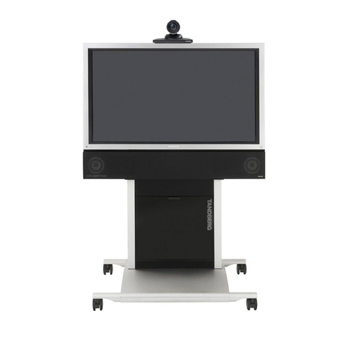
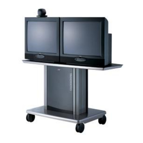
TANDBERG T1 Assembly instructions

3Mounting the bottom module to the foot module to establish the base.
MOUNTING THE BASE:
1. Remove the four nuts at the foot
module
2. Grab the bottom module and lift it
up to place the bottom module on
the foot plate
3. When looking down through the
bottom module you can see the
four screws at the foot module
4. Make sure these screws hits the
corresponding holes underneath
the bottom module.
5. Fasten the four nuts as described
and illustrated to the right.
PERSON 1: Grab and lift here
PERSON 2: Grab
and lift here
The illustration shows the standalone foot module.
The wall mounting foot module is mounted in the
same way.
PRECAUTIONS
Please follow the steps in this installation guide when unpacking and
assembling the TANDBERG T1.
A minimum of four (4) people are required during the installation of the
TANDBERG T1.
s The monitor box requires four (4) people to lift
s The bottom module requires two (2) people to lift
Weights of the different units (package included):
s Monitor box: 110 kg / 243 lbs
s Bottom module: 40 kg / 88 lbs
s Foot module box: 25 kg / 55 lbs
s Accessories + camera + grille boxes: 7 kg / 15 lbs
UNPACKING THE SYSTEM AT THE DESTINATION
It is highly recommended to start unpacking and assembling of the
TANDBERG T1 at the place where the TANDBERG T1 is to be used.
Check the dimensions of the lift if you need to use a lift for the transportation.
Outer dimensions and total weight of the main unit (package included):
s Height: 145cm/57.1in
s Width: 76cm/29.9in
s Length: 170cm/66.9in
s Weight: 182kg/401lbs
NOTE! If it is not possible to bring the main unit to the destination, follow
step 1–2 and bring the smaller units to the destination.
NOTE! The floor must be in level.
ROOM GUIDELINES
Room guidelines are described in the T1 Administrator Guide.
USER DOCUMENTATION
The user documentation for TANDBERG products is available on the
TANDBERG web site: http://www.tandberg.com/docs
DIMENSIONS
The unit has the following dimensions:
s Height: 167cm/65.7in
s Width: 153cm/60.3in
s Depth: Floor stand: 66cm/26in
Wall mount, with short bracket: 44.7cm/17.6in
Wall mount, with long bracket: 52.2cm/20.6in
TANDBERG T1 is delivered with:
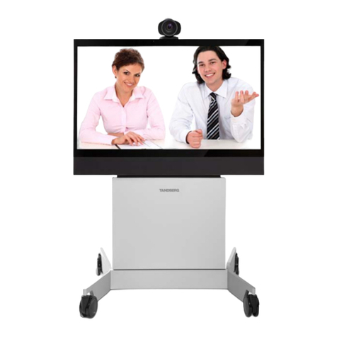
Monitor box
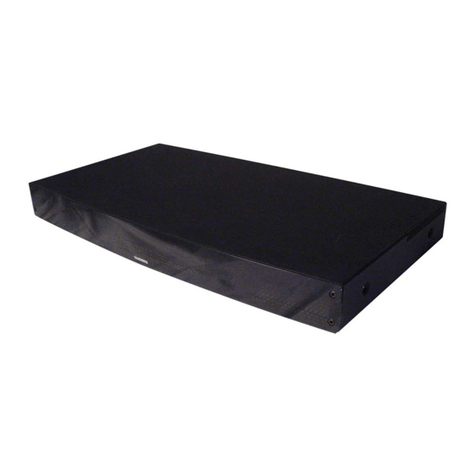
Bottom module
Foot module box (standalone/wall mount)
Grille box
TANDBERG PrecisionHD 1080p camera
Accessories box
s Microphones, 3 pcs.
s Remote Control (including 4 AAA batteries)
s Spanner, 13 mm
s Gloves, 3 pairs
s TANDBERG Cloth
Installing the TANDBERG T1
www.tandberg.com
Unpacking and assemble the TANDBERG T1
1Unpacking the foot module and the power cable
FOOT MODULE (25kg/55lbs)
1. Open the snap lockers
2. Lift out the foot module box
117098.03 MAY 2009
POWER CABLE
The power cable is found
to the left of the foot
module box in the front.
MONITOR BOX
(110kg/243lbs)
2Unpacking the unit.
CAUTION
HEAV Y
AND
BULK Y
REQUI RES :
4 PEOPLE T O
LIFT
CAUTION
HEAV Y
AND
BULK Y
REQUI RES :
2 PEOPLE T O
LIFT
STANDALONE FOOT
WALL MOUNTING
FOOT
ACCESSORIES TO THE FOOT MODULE
s Allen key
s Orange wrench for levelling adjustment
s Wall brackets (wall mounting only)
s Spacer (wall mounting only)
s Screws and bolts
Front side
Front side
Page 1
BOTTOM MODULE
(40kg/88lbs)
Lift out to open
the snap lockers
!
"
####$%&
####'()*
+
,
-./0123
4
1
!!!!5@
6
7
8
####9:;
####<=>
2#
####-./ 3
####?@A
####BCD
####EFGH
ACCESSORIES BOX
Wrench, key lock tool, screws, gloves,
microphones, remote control and
TANDBERG cloth.
The illustration shows
a cross section of the
base (bottom module
and foot module)
Fasten the 2 nuts
from the outside
Fasten the 2 nuts
from the outside
Outer cover
Camera box
Grille box
Accessories box
Foam for protection
of bottom module
Bottom module
Monitor box
1. Place the unit on a stable surface.
2. Open the snap lockers to remove
outer cover.
3. Locate the different parts.
4. Lift out the grille box, accessories
box and the camera box.
5. Remove the packaging above and
around the bottom module and
monitor box.
Lift out to open
the snap lockers
4Key lock and levelling adjustment
KEY LOCK
Place the orange key on the key
lock and turn clock-wise to lock,
counter clock-wise to unlock
LEVELLING ADJUSTMENT
Place the orange wrench on the foot
wheel (under the foot plate) and pull
to adjust up. Use the opposite side
of the tool to adjust down.
Lock
Unlock
The height adjustment tool is found in
the foot module box. The key lock tool
is found in the accessories box.
1. Locate the top cover on
the monitor and open it
2. Locate the camera
cable and connect the
HDMI and the RJ45
connectors.
3. Hold the camera upside
down and carefully place
the camera into place
7Connecting cables from the codec to the monitor
Locate the cables in the bottom module and connect them as described
in the illustration:
1. HDMI cable
2. 9 pin D-SUB cable
3. 15 pin D-SUB cable
4. Power cable
6Unpacking the Monitor box and mounting the monitor to the base
5Wall mounting the unit
The wall mounting brackets, bracket spacer, Allen
key and screws are found in the foot module box.
Space bracket: To be used between the
bottom module and the wall bracket
Wall brackets: Choose the short or long
wall bracket based on the distance
between the bottom module and the wall.
NOTE! Requires 4 people
and lifting straps to lift.
LIFTING STRAPS INCLUDED
The lifting straps are found
in the box, together with the
monitor, ready for use.
NOTE! The straps are not fixed
to the monitor. Be careful when
lifting the monitor so the straps
do not slide during the lifting
operation.
D-SUB&15Power HDMI&1 D-sub&9
Assemble the TANDBERG T1
www.tandberg.com 117098.03 MAY 2009
Page 2
11 Connect cables on the rear side
Locate and connect the cables which are lead out of the system at
the rear side:
1. Ethernet cable
2. PC cable
3. Microphone
4. Power cable
Ethernet cable
PC cable
Microphone cable
Power cable
10 Mounting the grilles in front and finishing up
1. Snap on the top grille
2. Close the top cover
3. Snap on the speaker grille
4. Remove the plastic foil on the monitor frame
5. Use the TANDBERG Cloth to clean up the system
8Mounting the camera 9Connect camera cables to the codec
RJ45 HDMI
Mountinghole (Tripod) 1/4" UNC
116606$rev.06
RevS/N
www.tandberg.com/recycling
($$$$$$)
Made$in$Norway
($$$$$$)
PrecisionHD$1080p
TTC8E02
2
0
0
0
0
0
0
0
0
1
1
1
Video$format
3
0
0
0
0
1
1
1
1
0
0
0
4
0
0
1
1
0
0
1
1
0
0
1
1
0
0
0
0
0
0
0
0
0
0
0
5HDESDI
0 Auto*
1$$$$1080p25
0$$$$1080p30
1$$$$1080p50
0$$$$1080p60
1$$$$$$720p25
0$$$$$$720p30
1$$$$$$720p50
0$$$$$$720p60
1$$$$$$480p60$
0SW$control**
$1080p25
$1080p30
$$$720p50
$$$720p60
$$$720p25
$$$720p30
$$$720p50$
$$$720p60
$$$480p60
1
0
HDMI
*Camera$negotiates$format$over$HDMI,$HDESDI$tracks
HDMI,$and$defaults$to$1080p30$in$absence$of$HDMI$sync.
**Please$consult$manual.
HDMIRJ45
1. Push the camera cable down the channel through the monitor
2. Use the two cable clamps to fasten the cable inside the bottom module
3. Connect to the codec:
s Connect the HDMI connector to HDMI 1
s Connect the 9 pin D-SUB connector to Camera Control
Camera cable goes
inside the channel
Line%in
CAUTION
HEAV Y
AND
BULK Y
REQUI RES :
4 PEOPLE T O
LIFT
Set the PrecisionHD 1080p DIP switch (country specific setting):
s 50Hz: 00011, gives 1080p50 (720p50 for HD-SDI)
s 60Hz: 00100, gives 1080p60 (720p60 for HD-SDI).
WARNING!
Due to the size and mass of this equipment,
it is very important that the wall mount unit
is safely installed according to the installation
instructions and that the wall is able to safely
support the product.
It is highly recommended that the wall mounted
system is installed by trained personnel.
1. Use the Allen key, found in the foot box, when
fastening the wall brackets to the bottom
module
2. Place the bottom module by the wall, mark
where to bolt the bracket and move away the
bottom module.
3. Add the suitable fixing device for the screws in
the wall
4. Open the rear door and locate and connect
the cables which are lead out of the system at
the rear side (the door is not accessible when
placed by the wall)
5. Place the bottom module by the wall and bolt
it to the wall.

Other manuals for T1

1

Other TANDBERG Conference System manuals

TANDBERG 550 MXP User manual

TANDBERG

TANDBERG 550 MXP User manual

TANDBERG 880 MXP User manual

TANDBERG

TANDBERG 880 MXP User manual

TANDBERG Videoconferencing System Product information sheet

TANDBERG

TANDBERG Videoconferencing System Product information sheet

TANDBERG Codec C90 D14129.02 Service manual

TANDBERG

TANDBERG Codec C90 D14129.02 Service manual

TANDBERG MXP Product information sheet

TANDBERG

TANDBERG MXP Product information sheet

TANDBERG D12155-10 User manual

TANDBERG

TANDBERG D12155-10 User manual

TANDBERG Media Processing System MPS 800 User manual

TANDBERG

TANDBERG Media Processing System MPS 800 User manual

TANDBERG Gatekeeper User manual

TANDBERG

TANDBERG Gatekeeper User manual

TANDBERG N3 User manual

TANDBERG

TANDBERG N3 User manual

TANDBERG 1700 MXP User manual

TANDBERG

TANDBERG 1700 MXP User manual

TANDBERG Codec C20 User manual

TANDBERG

TANDBERG Codec C20 User manual

TANDBERG 3000 MXP Profile User manual

TANDBERG

TANDBERG 3000 MXP Profile User manual

TANDBERG 1000 User manual

TANDBERG

TANDBERG 1000 User manual

TANDBERG Codec C90, Codec C60, Codec C40 Instruction Manual

TANDBERG

TANDBERG Codec C90, Codec C60, Codec C40 Instruction Manual

TANDBERG 1700 User manual

TANDBERG

TANDBERG 1700 User manual

TANDBERG 1000 MXP User manual

TANDBERG

TANDBERG 1000 MXP User manual

TANDBERG Codec C90 D14306.01 User manual

TANDBERG

TANDBERG Codec C90 D14306.01 User manual

TANDBERG 1000 User manual

TANDBERG

TANDBERG 1000 User manual

TANDBERG 880 User manual

TANDBERG

TANDBERG 880 User manual

TANDBERG MediaPlace MXP User guide

TANDBERG

TANDBERG MediaPlace MXP User guide

TANDBERG F1 D13353.02 User manual

TANDBERG

TANDBERG F1 D13353.02 User manual

TANDBERG 880 User manual

TANDBERG

TANDBERG 880 User manual

TANDBERG C20 PLUS User manual

TANDBERG

TANDBERG C20 PLUS User manual

TANDBERG 880 MXP User manual

TANDBERG

TANDBERG 880 MXP User manual

Popular Conference System manuals by other brands

Omron ZS-CRT instruction sheet

Omron

Omron ZS-CRT instruction sheet

Relyon plasma Plasmabrush operating instructions

Relyon plasma

Relyon plasma Plasmabrush operating instructions

Polycom IPOWER 9000 Product information

Polycom

Polycom IPOWER 9000 Product information

Yealink MeetingBar A30 quick start guide

Yealink

Yealink MeetingBar A30 quick start guide

Sena 10s quick start guide

Sena

Sena 10s quick start guide

Northland Yealink W79P user manual

Northland

Northland Yealink W79P user manual

Zte ZXV10 T700 Product description

Zte

Zte ZXV10 T700 Product description

COMMUNICATIONS-APPLIED TECHNOLOGY ICRI/2PE Setup and operating procedures

COMMUNICATIONS-APPLIED TECHNOLOGY

COMMUNICATIONS-APPLIED TECHNOLOGY ICRI/2PE Setup and operating procedures

Avaya 1050 Administrator's guide

Avaya

Avaya 1050 Administrator's guide

K-Tech ET401 Quick programming guide

K-Tech

K-Tech ET401 Quick programming guide

Cisco TelePresence System Codec C60 Administrator's guide

Cisco

Cisco TelePresence System Codec C60 Administrator's guide

vissonic VIS-MAW-T user manual

vissonic

vissonic VIS-MAW-T user manual

Lenovo ThinkSmart View Plus Deployment guide

Lenovo

Lenovo ThinkSmart View Plus Deployment guide

Asus GQE10A user guide

Asus

Asus GQE10A user guide

Yealink WH63 quick start guide

Yealink

Yealink WH63 quick start guide

Trust ViCtor II user manual

Trust

Trust ViCtor II user manual

Clear One INTERACT PRO user manual

Clear One

Clear One INTERACT PRO user manual

Chino IR-FA Series instructions

Chino

Chino IR-FA Series instructions

manuals.online logo
manuals.online logoBrands
  • About & Mission
  • Contact us
  • Privacy Policy
  • Terms and Conditions

Copyright 2025 Manuals.Online. All Rights Reserved.