manuals.online logo
Brands
  1. Home
  2. •
  3. Brands
  4. •
  5. TE Connectivity
  6. •
  7. Cables And Connectors
  8. •
  9. TE Connectivity AMP-HDI User manual

TE Connectivity AMP-HDI User manual

©2011 Tyco Electronics Corporation, a TE Connectivity Ltd. Company
All Rights Reserved
*Trademark
TE Connectivity, TE connectivity (logo), and TE (logo) are trademarks. Other logos, product and/or Company names may be trademarks of their respective owners.
1of 4
Instruction Sheet
TOOLING ASSISTANCE CENTER
1-800-722-1111
PRODUCT INFORMATION
1-800-522-6752
This controlled document is subject to change.
For latest revision and Regional Customer Service,
visit our website at www.te.com LOC B
408-9007
AMP-HDI* High Density
Interconnection Printed Circuit
(PC) Board Connectors 18 AUG 11 Rev A
Figure 1
1. INTRODUCTION
This instruction sheet covers the contacts,
accessories, mounting procedures, and pc board
layout dimensions recommended for the AMP-HDI
connectors listed in Figure 1.
Read these instructions carefully before installing or
assembling the connectors.
Figures and illustrations are for reference only and
are not drawn to scale.
2. DESCRIPTION
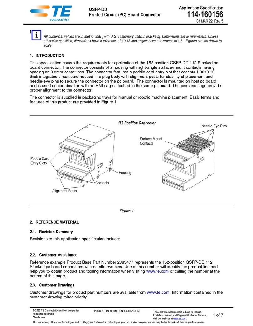
AMP-HDI pin and receptacle connectors are available
with two, three, or four rows of contacts, on a .100-in.
grid, totaling a maximum of 684 positions.
The connectors feature pin headers with ACTION
PIN* contacts; four-point, box-type receptacle
contacts; and a 64-combination keying arrangement.
One or two guide pins are used to facilitate reliable
mating of long connectors.
3. INSTALLING AMP-HDI CONNECTORS
3.1. Pin Connectors
When installing a pin connector into a pc board,
use of an insertion fixture is recommended to
protect the posts of the ACTION PIN contacts and
to support the connector and pc board in the
machine base. The insertion fixture is designed by
the customer for the specific connector size.
The connectors can be inserted into the pc board by
using the insertion tool listed in Figure 2 and by using
a power unit which is required for larger connectors
and larger pc boards.
Proceed as follows:
1. Place the pc board on top of the insertion fixture.
2. Align pc board holes with insertion fixture holes,
and loosely press connector contact posts through
holes in pc board and insertion fixture.
3. Select the appropriate insertion tool, and position
the tool in the top of the connector. See Figure 2.
4. Adjust the power unit to correct shut-height.
Receptacle
Connector
Guide Pin
PinConnector
(4-Row)
CONNECTORS
TYPE PART NUMBER
4-Row Pin 532435, 532448, 532818, 532837, 532841, 532921, 532933, 533056, 533254, 533270, 533404
Receptacle 532434, 532840, 532903, 532920
3-Row Pin 532432, 532438, 532447, 532839, 532919, 533061, 533092, 533093, 533094, 533294, 533296
Receptacle 532431, 532838, 532918, 533268
2-Row Pin 532429, 532446, 533060, 533090, 533091
Receptacle 532428, 532825
NOTE
i
NOTE
i
408-9007
2of 4
Rev A
Figure 2
5. Center connector under power unit and cycle
machine to insert connector.
6. Remove connector from power unit.
The maximum allowable gap between seated
connector and pc board is 0.25 mm [.010 in.].
3.2. Receptacle Connectors (Figure 3)
Receptacle connectors are installed into pc boards
by using Alignment Tool 532925 which aids in the
insertion of the connector into the pc board. The
tool is available in three lengths which incorporate
75, 135, and 180 contact positions, and the tool
featuresacam-actuatedleverto “open”and“close”
the tool on the receptacle contacts.
Refer to Figure 3 and proceed as follows:
1. Determine number of contact positions in the
assembly being mounted. Make a layout on the pc
board, using the recommended dimensions
provided in Figure 7.
2. Select proper tool, and adjust cam lever to
vertical position to place tool in “open” position.
3. Place contacts in alignment holes of tool, and
adjust lever to horizontal position to “close” the
alignment tool on contacts.
4. Place receptacle contacts through pc board holes
to position connector on pc board.
Figure 3
5. Adjust lever of tool to “open” position and slide
alignment tool from between the connector and pc
board.
6. Fasten connector to the pc board with
appropriate hardware.
7. Solder contacts to pc board using a standard
soldering technique.
4. REPLACING DAMAGED CONTACT
The pin and contact replacement tool, shown in
Figure 4 is used to replace ACTION PIN contacts on
pc boards and panels.
Figure 4
CONNECTOR ROWS INSERTION TOOL NUMBER
2 58172-1 thru 59172-7
3 58172-8 thru 1-58172-9
4 2-58172-0 thru 3-58172-7
Insertion Tool
Connector
PC Board
NOTE
i
NOTE
i
REPLACEMENT
TOOL REPLACEMENT
TIP REMOVAL
TIP KITPART
NUMBER
380392-8 308554-1 265964-1 265871-7
Receptacle
Connector
PC Board
ToolSlidesInto
Connector
Alignment
Tool
CamLever
(Open)
Pin and Contact
Replacement Tool
ACTION PIN Contact
Replacement Tip ACTION PIN Contact
Removal Tip
408-9007
3of 4
Rev A
The tool features a spring-loaded, internally-threaded
tip. The removal and replacement tips are designed to
remove or replace contacts of specific types and sizes.
The replacement tool tip is threaded into the tip of the
standard tool and fits onto the appropriate contact to
be replaced.
Forproperremovalandreplacementofthecontact,
the specified tool tips must be used. Replacement
tips can be obtained through your local
TE Connectivity Representative.
4.1. Contact Removal (Figure 5)
1. Thread the contact removal tip into the tip of the
replacement tool.
2. Position contact removal tip over square post of
contact.
3. Holding replacement tool and pc board firmly,
push contact out of the pc board and housing.
If the pc board or panel hasbeen soldered, contact
removal requires use of a soldering iron along with
the replacement tool for Steps 2 and 3. Hold hot tip
of soldering iron against the pin to be removed,
NOT against the pc board or panel. After the
contact is removed, use a .038-in. drill bit to clean
and size the hole for contact replacement. Do NOT
re-use ACTION PIN contacts that have been
removed.
Figure 5
4.2. Replacing Pin Contacts (Figure 6)
1. Thread appropriate ACTION PIN contact
replacement tip into tip of replacement tool.
2. After removing damaged contact, insert
replacement contact.
3. Fit hole in replacement tip over contact, rotate
tool 90° to locate contact in position, and apply force
in direction of arrow. See Figure 6.
The shoulder of contact must align with slot of
replacement tip before applying force to
replacement contact.
4. After applying force on contact to fully seat the
contact, the contact shoulder should be flush with
housing.
5. Remove replacement tool from contact.
5. REVISION SUMMARY
•Updated document to corporate requirements
•Deleted obsolete tool in Figure 2
•Deleted text in Paragraph 3.1
•New logo
Figure 6
NOTE
i
NOTE
i
Housing
PC Board
Removal Tip
Push Damaged
Contact Until It
Snaps Free
Pinand Contact
Replacement
Tool
NOTE
i
Replacement
Tool
Replacement
Tip
Apply Force Until Tool
Bottoms on Connector
Housing (Contact is
Fully Inserted)
408-9007
4of 4
Rev A

Other TE Connectivity Cables And Connectors manuals

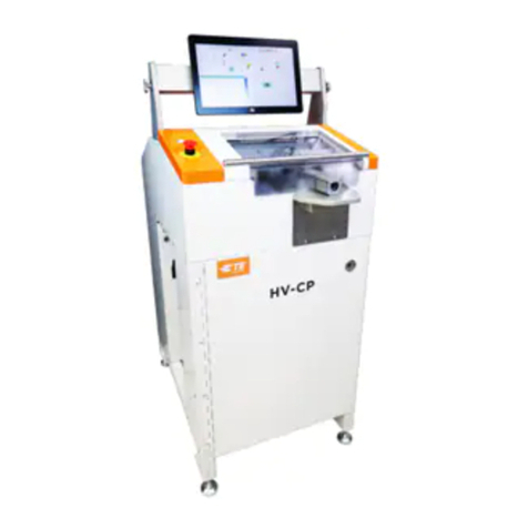
TE Connectivity HV-CP User manual

TE Connectivity

TE Connectivity HV-CP User manual

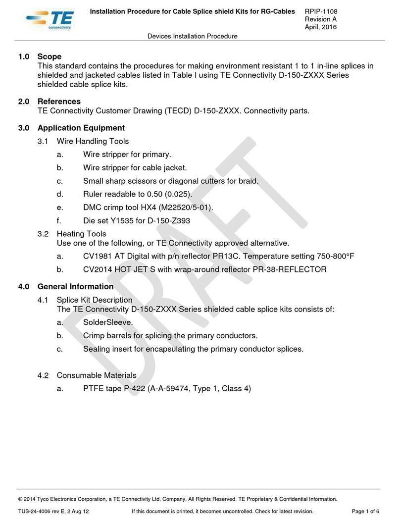
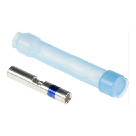
TE Connectivity SolderSleeve CWT Series Reference guide

TE Connectivity

TE Connectivity SolderSleeve CWT Series Reference guide

TE Connectivity HVA630-2phm User manual

TE Connectivity

TE Connectivity HVA630-2phm User manual

TE Connectivity Raychem LJSM Series User manual

TE Connectivity

TE Connectivity Raychem LJSM Series User manual

TE Connectivity DYNAMIC 5000 Series User manual

TE Connectivity

TE Connectivity DYNAMIC 5000 Series User manual

TE Connectivity TNC COAXICON Series User manual

TE Connectivity

TE Connectivity TNC COAXICON Series User manual

TE Connectivity 55PC1122-16-9/96-9 User manual

TE Connectivity

TE Connectivity 55PC1122-16-9/96-9 User manual

TE Connectivity AMPLIMITE HDP-20 User manual

TE Connectivity

TE Connectivity AMPLIMITE HDP-20 User manual

TE Connectivity MATE-N-LOK 2 794216-1 User manual

TE Connectivity

TE Connectivity MATE-N-LOK 2 794216-1 User manual

TE Connectivity RAYCHEM D-436 Series Reference guide

TE Connectivity

TE Connectivity RAYCHEM D-436 Series Reference guide

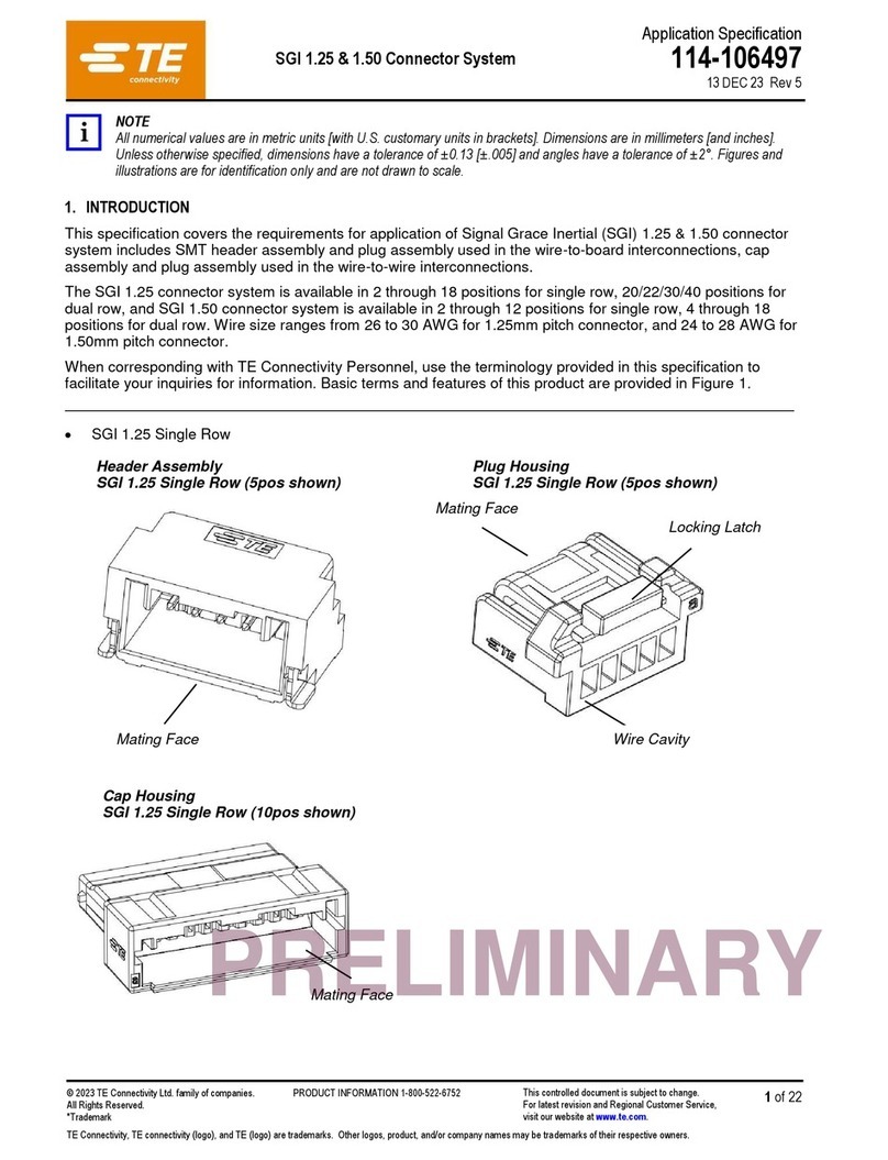
TE Connectivity SGI 1.25 User guide

TE Connectivity

TE Connectivity SGI 1.25 User guide

TE Connectivity RD-316 User manual

TE Connectivity

TE Connectivity RD-316 User manual

TE Connectivity EP-II User manual

TE Connectivity

TE Connectivity EP-II User manual

TE Connectivity AMPACT 83452 Series User manual

TE Connectivity

TE Connectivity AMPACT 83452 Series User manual

TE Connectivity M12 User guide

TE Connectivity

TE Connectivity M12 User guide

TE Connectivity RF COAXIAL User manual

TE Connectivity

TE Connectivity RF COAXIAL User manual

TE Connectivity GS-IPC-500U User manual

TE Connectivity

TE Connectivity GS-IPC-500U User manual

TE Connectivity VAL-U-LOK 3-1586040-6 User manual

TE Connectivity

TE Connectivity VAL-U-LOK 3-1586040-6 User manual

TE Connectivity QSFP-DD User guide

TE Connectivity

TE Connectivity QSFP-DD User guide

TE Connectivity AMPOWER 68361-1 User manual

TE Connectivity

TE Connectivity AMPOWER 68361-1 User manual

TE Connectivity HVA630-5p User manual

TE Connectivity

TE Connectivity HVA630-5p User manual

TE Connectivity AMP-LATCH User guide

TE Connectivity

TE Connectivity AMP-LATCH User guide

TE Connectivity Miniature AMP-IN User guide

TE Connectivity

TE Connectivity Miniature AMP-IN User guide

TE Connectivity D369 Series User manual

TE Connectivity

TE Connectivity D369 Series User manual

Popular Cables And Connectors manuals by other brands

Haufftechnik Systemdeckel HSI150 D Series installation instructions

Haufftechnik

Haufftechnik Systemdeckel HSI150 D Series installation instructions

A-Neuvideo ANI-HDAINSERT4K3 instruction manual

A-Neuvideo

A-Neuvideo ANI-HDAINSERT4K3 instruction manual

Tripp Lite P040-010 Specification sheet

Tripp Lite

Tripp Lite P040-010 Specification sheet

Philips SWV7255W Specifications

Philips

Philips SWV7255W Specifications

Clearfield FieldShield FLATdrop installation manual

Clearfield

Clearfield FieldShield FLATdrop installation manual

Pfisterer CONNEX Instructions for use

Pfisterer

Pfisterer CONNEX Instructions for use

LAPP EPIC H-Q 12 SCM Assembly instruction

LAPP

LAPP EPIC H-Q 12 SCM Assembly instruction

Philips DLC2401 brochure

Philips

Philips DLC2401 brochure

Panduit VeriSafe VSC Series installation instructions

Panduit

Panduit VeriSafe VSC Series installation instructions

Tyco Electronics AMP NETCONNECT AMPTRAC instructions

Tyco Electronics

Tyco Electronics AMP NETCONNECT AMPTRAC instructions

Philips Sonicare 300 SerieS Information

Philips

Philips Sonicare 300 SerieS Information

Lindy MST Hub 38402 user manual

Lindy

Lindy MST Hub 38402 user manual

Philips SWA3172S/10 Information

Philips

Philips SWA3172S/10 Information

Philips SWA2569 Specifications

Philips

Philips SWA2569 Specifications

AAxeon RS232 to USB Serial Adapter Cable installation guide

AAxeon

AAxeon RS232 to USB Serial Adapter Cable installation guide

KanexPro SP-HD1X24K manual

KanexPro

KanexPro SP-HD1X24K manual

Rockwell Automation Allen-Bradley Kinetix 2090 Series installation instructions

Rockwell Automation

Rockwell Automation Allen-Bradley Kinetix 2090 Series installation instructions

Lindy 38239 user manual

Lindy

Lindy 38239 user manual

manuals.online logo
manuals.online logoBrands
  • About & Mission
  • Contact us
  • Privacy Policy
  • Terms and Conditions

Copyright 2025 Manuals.Online. All Rights Reserved.