manuals.online logo
Brands
  1. Home
  2. •
  3. Brands
  4. •
  5. TE Connectivity
  6. •
  7. Cables And Connectors
  8. •
  9. TE Connectivity MATE-N-LOK 2 794216-1 User manual

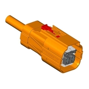
TE Connectivity MATE-N-LOK 2 794216-1 User manual

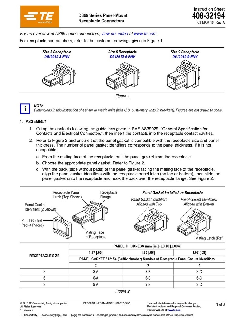
Vertical Pin Header
Right-Angle Pin Header Plug Housing
Cap Housing
Latching
Arm
Latching
Ear
Locking
Latch
PrintedCircuit(PC)
Board (Ref) Locking
Tab
Wires
(Ref)
Wires
(Ref)
WIRE CONTACT
SIZE RANGE
(AWG) INSULATIONDIAMETER
RANGE (mm [in.]) PIN SOCKET
STRIP LOOSE PIECE STRIP LOOSE PIECE
30-26 1.52 [.060] (Max) 794216-1 794224-1 794217-1 794225-1
794216-3 794224-3 794217-3 794225-3
26-22 1.19-1.75 [.047-.069] 794218-1 794226-1 794219-1 794227-1
794218-3 794226-3 794219-3 794227-3
22-18 or (2) 22 1.50-2.79 [.059-.110] 794220-1 794228-1 794221-1 794229-1
794220-3 794228-3 794221-3 794229-3
20-16 2.01-3.20 [.079-.126] 794222-1 794230-1 794223-1 794231-1
794222-3 794230-3 794221-3 794231-3
©2012 Tyco Electronics Corporation, a TE Connectivity Ltd. company
All Rights Reserved
*Trademark
TE Connectivity, TE connectivity (logo), and TE (logo) are trademarks. Other logos, product and/or company names may be trademarks of their respective owners.
1of 3
Instruction Sheet
TOOLING ASSISTANCE CENTER
1-800-722-1111

PRODUCT INFORMATION
1-800-522-6752
This controlled document is subject to change.
For latest revision and Regional Customer Service,
visit our website at www.te.com
408-3393

Mini-Universal MATE-N-LOK* 2
Connectors 20 JUN 12 Rev B
Figure 1
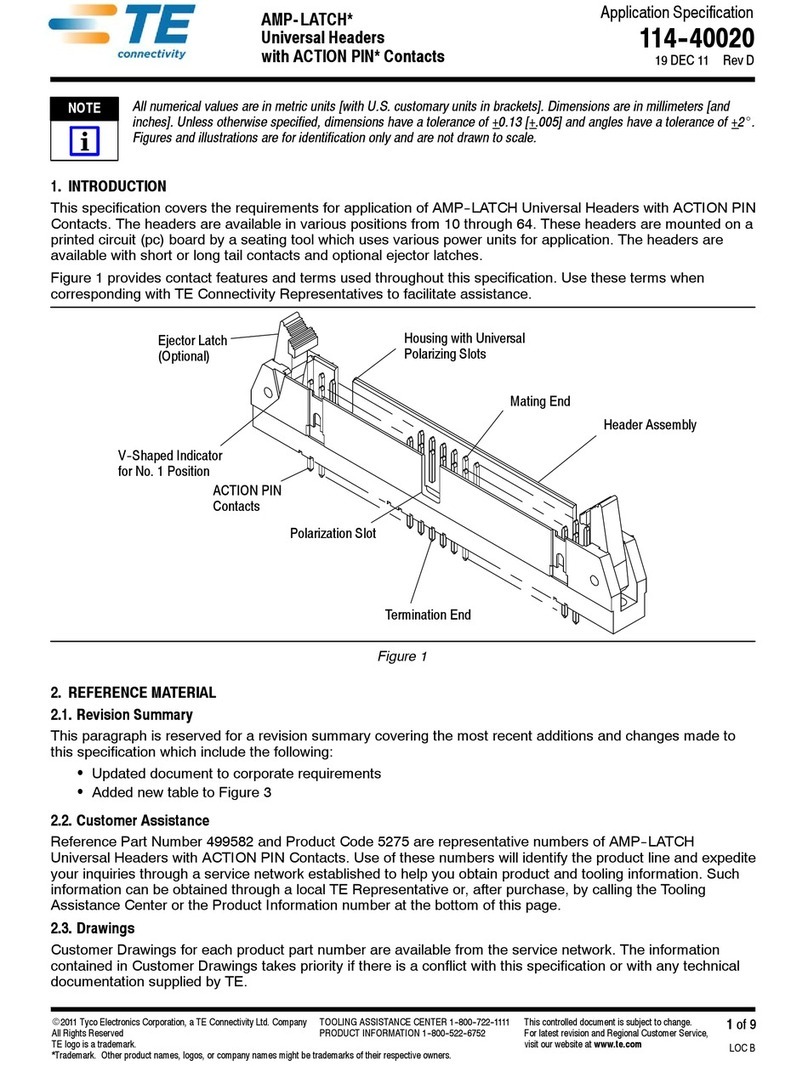
1. INTRODUCTION
This instruction sheet provides assembly and
disassembly procedures for Mini-Universal 
MATE-N-LOK 2 connectors used in free hanging or 
pc board applications.
Dimensions in this instruction sheet are in metric
units [with U.S. customary units in brackets].
Figures are not drawn to scale.
NOTE
i
Reasons for reissue of this instruction sheet are
provided in Section 6, REVISION SUMMARY.
2. DESCRIPTION (See Figure 1)
The pin header is available in vertical and right-angle
configurations. The plug housing and cap housing
accept the contacts listed in Figure 1. The housings
are polarized for proper alignment when mating. Keying
plugs are available to provide additional polarization
when mating the connectors. Positive locking features
prevent accidental disengagement of mated connectors.
3. ASSEMBLY PROCEDURE
3.1. Inserting Contacts
1. Select the appropriate pin and socket contacts
from Figure 1. Terminate the contacts according to
Application Specification 114-1111.
2. Rotate the wire end (back) of the housing 180
degrees along the pivot track until the first tooth of
each latching arm engages — the housing is in the
open position. See Figure 2.
!
CAUTION
408-3393
2of 3
Rev B
The wire end of the housing must be in the open
position before inserting the contacts.


Pivot
Track
First Tooth
Latching Arm
Wire End
of Housing
Housing in
Open Position
Latching Arm
Engaged
Figure 2
NOTE
i
3. From the wire end of the housing, align each
terminated pin or socket with the appropriate
contact cavity. Then grasp the wire directly behind
the contact insulation barrel and push the contact
with a twisting motion into the contact cavity until
the contact stops and the housing cone fingers
engage. See Figure 3, Detail A.
Terminated pin and socket contacts are
interchangeable between the housings. This or
keyingplugscanbeusedforadditionalpolarization
when mating the connectors.
Contact Contact
Cavity
Push
Housing Cone Fingers
(Not Engaged)
Housing Cone
Fingers Engaged
Contact
Insulation Barrel
Contact Insertion
Housing in
Closed Position
Second Tooth of
Latching Arm Engaged
4. After all required contacts and keying plugs have
been inserted into the housing, move the housing to
the close position. Grasp the wire end of the housing
and push it until the second tooth of each latching
arm engages as shown in Figure 3, Detail B.
3.2. Inserting Keying Plugs
1. Select an empty contact cavity of the housing to
be keyed. Ensure that the corresponding contact
cavity of the mating housing is empty. If it is not, the
keying plug will not engage.
2. With the housing in the open position (refer to
Figure 2), insert the keying plug into the wire end of
the housing. See Figure 4.
If removal of the keying plug is necessary, manually
or using pliers, grip the keying plug, and pull it from
the contact cavity using a twisting motion.
Figure 3
Keying Plug
Wires
Empty 
Contact Cavity
Housing in
Open Position
3. After all keying plugs have been inserted into the
housing, move the housing to the closed position.
Grasp the wire end of the housing and push it until
the second tooth of each latching arm engages
(refer to Figure 3).
Figure 4
3.3. Mating Connectors
1. Verify that the contact positions of the mating
connectors are identical.
2. Align and push the housing into the mating
connector until it bottoms and the locking latch
engages with the locking tab. See Figure 5.
Connector Mating
Locking Latch and
Locking Tab Engaged
Housings in Closed Position
Housing in
Closed Position
Locking Latch and
Locking Tab Engaged
408-3393
3of 3
Rev B
Figure 5
4. DISASSEMBLY PROCEDURE
4.1. Unmating Connectors
Depress the locking latch of the housing and pull the
housing straight away from the mating connector. See
Figure 6.
Depress Locking Latch Here
Pull Straight Away
Figure 6
!
CAUTION
4.2. Extracting Contacts
To prevent damage to the connector, the housing
must be in the open position before removing any
contacts.

!
CAUTION
1. Deflect the latching ears one at a time, then
lightly pull the wire end of the housing away from
the housing until the first tooth of the latching arms
engage. See Figure 7.
Take care not to over deflect the latching ears.



Contact Extraction
Housing in
Open Position
Contact
Insulation Barrel
Pull
Latching Ear
(Ref)
Disengaged Housing
Cone Fingers
Second Tooth of
Latching Arm Engaged
2. Grasp the contact insulation barrel and pull it
using a twisting motion until the contact is free from
housing. Refer to Figure 7.
Figure 7
5. REPLACEMENT AND REPAIR
The connectors and contacts are not repairable. 
DO NOT use defective or damaged product. DO NOT
re-use the contacts by removing the wire.
6. REVISION SUMMARY
Revisions to this instruction sheet include:
•Changed company name and logo
•Added Section 5

This manual suits for next models

59

Other TE Connectivity Cables And Connectors manuals
TE Connectivity TNC COAXICON Series User manual

TE Connectivity

TE Connectivity TNC COAXICON Series User manual

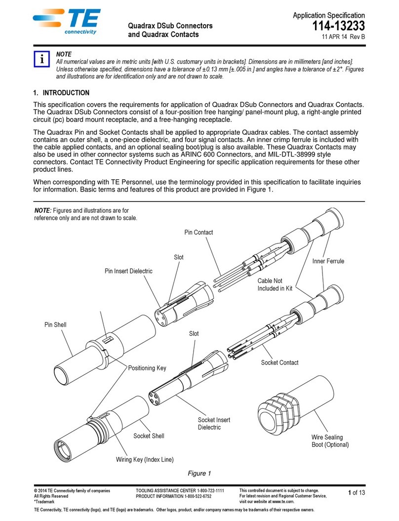
TE Connectivity Quadrax DSub User guide

TE Connectivity

TE Connectivity Quadrax DSub User guide

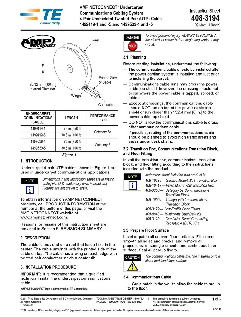
TE Connectivity AMP NETCONNECT 1499119-1 User manual

TE Connectivity

TE Connectivity AMP NETCONNECT 1499119-1 User manual

TE Connectivity M12 User guide

TE Connectivity

TE Connectivity M12 User guide

TE Connectivity D5000-S User manual

TE Connectivity

TE Connectivity D5000-S User manual

TE Connectivity AMP-LATCH User guide

TE Connectivity

TE Connectivity AMP-LATCH User guide

TE Connectivity AMPACT 83452 Series User manual

TE Connectivity

TE Connectivity AMPACT 83452 Series User manual

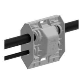
TE Connectivity HVP800 2PHI 90 User manual

TE Connectivity

TE Connectivity HVP800 2PHI 90 User manual

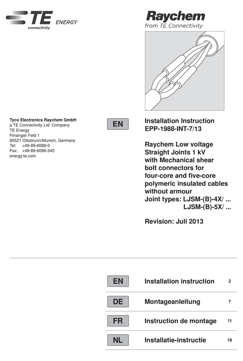
TE Connectivity Raychem LJSM Series User manual

TE Connectivity

TE Connectivity Raychem LJSM Series User manual

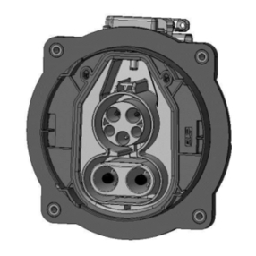
TE Connectivity CCS1 User manual

TE Connectivity

TE Connectivity CCS1 User manual

TE Connectivity AMPOWER 68361-1 User manual

TE Connectivity

TE Connectivity AMPOWER 68361-1 User manual

TE Connectivity DYNAMIC 5000 Series User manual

TE Connectivity

TE Connectivity DYNAMIC 5000 Series User manual

TE Connectivity DRC16 User manual

TE Connectivity

TE Connectivity DRC16 User manual

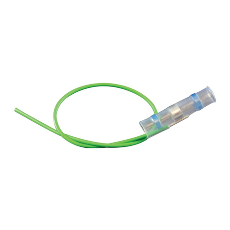
TE Connectivity SolderSleeve CWT Series Reference guide

TE Connectivity

TE Connectivity SolderSleeve CWT Series Reference guide

TE Connectivity QSFP-DD User guide

TE Connectivity

TE Connectivity QSFP-DD User guide

TE Connectivity D369 Series User manual

TE Connectivity

TE Connectivity D369 Series User manual

TE Connectivity HVA630-2phm User manual

TE Connectivity

TE Connectivity HVA630-2phm User manual

TE Connectivity GS-IPC-500U User manual

TE Connectivity

TE Connectivity GS-IPC-500U User manual

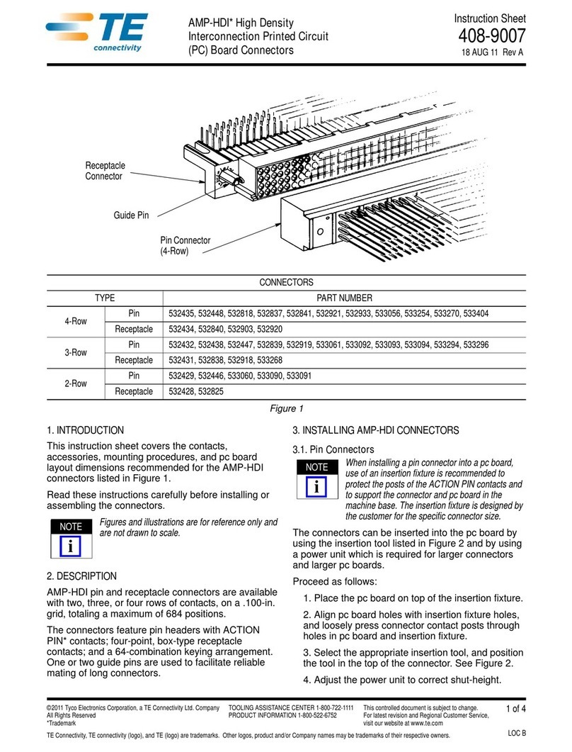
TE Connectivity AMP-HDI User manual

TE Connectivity

TE Connectivity AMP-HDI User manual

TE Connectivity AMPLIMITE HDP-20 User manual
TE Connectivity

TE Connectivity AMPLIMITE HDP-20 User manual

TE Connectivity EP-II User manual

TE Connectivity

TE Connectivity EP-II User manual

TE Connectivity RD-316 User manual

TE Connectivity

TE Connectivity RD-316 User manual

TE Connectivity Miniature AMP-IN User guide
TE Connectivity

TE Connectivity Miniature AMP-IN User guide

TE Connectivity 747564-9 User manual

TE Connectivity

TE Connectivity 747564-9 User manual

Popular Cables And Connectors manuals by other brands

ATEN VS0110HA user manual

ATEN

ATEN VS0110HA user manual

enphase IQ Series manual

enphase

enphase IQ Series manual

tellur green TLL155481 user guide

tellur green

tellur green TLL155481 user guide

Rocstor Y10C195-B2 user manual

Rocstor

Rocstor Y10C195-B2 user manual

MADRIX ORION user manual

MADRIX

MADRIX ORION user manual

Staubli MA213-05 Assembly instructions

Staubli

Staubli MA213-05 Assembly instructions

Fluke i5s instruction sheet

Fluke

Fluke i5s instruction sheet

ENSOTECH SWAVE-E2 user manual

ENSOTECH

ENSOTECH SWAVE-E2 user manual

Votronic 1430 Assembly and operating instructions

Votronic

Votronic 1430 Assembly and operating instructions

Eaton 600 A 35 kV Class Insulated Standoff Bushing Operation instructions

Eaton

Eaton 600 A 35 kV Class Insulated Standoff Bushing Operation instructions

OUNEVA Cu 35-150 2R manual

OUNEVA

OUNEVA Cu 35-150 2R manual

Holex 081193 15 instruction manual

Holex

Holex 081193 15 instruction manual

Digitus DS-45337 Quick installation guide

Digitus

Digitus DS-45337 Quick installation guide

GoMax Electronics SP-5028E user manual

GoMax Electronics

GoMax Electronics SP-5028E user manual

OUNEVA OT-PEN 95 Al/Cu installation guide

OUNEVA

OUNEVA OT-PEN 95 Al/Cu installation guide

Philips SDW5206GN Specifications

Philips

Philips SDW5206GN Specifications

ATLET 110781 Service manual

ATLET

ATLET 110781 Service manual

Philips SWV4133S/10 user manual

Philips

Philips SWV4133S/10 user manual

manuals.online logo
manuals.online logoBrands
  • About & Mission
  • Contact us
  • Privacy Policy
  • Terms and Conditions

Copyright 2025 Manuals.Online. All Rights Reserved.