Tele Radio Tiger D8-1 User manual

INSTALLATION INSTRUCTIONS
D8-1 ANALOGUE INPUT MODULE
Tele Radio Tiger
IM-TG-RX004-A03-EN
ARTICLE CODE: D8-1
LANGUAGE: ENGLISH (ORIGINAL)


Thank you for purchasing a Tele Radio product
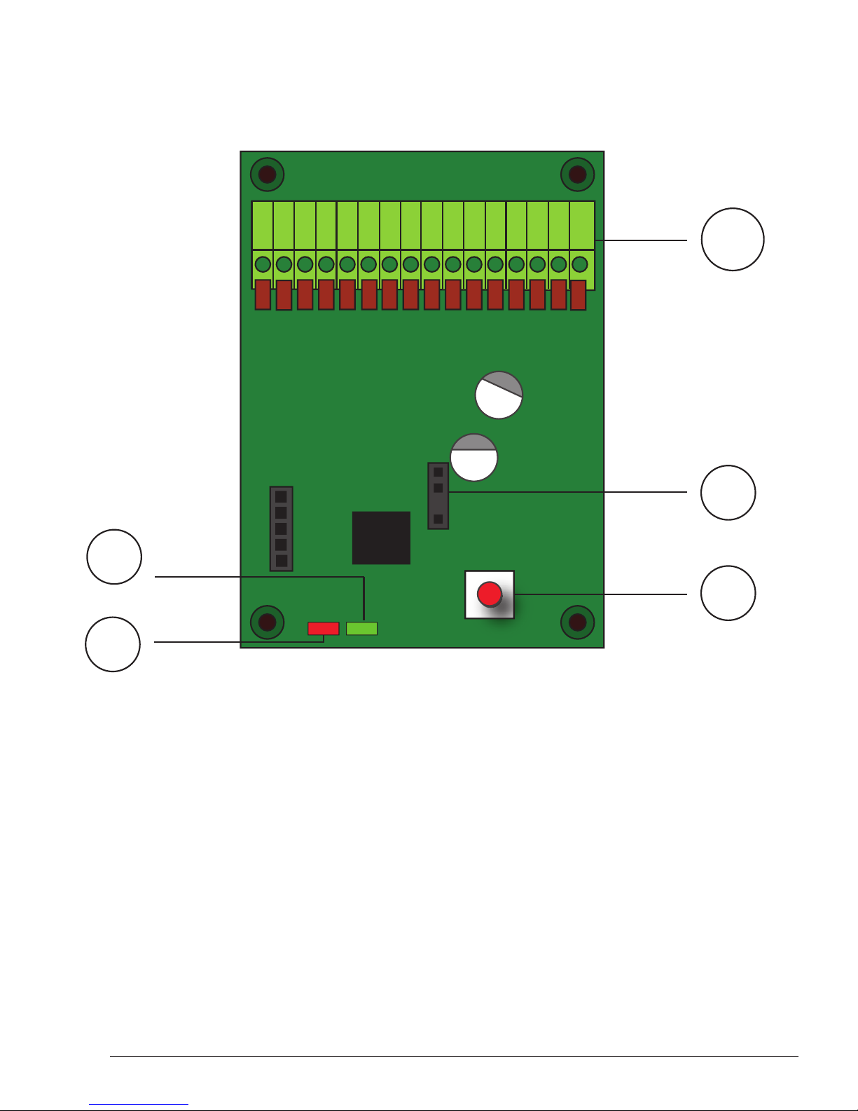
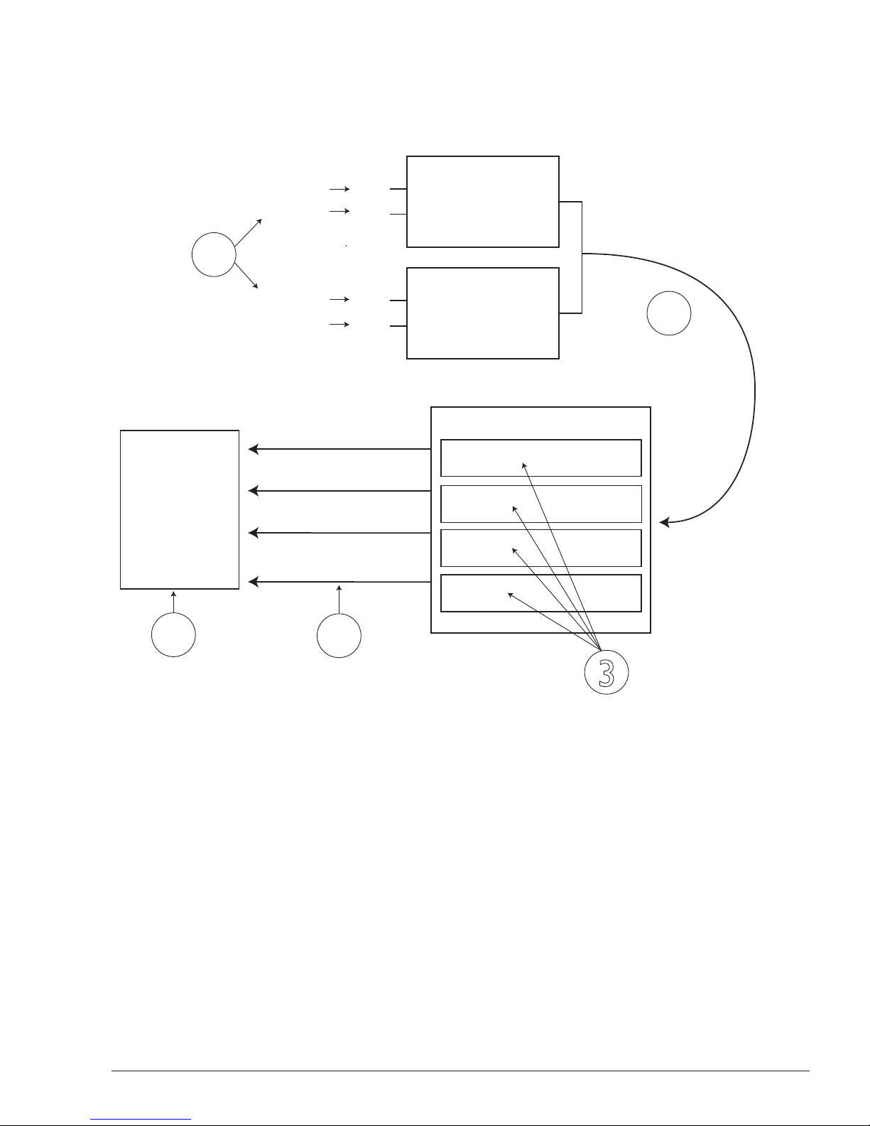
D8-1 analogue input module for Tiger receivers
READ ALL INSTRUCTIONS CAREFULLY BEFORE MOUNTING, INSTALLING AND
CONFIGURATING THE PRODUCT.
These instructions are published by Tele Radio AB without any guarantee.These
instructions are solely directed towards qualied installers. The instructions may be
removed or revised by Tele radio AB at any time and without any further notice.
Corrections and additions will be added to the updated versions of the instructions.
The instructions that contain information on the installation and conguration of the unit
on the machine are not intended to be passed on to the end user. Only such information
may be passed on to the end user, that is needed to operate the machine correctly by
radio remote control.
Tele Radio AB products are covered by a guarantee against material, construction or
manufacturing faults. During the guarantee period,Tele Radio AB may replace the product
or faulty parts with new. Work under guarantee must be carried out by Tele Radio AB
or by an authorized service centre specied by Tele Radio AB. Make sure that repairs and
maintenance are only carried out by qualied personnel. Use only spare parts from Tele
Radio AB. Contact your Tele Radio representative if you want to make a complaint about
a product or require other service.
The EC declaration of conformity can be downloaded from our website.
©Tele Radio AB, 2010
TELE RADIO AB
Datavägen 21, SE-436 32 Askim. Sweden
Tel: +46 (0)31-748 54 60
Fax: +46 (0)31-68 54 64
www.tele-radio.com.
info@tele-radio.com


5
Contents
CONTENTS
Technical data 7
FUNCTIONALITY 9
Clusters and signals 9
HOW TO CONNECT 11
Sensor connections 11
Modbus - Tiger connections 13
SETTINGS
Setup the Tiger receiver 14
Setup the Tiger transmitter 14
ALARM LIMIT SETTINGS ON THE RECEIVER
Overweight settings 15
Underweight settings 16
2-point calibration settings 18
System reset 18
Disposal of electronics 20

6Contents

7
Technical data
D8-1 overview
1. AIN1+
2. AIN1-
3. AIN2+
4. AIN2-
5. BRIDGE+
6. BRIDGE+
7. GND
8. GND
9. 5-24 V
10. 5-24 V
11. GND
12. GND
13. 485B
14. 485B
15. 485A
16. 485A
17. RS485-LED (red)
18. POWER-LED
(green)
19. SELECT BUTTON
20. PROGRAMMING
CONNECTOR
18 19
20
1-16
17
1 2 3 4 5 6 7 8 91011
1213141516

8
D8-1 data
Size: 80 x 54 x 38 mm./
3 x 2 x 1.5 in.
Weight: Max. 200 grams/ 7 oz.
Degree of protection: IP65
Operating temperature: -20 to 65°C/ -4 to 149 °F
Relative operating humidity: 10-90%
Relative storage humidity: <95%
Storage temperature: -30 to 70°C/ -22 to 158 °F
Enclosure material: Polycarbonate (PC)
Power supply: 5-24 V DC.
Current consumption: Approx. 100 mA.
SETUP (with a Tiger receiver):
No. of channels from each D8-1: 2 (0-10 V, 4-20 mA, 0-20 mA,
bridge)

9
1.The D8-1 unit can receive one signal (e.g. weight value) per channel.
Each D8-1 unit has 2 channels (CH 1 and CH2). Up to 16 D8-1 units
can be used with each receiver.A maximum of 16 weight values can be
handled.
When using one unit: One signal can be received on channel 1 and one
signal can be received on channel 2.
When using 2 units: One signal can be received on the rst unit´s channel
1 and one signal can be received on the rst unit´s channel 2. One signal
can be received on the second unit´s channel 1 and one signal can be
received on the second unit´s channel 2. I.e. 2 signals can be received
when using one D8-1 unit. 4 signals can be received when using 2 D8-1
units.
Functionality
Clusters and signals
CH1
CH2
CH1
CH2
D8-1
MODBUS slave
D8-1
MODBUS slave
RS485/MODBUS
TIGER RECEIVER
Cluster 1
Cluster 2
Cluster 3
Cluster 4
TIGER
TRANSMITTER
Alarm + warning
flags activates
feedback
1
2
4
3
5
Signals over
Signal out 1
Signal out 2
Signal out 3
Signal out 4
Signal in 4
Signal in 3
Signal in 1
Signal in 2
Input

10
2.The signals and alarm + warnings ags are distributed over RS485/
MODBUS to the Tiger receiver.
3. Each receiver have 4 clusters for handling the signals.We recommend
selecting an empty cluster for each new input signal. E.g. cluster 1 for the
1st input signal, cluster 2 for the 2nd input signal, cluster 3 for the 3rd
input signal and cluster 4 for the 4th input signal.
An upper alarm limit, an upper warning limit, an upper hysteresis limit
+ a lower alarm limit, a lower warning limit, a lower hysteresis limit can
be set for each cluster. One or more relays can be activated or blocked
when the alarm limits and warning limits are reached.The feedback can be
displayed according to your needs.
4.The weight value is the output from each cluster:Weight 1 is the output
from cluster 1, weight 2 is the output from cluster 2 etc. If more than one
weight value is received in a cluster, the output from that cluster is the
sum of the incoming weight values.
5.The transmitter will act upon the input from the receiver, e.g. show a
message in the display or ash a LED. NOTE! You will need a bindat le in
the transmitter to receive feedback.

11
SENSOR CONNECTIONS
Connect signal to D8-1- analogue input module
The green Power-LED ashes to indicate that the connection is correct.
Unbalanced connection
Connect a 0-20 mA, 4-20 mA or 0-10V sensor with 2 wires.
Terminal block Description Channel 1 Channel 2
AIN+ Analogue signal + 1 3
GND Analogue signal - 7 8
12345678
Channel 2
Channel 1
1
2
3
4
5
6
7
8
Channel
2
C
hannel 1
1 2 3 4 5 6 7 8 91011
1213141516

12
Balanced connection
Connect a 0-20 mA, 4-20 mA or 0-10V bridges sensor with 4 wires.
Terminal block Description Channel 1 Channel 2
AIN+ Analogue signal + 1 3
AIN- Analogue signal - 2 4
BRIDGE + Reference voltage to
bridge sensor 5 6
GND Ground 7 8
12345678
Channel 2
Channel 1
1 2 3 4 5 6 7 8 91011
1213141516

13
Example A shows how to connect a single D8 unit to a Tiger receiver. If 2
or more D8 units are being used, this is how the rst D8 unit should be
connected. See example B for how to connect multiple (2-16) D8 units to
the Tiger receiver via the rst D8 unit.
NOTE! Example B shows two D8 units.
MODBUS - TIGER CONNECTIONS
1 2 3 4 5 6 7 89101112
13141516 9 10 11 12 13 14
The Tiger receiver
D8 no. 1
9. RS232 Rx (not used)
10. RS232 Tx (not used)
11. Ground (black)
12. +12V DC (red)
13. RS485 A (blue)
14. RS485 B (green)
1 2 3 4 5 6 7 89101112
13141516
1 2 3 4 5 6 7 89101112
13141516
D8 no. 1
D8 no. 2
Example B
Example A

14
SETTINGS
Setup the D8-1- analogue input module
1. Connect the D8-1 unit to the PC program Settings Manager.
2. Go to MODBUS_ID and dene what Modbus slave address
that you want to assign your D8-1 unit, e.g.‘1’.
3. Go to CALIB_ID and dene what signal type that the D8-1
unit will receive, e.g.‘4-20 mA’.
4. Go to SIGNALTYPE and dene what signal type that the D8-1
unit will receive, e.g.‘Current’.
5. Save the new settings to the unit by clicking ‘Overwrite’.
6. Disconnect the D8-1 unit from the PC.
7. Turn the power off and then on to the D8-1 unit.
Setup the Tiger receiver
1. Connect the Tiger receiver to the PC program Settings
Manager.
2. Go to section 4 for cluster 1, section 5 for cluster 2, section 6
for cluster 3 or section 7 for cluster 4.
3. a. Go to MODBUSSENSORTYPE and select Sensor type
setting.
b. Select Input signal- Then select D8-1.
4. a. Go to MODBUSSLAVEADDRESS and select Slave address
setting.
b. Select Input signal.Then enter the slave address.
5. a. Go to SENSORCHANNEL and select Sensor channel
setting.
b. Select Input signal.Then select Sensor channel.
6. Disconnect the Tiger receiver from the PC.
7. Restart the Tiger receiver.The red RS485-LED (17) in the D8-1
unit ashes to indicate RS485 communication.

15
Setup the Tiger transmitter
1. Download a bindat le to make the transmitter ready to handle
feedback information.
Alarm limit settings on the receiver
NOTE! Use the same weight unit (e.g. ton) in all settings.
Overweight settings
Set the upper alarm limit
1. Connect the receiver to the PC program Settings Manager.
2. Go to section 4 for cluster 1, section 5 for cluster 2, section 6
for cluster 3 or section 7 for cluster 4.
3. Select MAXWEIGHTHIGH_LIMIT.
4. Dene the maximum weight, e.g. ‘1200’ for 1200 kg.
5. To block a relay(s) from activating when the weight equals
or exceeds the maximum weight limit (e.g. 1200 kg.), select
MAXWEIGHTHIGH_AND_RELAYS. Uncheck the relay(s)
that you want to block when the weight equals or exceeds the
maximum weight limit (e.g. 1200 kg.).
6. To activate a relay(s)/an indication relay(s) when the weight
equals or exceeds the maximum weight limit (e.g. 1200 kg.),
select MAXWEIGHTHIGH_OR_RELAYS. Check the relay(s)
that you want to activate when the maximum weight limit
(e.g. 1200 kg.) is reached.
7. To set a hysteresis value*, select WEIGHTHIGH_HYSTERESIS.
Dene the value: e.g. ‘200’.
Set an overweight warning limit
1. If you need an overweight warning, select
WARNINGWEIGHTHIGH_LIMIT.
2. Dene the overweight warning limit, e.g. ‘1000’ for 1000 kg.
3. To block a relay(s) from activating when the weight equals or
exceeds the overweight warning weight limit (1200 kg.), select
WARNINGWEIGHTHIGH_AND_RELAYS. Uncheck the

16
relay(s) that you want to block when the overweight
warning limit (e.g. 1000 kg.) is reached.
5. To activate a relay(s)/an indication relay(s) when the over
weight warning limit (e.g. 1000 kg.) is reached, select
WARNINGWEIGHTHIGH_OR_RELAYS. Check the relay(s)
that you want to activate when the overweight warning limit
(e.g. 1000 kg.) is reached.
Underweight settings
Set the lower alarm limit
1. Connect the receiver to the PC program Settings Manager.
2. Go to section 4 for cluster 1, section 5 for cluster 2, section 6
for cluster 3 or section 7 for cluster 4.
3. Select MINWEIGHTLOW_LIMIT.
4. Dene the minimum weight, e.g. ‘25’ for 25 kg.
5. To block a relay(s) from activating when the weight equals
or falls below the minimum weight limit (e.g. 25 kg.), select
MINWEIGHTLOW_AND_RELAYS. Uncheck the relay(s) that
you want to block when the minimum weight limit (e.g. 25 kg.)
is reached.
6. To activate a relay(s)/an indication relay(s) when the weight
equals or falls below the minimum weight limit, select
MINWEIGHTLOW_OR_RELAYS. Check the relay(s) that you
want to activate when the minimum weight limit (e.g. 25 kg.) is
reached.
7. To set a hysteresis value*, select WEIGHTLOW_HYSTERESIS.
Dene the value: e.g. ‘50’.
Set a underweight warning limit
1. If you need an underweight warning, select
WARNINGWEIGHTLOW_LIMIT.
2. Dene the underweight warning limit, e.g. ‘100’ for 100 kg.
3. To block a relay(s) from activating when the weight equals
or falls below the underweight warning weight limit (e.g.
100 kg), select WARNINGWEIGHTLOW_AND_RELAYS.

17
Uncheck the relay(s) that you want to block when the under
weight warning limit (e.g. 100 kg.) is reached.
4. To activate a relay(s)/an indication relay(s) when the weight
equals or falls below the WARNINGWEIGHTLOW_LIMIT
(e.g. 100 kg.), select WARNINGWEIGHTLOW_OR_RELAYS.
Check the relay(s) that you want to activate when the under
weight warning limit (e.g. 100 kg.) is reached.
*Hysteresis value
A hysteresis value can be used when there is a need for increasing the
tolerance for small deviations.An hysteresis value can be set for over-
weight and/or underweight, and applies for both the alarm limit + the
warning limit.
Example 1: Overweight settings
The WeightHigh_Limit is set to 2000 (kg.).A WeightHigh_Hysteresis value
is set to 500.When the incoming weight goes up to (or exceeds) the
WeightHigh_Limit, an alarm ag is raised.
Subtract the WeightHigh_Hysteresis value from the WeightHigh_Limit to
get the value where the ag will be lowered: 2.000-500= 1.500. The
incoming weight goes above 2.000 and the alarm ag for overweight is
raised.The incoming weight then drops to under 1.800, goes up to 1.900,
falls down to 1.800 before nally stopping at 1.880. Since the incoming
weight value never went below the WeightHigh_Hysteresis limit of 1.500,
the ag is still raised. If it had gone below, the alarm ag would have been
lowered.
In practice, raising the ag can be used for blocking or activating a relay
when the incoming weight value is too high. When the ag is lowered, the
same relay will block or activate again. If the incoming weight is uctu-
ating and you don´t use a hysteresis value, the relay will go on and off
every time the value passes the WeightHigh_Limit on its way up and
down.
An overweight alarm limit was set set to 1.700 (kg.). Subtract the
hysteresis value of 500 from 1.700.When the incoming weight goes up to

18
(or exceeds) the WarningWeightHigh_Limit, an alarm ag is raised. If the
incoming weight at any time goes below 1.200 (kg.), the alarm ag will be
lowered. Otherwise the alarm ag will stay raised.
Example 2: Underweight settings
The WeightLow_Limit is set to 25 (kg).A WeightLow_Hysteresis value
is set to 50.When the incoming weight goes down to (or fall below) the
WeightLow_Limit, an alarm ag is raised.
Add the WeightLow_Hysteresis value to the WeightLow_Limit to get the
value where the ag will be lowered: 50+25= 75. The incoming weight
goes down to 12 and the alarm ag for underweight is raised, up to 44,
down to 16, then up to 31 before nally stopping at 28. Since the incoming
weight value never went above the WeightLow_Hysteresis limit, the ag
is still raised. If the incoming weight value had gone above the hysteresis
limit, the alarm ag would have been lowered.
In practice, raising the ag can be used for blocking or activating a relay
when the incoming weight value is too low. When the ag is lowered, the
same relay will block or activate again. If the incoming weight is uctu-
ating and you don´t use a hysteresis value, the relay will go on and off
every time the value passes the WeightLow_Limit on its way up and down.
An underweight alarm limit was set to 100 (kg.).Add the hysteresis value
of 50 to 100.When the incoming weight goes under the WarningWeight-
Low_Limit, an alarm ag is raised. If the incoming weight goes above 150
(kg.), the alarm ag will be lowered. Otherwise the alarm ag will stay
raised.

19
2-point calibration settings
1. Select ‘1st point cal’ in the receiver menu.
2. Select the cluster to be calibrated, e.g.‘1’.
3. Connect a known load to the hook (we recommend no load
(zero weight), for the 1st point).
4. Enter the weight of the 1st known load in the receiver menu.
5. Select ‘2nd point cal’ in the receiver menu.
6. Select the same cluster, in this case ‘1’.
7. Connect a 2nd known load to the hook (we recommend 80-
100% of the maximum load. TIP! Pick calibration points that
differ as much as possible from one another for the best
result).
8. Enter the weight of the 2nd known load in the receiver menu.
System reset
Make a system reset to return to default values:
1. WITHIN 5 SECONDS FROM STARTING THE D8-1:
Press the D8-1 Select button.
The green Power-LED lights.
2. Keep the D8-1 Select button pressed for at least 5 seconds.
The green Power-LED goes out.

20
Disposal of electronics
Improperly disposed electronics may harm public health and the environ-
ment. Batteries and electronic waste may contain toxic heavy metals. If
thrown away in the trash, the toxic compounds can leach into soil and
water, pollute lakes and streams, making them unt for drinking, swimming,
shing, and wildlife. Contact your local government’s recycling or solid
waste department for more information on proper disposal of electronics
in your region.
RoHS and WEEE
In accordance with Directive 2002/95/EC on restriction
of the use of certain hazardous substances in electri-
cal and electronic equipment (RoHS) and Directive
2002/96/EC on waste electrical and electronic equip-
ment (WEEE),Tele Radio strives to minimize the use of
hazardous materials, promotes reuse and recycling, and
reduces emissions to air, soil and water.When a com-
mercially viable alternative is available,Tele Radio strives
to restrict or eliminate substances and materials that
pose an environmental, health or safety risk.
Table of contents
Other Tele Radio Remote Control manuals

Tele Radio
Tele Radio T60 User manual

Tele Radio
Tele Radio TG-T9-1 User manual

Tele Radio
Tele Radio PN-RX-MNB5 User manual

Tele Radio
Tele Radio Panther PN-R8-1 Installation instructions

Tele Radio
Tele Radio TG-TX-MNL6 Installation instructions

Tele Radio
Tele Radio T70 Jaguar User manual

Tele Radio
Tele Radio PN-RX-MNB4 User manual

Tele Radio
Tele Radio TIGER G2 User manual

Tele Radio
Tele Radio 860 Lion User manual

Tele Radio
Tele Radio Tiger T2 User manual