2022 © Copyright, Televés S.A.U.
Televes USA LLC. Norfolk Tech Center 16596 E. 2nd Avenue Aurora, CO 80011 televes.usa@televes.com www.televes.com
13
14
Screw connector Ponto the dipole assembly
Oand tighten with a 7/16th wrench but do not
overtighten, then slide the weather boot Qover
the connector as far as it will go.
Insert the dipole assembly Ointo the antenna
orange junction box, sliding it through the guide
slot to the point where you will hear an audible
“click” indicating the dipole is latched into place and
fully seated in the main body of the antenna.
Visually check the dipole once installed to make sure
there are no gaps and that it did fully seat
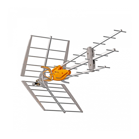
Ensure that the longest boom is assembled to be
the top of the antenna as shown in the diagram. The
tilt/elevation adjustment on the mounting clamps,
shown in the diagram, allows for adjustment of the
vertical angle of the antenna as needed for optimum
reception. Starting from a horizontal position, use
the mounting clamps to adjust tilt/elevation if
needed for better antenna adjustment and to aim
over nearby obstacles.
The long booms are the front of the antenna, as
shown in the diagram, and should be pointed
generally, in the direction of the TV transmitter
towers. Adjusting the antenna slightly either left or
right of the direction of the TV transmitter towers
may actually yield better performance as it may
reduce some unwanted interfering signals.
O
CLICK!
O
P
Q
12
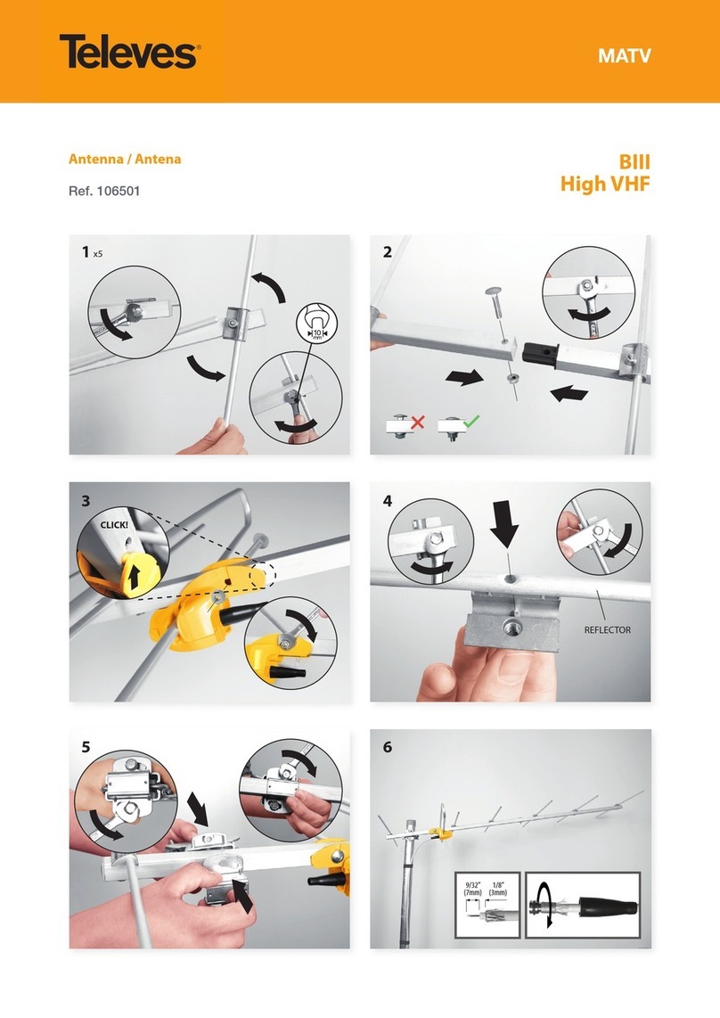
Release the shackles from the mast clamps Gby
removing and saving the shackle and nuts. Place the
antenna assembly on the mast (not included) and
proceed to replace the shackles and tighten the nuts
to attach the assembly to the mast.
The “elevation screws” will allow you to adjust the
antenna elevation (level, up or down to optimize the
installation). Be sure to tighten these screws once
the desired antenna position is obtained.
Elevation screws
FINAL NOTES:
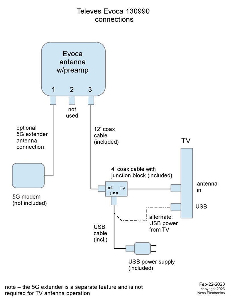
- Following the provided instructions, connect the
included power supply to the antenna using the
leftmost connector (closest to wall power) with an
appropriate length of 75 ohm coax, RG-6 or larger is
recommended. Make sure than any device installed
between the power supply and the antenna, such as
a splitter, is DC power passing. The two connectors on
the right of the power supply are for connecting your
TV’s and/or coaxial distribution.
- It may be necessary to alternate adjustments between
left and right and then tilt, several times in order to
achieve peak signal reception for the largest number
of desired channels.
- The antenna will work in an un-amplied, pass-through
mode, if the power supply is not connected or power
fails to reach the antenna for any reason. However, it is
recommended to always use the antenna with power
applied in order to activate the industry leading,
TForce automatic gain preamp that is built in to the
antenna.
- Always be sure to follow all local, state, and national
electric codes. Seek the assistance of a local
professional if needed.
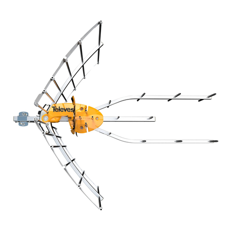
TOP of Antenna
The longest boom is the TOP
part of the antenna.
FRONT of Antenna
Aim this end TOWARDS
TV transmitting towers.
BACK of Antenna
Aim this end AWAY from
TV transmitting towers.
