TESTO 350 Maritime V2 How to use

testo 350 · Flue gas analyzer
Short manual

2

1 Contents
3
1Contents
1Contents ...................................................................................................3
1.1. Technical data .................................................................................4
1.1.1. Measurement ranges and resolution................................................................4
1.1.2. Other instrument data ......................................................................................5
2Product description.................................................................................6
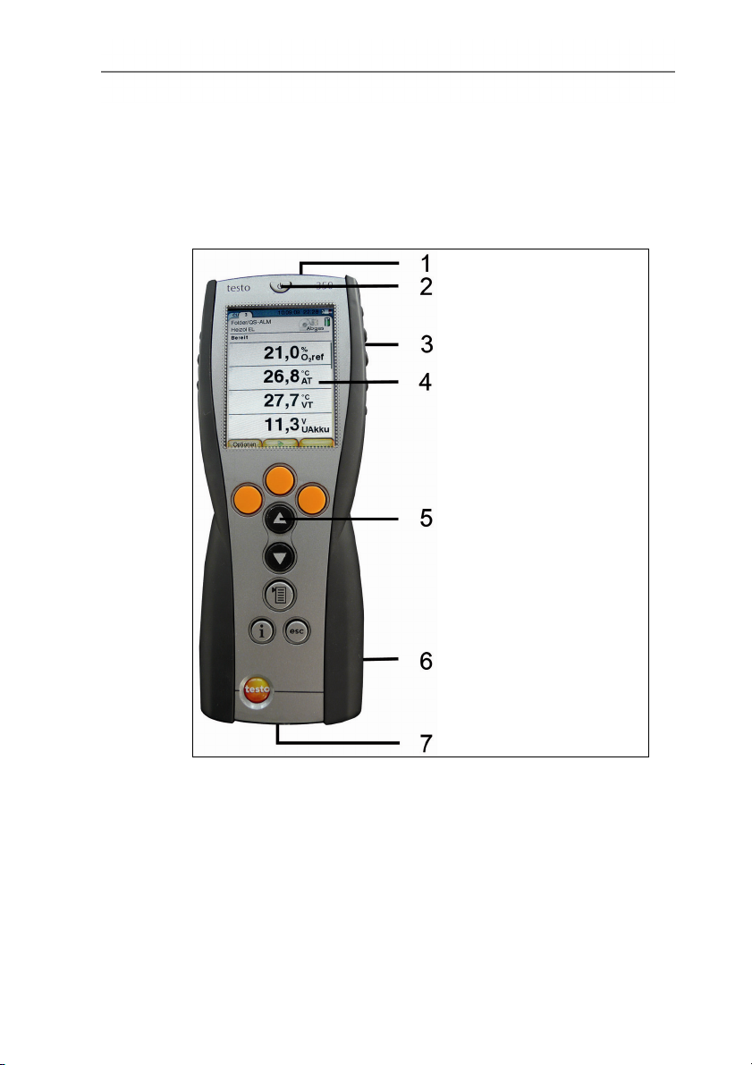
2.1. Control Unit......................................................................................6
2.1.1. Overview..........................................................................................................6
2.1.2. Keyboard .........................................................................................................7
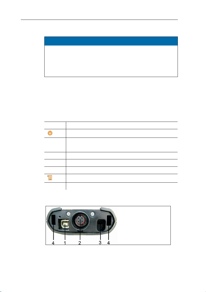
2.1.3. Connections / interfaces ..................................................................................7
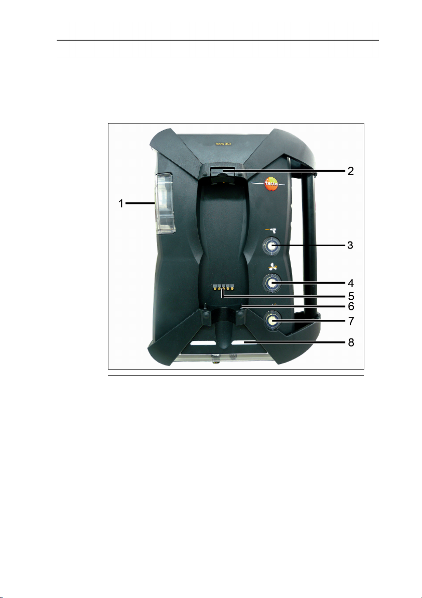
2.2. Meas. box........................................................................................8
2.2.1. Overview..........................................................................................................8
2.2.2. Status display ..................................................................................................9
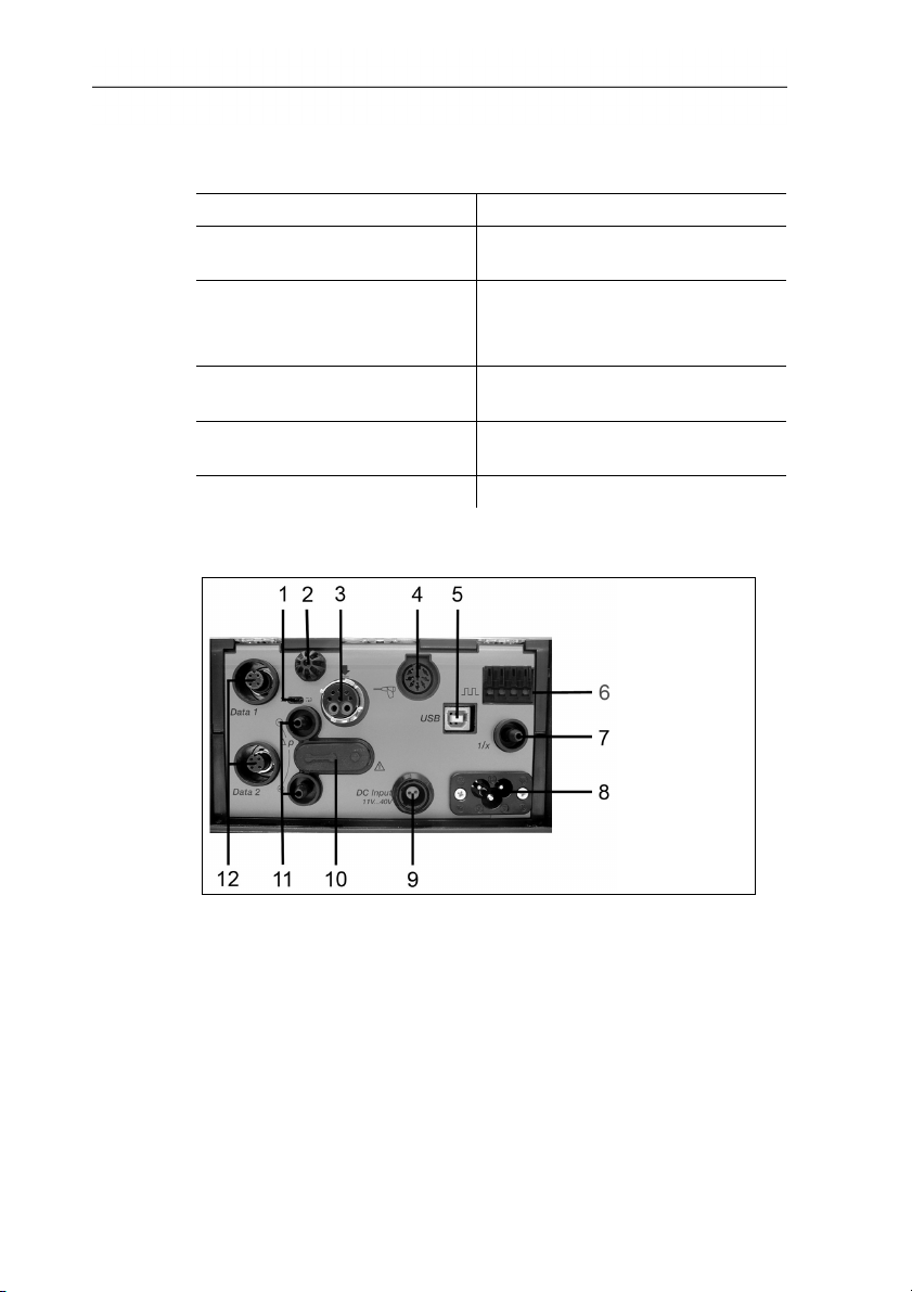
2.2.3. Connections / interfaces ..................................................................................9
2.2.4. Menu guidance meas. box............................................................................. 10
2.2.5. Modular flue gas probe ..................................................................................11
3First steps ..............................................................................................11
3.1. Commissioning ..............................................................................11
3.1.1. Control Unit.................................................................................................... 11
3.1.2. Meas. box ......................................................................................................12
3.2. Getting to know the product...........................................................13
3.2.1. Connecting probes / sensors .........................................................................13
3.2.2. Connecting system components ....................................................................13
3.2.2.1. Connection using contact strip.........................................................13
3.2.2.2. Connecting via Data bus cable (accessory).....................................13
3.2.2.3. Connection via Bluetooth®(option) ..................................................15
3.2.3. Switching on ..................................................................................................15
3.2.4. Printing / saving data .....................................................................................16
3.2.5. Switching off ..................................................................................................16
3.3. Folders / Locations ........................................................................17
4Using the product..................................................................................19
4.1. Performing settings........................................................................19
4.1.1. Assigning the right hand function key.............................................................19
4.1.2. Instrument settings ........................................................................................20
4.1.2.1. Measurement view ..........................................................................20
4.1.2.2. Date / time.......................................................................................22
4.1.3. Programs .......................................................................................................22
4.2. Measuring......................................................................................25
4.2.1. Preparing for measurement ...........................................................................25
4.2.2. Applications ...................................................................................................26

1 Contents
4
These brief instructions provide an overview over the most
important functions of the product. Before using the product
you should absolutely read and follow the operating
instructions!
This document describes the product testo 350 with the device
setting Country version | Great Britain.
1.1. Technical data
1.1.1. Measurement ranges and resolution
Analysis box
Measurement
parameter
Measurement
range without
dilution of all
sensors
Measurement range
with dilution of all
sensors (option)
O20…25Vol.%
The reading does not
appear in the display.
CO, H2-comp. 0…10000ppm 2500…50000ppm
COlow, H2-comp. 0…500ppm 500…2500ppm
NO 0…4000ppm 1500…20000ppm
NOlow 0…300ppm 300…1500ppm
NO20…500ppm 500…2500ppm
SO20…5000ppm 500…25000ppm
H2S 0…300ppm 200…1500ppm
CO2-(IR) 0…50Vol.%
The reading does not
appear in the display.
HC 1, 2Natural gas:
100…40000ppm
Propane:
100…21000ppm
Butane:
100…18000ppm
Natural gas:
500…8000000ppm
Propane:
500…42000000ppm
Butane:
500…36000000ppm
1Detection limit: 50ppm
2Strict compliance with the lower explosion limit is mandatory.

1 Contents
5
The dilution of all sensors results in an additional measuring error
(measuring inaccuracy).
1.1.2. Other instrument data
Control Unit
Feature Values
Rech. batt. service
life
approx. 5h (display switched on, Bluetooth®
deactivated)
Meas. box
Rech. batt. service
life
2.5h (with gas cooler and IR module) /
4.5h (without gas cooler and IR module)

2 Product description
6
2Product description
2.1. Control Unit
2.1.1. Overview
1IrDA interface
2Switch On / Off

2 Product description
7
3 Magnetic holder (on rear)
CAUTION
Strong magnets
Damage to other devices!
> Keep a safe distance from products which could be damaged
by magnets (e.g. monitors, computers, pacemakers, credit
cards).
4 Display
5Keyboard
6Contact bar for meas. box (on rear)
7 Interfaces: USB 2.0, charger, Testo Data bus
2.1.2. Keyboard
Key Functions
[] Switch measuring instrument on / off
[OK]
Example
Function key (orange, 3x), relevant function is shown on
the display
[▲]Scroll up, increase value
[▼]Scroll down, reduce value
[esc] Back, cancel function
[ ] Open main menu
[ i ] Open menu Instrument diagnosis
2.1.3. Connections / interfaces
1 USB 2.0
2Testo Data bus
3Connecting socket for mains unit 0554 1096

2 Product description
8
4Guide groove for locking with meas. box
2.2. Meas. box
2.2.1. Overview
1 Condensate trap and condensate container
2Locking/unlocking button for Control Unit
3 Particle filter
4 Filter fresh air inlet (option: fresh air valve / measurement range
extension overall (5x))
5 Contact bar for connection to Control Unit
6Guide pins for locking with Control Unit
7Diluting gas filter
8Status display

2 Product description
9
2.2.2. Status display
The status display shows the operating status of the meas. box:
Display Status
green / permanent (meas. box
switched on)
Mains operation or rech. batt
operation / rech. batt. fully charged
red / flashing (meas. box
switched on)
• Rech. batt. operation / residual
rech. batt. capacity < 20%
• other device error
green / flashing (meas. box
switched off)
Charge rech. batt.
green / permanent (meas. box
switched off)
Rech. batt. fully charged,
trickle charge
green, red / alternately flashing Update mode active
2.2.3. Connections / interfaces
1 Data bus termination slide switch
2Sensor for combustion air temperature
3 Flue gas probe
4 Sensor input
5 USB 2.0
6 Trigger input
7 Dilution gas inlet for measurement range extension
8 Mains connection 100...240V AC, 47...63Hz
9 DC-voltage input 11…40V DC (option)

2 Product description
10
10 Covering cap gas channel access (only for servicing purposes)
Plugged in covering cap: Position ( ) must
not be changed!
11Pressure ports p+ and p-
12Testo data bus
2.2.4. Menu guidance meas. box
Main menu Menu Description
Applications - Select an application in accordance
with the measuring task to be
performed
Folder - Create and manage folders and
locations
Fuels - Select and configure fuels
Measurement
Records
- Display and manage measurement
records
Device settings Dilution Set the dilution factor
Measurement view Configure the display, set
measurement parameters and units
for selected application and
measurement type
Units Set units for display variables
Date / time Set date, time, time format:
Power Options Set automatic instrument shut-down
and switch off display backlight in
rech. batt. operation
Display brightness Set display brightness
Printer Select printer, enter print text
Bluetooth®Bluetooth® on / off
Language Set instrument language
Country version Set country version (fuels, display
variables, calculation formulas)
Password protection Change password
Analog input Configure analog input
Databus Display of bus address, enter bus
length

3 First steps
11
Main menu Menu Description
Sensor settings - Make sensor settings, perform
calibration / adjustment
Programs - Configure and activate measuring
programs
Instrument
diagnosis
Error diagnosis Display of present errors
Gas path check Perform tightness test
Sensor diagnosis Perform sensor diagnosis
Device information Display of device information
2.2.5. Modular flue gas probe
1Removable filter chamber with window and particle filter
2 Probe handle
3 Connecting cable
4Connector plug for measuring instrument
5Probe module lock release
6Probe module
3First steps
3.1. Commissioning
3.1.1. Control Unit
The Control Unit has a permanently installed rechargeable battery.
> Remove the protective film from the display.
> Charge the rech. batt. fully before using the Control Unit.

3 First steps
12
Recharging the rech. batt. of the Control Unit
The rech. batt. can only be charged at an ambient temperature of
±0...+35°C. If the rech. batt. had been completely discharged, the
charging time at room temperature will take about 7h (charging with
mains adapter) or approx. 14h (charging via Testo Data bus).
Charging via meas. box
✓Control Unit is locked to meas. box or is connected via the
Testo Data bus cable.
✓ The meas. box is supplied via the mains unit.
During operation with low charge power or in switched off state.
3.1.2. Meas. box
The meas. box is supplied with a rech. batt. already fitted.
> Charge the rech. batt. fully before using the meas. box.
Charging the rech. batt. of the meas. box
The rech. batt. pack can only be charged at an ambient
temperature of ±0...+35°C. If the rech. batt. has been discharged
completely, the charging time at room temperature is approx. 6h.
✓ The meas. box is switched off.
> Connect mains cable to meas. box and mains socket.
- Charging will start, the fan may come on automatically. The
status LEDs lights green while the rech. batt. is being charged.
- Once the rech. batt. has been charged the instrument will
automatically change to trickle charge. The status LEDs
permanently light green.
Meas. box via DC-voltage input DC
Cable with battery terminals and adapter for connection to meas.
box required (0554 1337, accessory)
- If the meas. box is switched off the rech. batt. charging process
will start automatically. Battery charging stops when the flue gas
analyser is switched on by the Control Unit.

3 First steps
13
3.2. Getting to know the product
3.2.1. Connecting probes / sensors
Sensor detection takes place during the activation
process: Sensors that are required must always be
connected before the flue gas analyser is switched on,
or the flue gas analyser must be switched off and then
on again after a sensor change, so that the correct
sensor data can be read.
> Connect the required probes / sensors to the corresponding
ports.
3.2.2. Connecting system components
3.2.2.1. Connection using contact strip
The Control Unit can be plugged on and locked to the meas. box.
1.Place the guide groove in the bottom side of the Control Unit
over the guide pins of the meas. box.
2.Press the Control Unit against the meas. box until the locking/
unlocking buttons noticeably clicks into place two times.
To protect the display (e.g. during transport) the Control
Unit can also be inserted with the back facing up, however,
in this case there is no connection to the meas. box.
3.2.2.2. Connecting via Data bus cable (accessory)
The individual components (e.g. Control Unit with meas. box or
meas. box with meas. box) can be connected using the Testo
databus cable.
> Connect the Data bus cable to the Data bus interfaces.

3 First steps
14
Please observe the following points when setting up a connection
via databus cable:
• Use only Testo databus cables
• Do not route databus cables in the vicinity of electric power
cables.
• Ensure sufficient power supply by supplying each meas. box
with mains voltage.
• The cables should ideally be plugged in before the system is
switched on. Connecting during operation (hot plugging) is
possible, however, depending on the combination the system
may need to be switched off and on again.
• The connection cannot be separated under load.
• Data bus subscribers: max. 16 meas. boxes in one Data bus
system.
• Cable length: max. 50m between Control Unit and meas. box,
max. 800m between all meas. boxes in the databus system.
• Each component in the Data bus system must have an
unambiguous bus address.
• The bus system must have a defined electrical termination, see
below.
Electrical termination of the bus system
The databus system is linear in structure. The Control Unit or the
Testo databus controller with USB connection represents the
beginning of the line.
The end is represented by the last components connected in the
system (meas. box or analog output box). This component must
have a defined electrical termination.
An analog output box is the furthest subscriber.
> Insert the Data bus termination plug into the Data bus socket on
the analog output box.
A meas. box is the furthest subscriber.
> Set the Data bus termination slide switch in the meas. box to
switch position right ( ).

3 First steps
15
3.2.2.3. Connection via Bluetooth®(option)
or
or
The Control Unit can be connected to a meas. box or a PC/
Notebook via Bluetooth®, as long as both components are
equipped with this function.
3.2.3. Switching on
Before switching on
> Connect all system components.
> Connect all required probes / sensors.
> Connect all system components to the electric power supply.
When switching on the Control Unit
- should be plugged on the contact strip of the meas. box
or
- connected with a Data bus cable

3 First steps
16
or
- plugged to the mains cable of the meas. box, so that starting via
Bluetooth®is enabled.
Switching on
> press [].
- The Welcome Screen is displayed (approx. 5s)
- The Control Unit display screen appears.
- The Control Unit searches for connected meas. boxes and
shows these as independent tabs in the display.
Control Unit and meas. box are not connected:
If the Control Unit has already been switched on, you must
press []once again for a short moment to set up a
connection to the meas. box.
3.2.4. Printing / saving data
Printing and saving is accomplished via the menu Options, which
is accessed via the left function key and is available in many
different menus (e.g. in the menu Measurement Type).
Assign the function Save or Print to the right function key.
Only readings, which have a display field in the
measurement view assigned, will be saved / printed out.
The measurement data can be printed out parallel to the
saving process, while a measurement program is running.
3.2.5. Switching off
Unsaved readings will be lost when the flue gas analyser is
switched off.
Rinse phase
When switched off, the meas. box checks whether flue gases are
still in the sensors. The sensors are rinsed with fresh air, if this
should be necessary. The duration of the rinse phase depends on
the gas concentration in the sensors.
> press [].
- The rinse phase starts.
- The flue gas analyser switches off. It is normal for the fan of the
meas. box to run on for a while.

3 First steps
17
3.3. Folders / Locations
(only available via Meas. Box tab)
All readings can be saved under the currently active location.
Readings not yet saved are lost when the measuring instrument is
switched off.
Folders and locations can be created, edited, copied and activated.
Folders and locations (incl. protocols) can be deleted.
Calling up the function:
> [] →Folders →[OK].
Adapting the display:
> Toggle between overview (display of number of locations per
folder) and detailed view (display of all locations per folder):
[Overview] or [Details].
Activating a location:
> Select the location →[OK].
- The location is activated and the menu Measurement Type is
opened.
Creating a new location:
A location is always created in a folder.
1.Select the folder in which the location is to be created.
2.[Options] →New location→[OK].
3.Enter values or make settings.
The following inputs/settings are possible:
Parameter Description
Location Enter name
Application Select application
Fuel Select fuel
Profile Enter diameter, length, width, height and area.
For correct measurement of the volume flow you
must set the profile and area. A volumetric flow rate
is calculated from the geometries entered here
together with the measured velocity.

3 First steps
18
Parameter Description
Pitot Tube
Factor
The parameter "Pitot tube factor" influences the
measurement of flow speed, volume flow rate and
mass flow. The Pitot factor depends on the type of
Pitot tube used:
Straight Pitot tubes: Factor = 0.67
Prandt’l Pitor tubes (bent): Factor = 1
Humidity The parameter "Humidity" (combustion air humidity)
influences the calculation of qA (flue gas loss) and
flue gas dew point. The factory setting is 80.0%
humidity. To achieve a higher accuracy, the values
can be adjusted to the actual ambient conditions.
Pressure
absolute
The absolute pressure influences the calculation of
flow speed, volume flow, mass flow and flue gas
dew point. The factory setting is 980mbar. To
achieve a higher accuracy, the values can be
adjusted to the actual ambient conditions.
If a CO2-(IR) module is installed, the
absolute pressure value measured there will
automatically be used.
Barometric
pressure
The input of the barometric pressure and the
height above sea level is only required when
no absolute pressure is available (no CO2IR
module present).
The barometric pressure influences the calculation
of flow speed, volume flow, mass flow and flue gas
dew point. To achieve a higher accuracy, the values
can be adjusted to the actual ambient conditions.
This is 1013mbar as an annual average, regardless
of the altitude. Depending on the current weather,
this pressure can fluctuate by ±20mbar around the
annual average.
Altitude The height above sea level influences the
calculation of flow speed, volume flow, mass flow
and flue gas dew point. To achieve a higher
accuracy, the value can be adjusted to the actual
ambient conditions.

4 Using the product
19
Parameter Description
Dewpoint The parameter "Dewpoint" (combustion air
dewpoint) influences the calculation of qA (flue gas
loss) and flue gas dew point. The factory setting for
the dewpoint is 1.5°C. To achieve a higher
accuracy, the values can be adjusted to the actual
ambient conditions.
4.Finalise the entry: [Finished].
Other location options:
> [Options] →Edit location: Make changes to an existing
location.
> [Options] →Copy location: Make a copy of an existing
location in the same folder.
> [Options] →Delete location: Delete an existing location.
Create a new folder:
1.[Options] →New Folder →[OK].
2.Enter values or make settings.
3.Finalise the entry: [Finished].
Other folder options:
• Edit Folder: Make changes to an existing folder.
• Copy Folder: Make a copy of an existing folder.
• Delete Folder: Delete an existing folder, including the locations
created therein.
• Delete All Folders: Delete all existing folders, including the
locations created therein.
4Using the product
4.1. Performing settings
4.1.1. Assigning the right hand function key
The right function key can have a function from the Options menu
assigned to it. The menu Options is accessed via the left function
key and is available in many different menus. This assignment is
only valid for the currently opened menu / the opened function.

4 Using the product
20
✓ A menu / function is opened in which the Options menu is
displayed on the left function key.
1.Press [Options].
2.Select option: [], [ ].
Depending on the menu / function from which the Options menu
was opened, various functions are available.
3.Assign the selected function to the right function key: Press the
[Config. Key].
4.1.2. Instrument settings
4.1.2.1. Measurement view
(only available via Meas. Box tab)
The parameters / units and the display representation (number of
readings displayed per display page) can be set.
The settings are only valid for the currently chosen combination of
application and measurement type, which is indicated by the
symbol (application) and the text (measurement type) in the info
field.
Total overview of selectable parameters and units (available
selection depends on the chosen application / measurement type):
Display Measurement parameter
FT Flue gas temperature
AT Combustion air temperature
HCT Heat carrier temperature
Δp Differential pressure
Δp1 Differential pressure 1 (flue gas + m/s)
Δp2 Differential pressure 2 (flue gas + ΔP)
Draught Flue draught
Pabs Absolute pressure
Pump Pumping capacity
O2 Oxygen
O2ref Oxygen reference
CO2 Carbon dioxide
CO2max maximal carbon dioxide content
Effn Efficiency
Other manuals for 350 Maritime V2
4
Table of contents
Other TESTO Measuring Instrument manuals
Popular Measuring Instrument manuals by other brands

Rohde & Schwarz
Rohde & Schwarz ZNB Getting started

Barbieri
Barbieri Spectropad Series 2 operating manual

LaMotte
LaMotte 1200 instruction manual

Parker Pneumatic
Parker Pneumatic MPS-4 Series Installation & service instructions

Vector
Vector 5200-00 user guide

Fluke
Fluke Nuclear Associates 07-453 Operator's manual