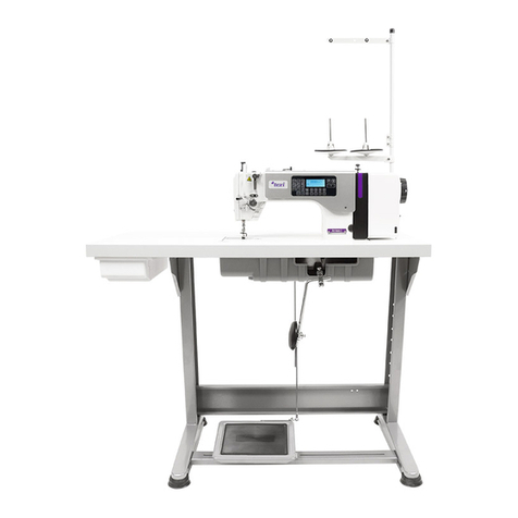
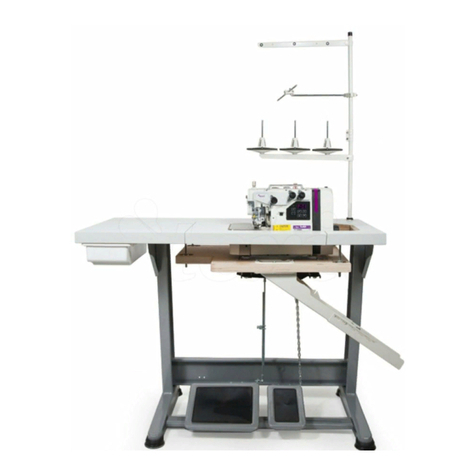
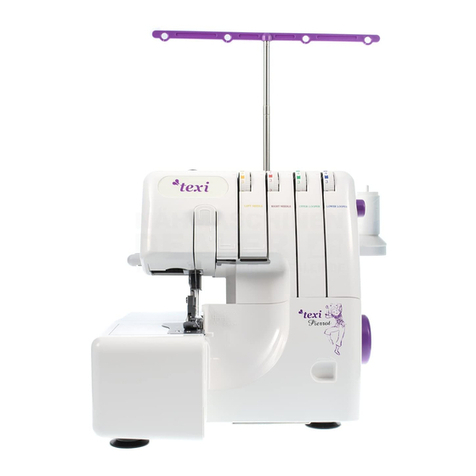
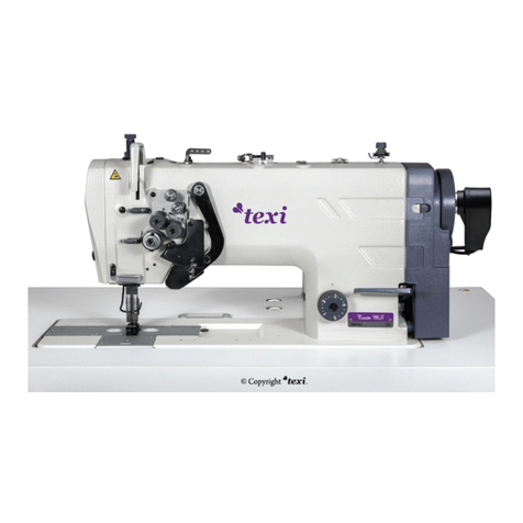
Texi Tronic 5 User manual

Operation manual
for high speed direct drive automatic lockstitch
machine
with built-in energy saving motor
Tronic 5


1
TEXI Tronic 5 operation manual
Contents
Safety precautions
User’s manual for the automatic lockstitch machine
1. Before starting work
2. Installation
3. Lubrication
4. Correct oil dosage to the hook
5. Fastening the needle
6. Insertion of bobbin into bobbin case
7. Threading the machine
8. Winding the bobbin
9. Stitch length regulation
10. Installing the thread stand
11. Replacing counter knife and moving knife
12. Thread cutting regulation
13. Lifting presser foot by means of the knee lifter
14. Pedal operation
15. Thread tensioner
16. Compensating spring regulation
17. Manual foot lifter
18. Foot pressure regulation
19. Feed timing adjustment
20. Feed dog tilting
21. Feed dog height regulation
22. Needle bar and hook regulation
23. Setting foot bar stroke
24. Setting thread guide
25. Adjusting of needle stop position
26. Changing pedal pressing force
27. Pedal regulation
28. Automatic reverse feed stitching mechanism
Ask your supplier about:
CE Declaration of conformity

2
IMPORTANT!
This instruction manual contains important guidelines regarding correct, safe and economical method of use of the machine.
Following recommendations contained in this manual will decrease work down-time, increase machine reliability and durability,
and will make work safer.
This instruction manual must always be available at the workplace. The machine can be serviced only by an employee trained
in Industrial Safety, after reading this instruction manual.
The supplier is not responsible for damages caused by improper use or by usage of this product for functions other than those
it has been designed for.
GENERAL SAFETY PRECAUTIONS
To minimize the risk of fire, electric shock, or injury, observe the following precautions:
- Keep the workplace clean.
- Pay attention to the machine’s work environment; do not subject it to atmospheric conditions.
- Do not install the machine in rooms that are dusty, where aerosols are sprayed, or to which oxygen is supplied.
- Keep the workplace well lit.
- Be careful of danger of electric shock.
- Pay attention to clothing. Let-down hair or loose clothing can be caught by the machine’s mobile elements.
- Take care not to damage the power supply cable.
- When the machine is not in use, disconnect it from the power grid.
- Take care not to turn-on the machine accidentally.
- In case of even the slightest damage, always check if the damaged part requires replacement.
- Never install on the machine attachments and accessories other than those recommended by the manufacturer and supplier.
- Do not perform machine modifications independently.
- Do not leave near the machine unattended bystanders or children.
Electric installation
Check if the supply voltage in the electric socket corresponds to the data on the machine’s rating plate 1-phase voltage 230V
50Hz.
Check the correctness of electric connections in the plug and electric socket, observing electric shock safety countermeas-
ures.
Do not use extension power cords.
Apply the valid electrical and Industrial Safety norms.
ATTENTION – all work related to the electrical installation must be carried out by a qualified electrician.
Before starting work
Using machine without any of the safeguarding parts (finger guard, eye guard, etc.) is dangerous to an operator.
During work, only the items necessary for sewing should be found on the machine’s work table.
Before connecting the machine to the power grid, always release the pedal and the start button.
Do not use blunt or bent needles.
Do not touch any of the machine’s mobile elements, such as the needle, needle bar, thread tensioner or take-up, or hook,
during its operation.
Turn machine off before: replacing needle, threading, installing attachments, changing the bobbin or bobbin case.
If you notice any abnormalities in the machine’s function, turn it off immediately and inform a mechanic or your superior. After
finishing work, turn the machine off and remove the plug from the electric socket. In case of power grid failure, disconnect the
machine from the power grid.
This machine is not a toy!
We hope that you will use this machine with pleasure for a long time.
TEXI Tronic 5 operation manual
3
USER’S MANUAL
The lockstitch machine TEXI, Tronic 5, is a high speed sewing machine, designed for sewing woven or knitted mate-
rials or other textiles.
Attention!
The machine is not to be used for other materials than those for which it has been designed.
Non-observance of this rule places the user at risk and can cause irreversible damage to the machine.
Before use, the user should become acquainted with this instruction manual, general safety precautions and mainte-
nance instructions.
1. Before starting work
1. After turning-on the machine and during its operation, do not touch the needle or put fingers into the
thread cutter guard.
2. During sewing, do not put fingers into the needle guard.
3. Before tilting the machine head or uninstalling guards, turn power off.
4. Turn machine off before leaving it unattended.
5. Do not allow hair, loose clothing, fingers or any objects to be in the vicinity of the pulley during machine
run.
6. Do not clean the machine with paint thinner.
Technical specifications
TEXI Tronic 5 operation manual

4
TEXI Tronic 5 operation manual
2. Installation
Installation of the oil reservoir:
The oil reservoir should rest upon four corners of the cut-out in the machine table-top (Fig. 1).
- Fasten the two-armed washer [1] on side A of the oil reservoir [3], in the direction of the operator, Fig. 2.)
- Fasten the two washers [2] on side B of the oil reservoir [3], (from the side of the hinges), then fasten the oil res-
ervoir [3] (Fig. 1, Fig. 2).
Machine head installation
- Insert hinge [1] into the opening in the machine head, place machine head on table-top with the hinge in the re-
cess and fasten it on the washers in the four corners of the reservoir (Fig. 3, Fig. 4).
Attention: In the packaging, the four rubber washers placed in the corners of the oil reservoir, are for transportation
purpose only.
3. Lubrication
1. Fill the oil reservoir [1] with high-speed machine oil,
up to the level of upper marker A.
2. When the oil level falls to the level of lower marker
B, refill the reservoir.
3. During machine operation, oil spatter will be visible
in the eye-hole. Remember that the amount of oil
spatter is not related to the amount of oil in the oil
reservoir.
*Attention: during first machine start-up, or after a long
idle time, it should be started at a speed of 2000/min
to 2500/min for about 10 minutes, in order to grind in
co-acting parts.

5
TEXI Tronic 5 operation manual
4. Correct oil dosage to the hook
1. Before starting regulation:
1) First, for testing, the new machine should operate for about 3 minutes without material.
2) Checking oil using the paper oil level indicator should be carried out during the machine’s operation.
Make sure that the oil level in the oil pan is between the upper and lower marker.
3) The time for checking oil level should be 5 seconds.
2. Oil level
An insufficient amount of oil can cause hook overheat or seizing; too much oil can cause staining of the sewed
material.
3. Regulation of oil dosage to the hook:
Attention: Check oil amount three times and set oil amount so that the mark on the paper oil level indicator is the
same every time.
1) After turning the screw located on the front sleeve of the lower shaft in direction A, the oil dosage will increase;
in direction B - it will decrease.
2) After carrying out regulation, activate the machine for 30 seconds without material to check if the amount of oil
is correct.

6
TEXI Tronic 5 operation manual
5. Fastening the needle
Before fastening the needle, turn power off.
1. Select needle size and tip appropriate to the stitch
and material type.
2. Turn the pulley until the needle bar is found in its
highest point.
3. Loosen screw [2] and hold the needle with part A
directed to direction B.
4. Insert needle in the direction indicated by the ar-
row, until stops.
5. Tighten screw securely [2].
6. Check if the needle’s long groove C is directed in
direction D.
6. Insertion of bobbin into bobbin case
1. Hold the bobbin so that the thread is directed to the
left, and insert it into the bobbin holder.
2. Lead the thread through the gap and pull it in direc-
tion C. This way, the thread will pass under the flat
bobbin case spring.
3. Check that the bobbin rotates in the direction of the
arrow after it is pulled.
7. Threading the machine

7
TEXI Tronic 5 operation manual
8. Winding the bobbin
Set the bobbin on to the bobbin winder and wind the
thread onto the bobbin as shown on the figure .
9. Stitch length regulation
1. Turn the stitch length regulation dial [1] in the di-
rection of the arrow and set the desired value at
indicator A on the machine arm.
2. The dial has millimeter gradation.
3. In order to decrease stitch length, turn the dial [1]
while pressing the reverse sewing lever [2] in the
direction of the arrow.
10. Installing the thread stand
1. Assemble the thread stand and insert it into the
opening in the top of the machine.
2. Fasten the fixing nut [1] to secure the stand.
3. If you have ceiling cabling, you can lead the power
supply cable through the thread stand bar [2].

8
TEXI Tronic 5 operation manual
11. Replacing counter knife and moving knife
1. Counter knife dismantling:
1) Turn machine off.
2) Release screw [1] and pin [2].
3) Release screw [3] and counter knife [4] (fig. 16).
If the counter knife does not cut thread, it should be replaced.
2. Moving knife dismantling:
1) Lift presser foot using the manual lifter.
2) Release screw [5] and stitch plate [6].
3) Turn pulley and stop needle bar in its highest position.
4) Shift knife mechanism (fig. 17.1) and stop it in a position, where screw [8] is uncovered.
5) Release screw [9] and moving knife.
Attention:
Before releasing the stitch plate and the moving knife, remove the needle.
Installation is carried out in reverse order.

9
TEXI Tronic 5 operation manual
12. Thread cutting regulation
1. Thread cutter cam position regulation. Turn the machine’s pulley. The needle bar will rise to 5 mm from the
lower dead point, and the thread cutting cam will be pressed in and will push the roller ball, causing contact with
the groove of the thread cutting cam [1]. Then use fixing screw [2] for temporary fastening. Put on the thread cut-
ting cam [4] while loosening screw [2], in order to set the cam [1]. The distance between the cam and the thread
cutting drive shaft should be equal to 0.5 mm. Fasten the fixing screw [2].
2. Counter knife and moving knife position regulation. When the thread cutting drive shaft head [3] crosses the cam,
a 0.2-0.5 mm meshing between the front plane of the counter knife [8] and the edge of the moving knife [7] occurs.
If cutting does not take place, shift the knife lever [6] so that the thread cutting drive shaft crosses the cam [1] so
that the front plane of the counter knife [8] and the edge of the moving knife [7] meshes, and then fasten screw [5].

10
TEXI Tronic 5 operation manual
13. Lifting presser foot by means of the knee lifter
1. The standard presser foot lifting height, when it is
raised by the knee lifter, is equal to 10 mm.
2. This height can be increased to 13 mm by means of
the knee lifter regulation screw [1].
3. After setting the foot lifting height to over 10 mm,
check if the lower end of the needle bar [2] does not
come into contact with the foot [3] at its lowest
point.
14. Pedal operation
The pedal is serviced in four stages:
1. After its front part is pressed lightly [A], the machine
operates at a low speed.
2. After the pedal’s front part [B] is pressed more
forcefully, the machine operates at a higher speed.
3. The machine stops (with raised or lowered needle)
after release of the pedal to its neutral position [C].
4. After the back part of the pedal is fully pressed, the
machine cuts the thread [D].
* The machine cuts the thread even after pressing the
back part of the pedal immediately after sewing at high
or low speed.
* The machine cuts the thread even after the pedal is
returned to its original position just after cutting was
started.
* When the machine stops with a lowered needle and
it should be raised, the pedal should be pressed back
once.
* If the machine is equipped with an automatic presser
foot lifting system, the pedal should be pressed once
backwards in order to lift the foot and released to low-
er it, after the machine is stopped.

11
15. Thread tensioner
1. Thread cutting tensioner regulation:
1) After turning tensioner knob [1] to the right
(direction A) the thread remaining in the needle
after cutting will be shorter.
2) After turning the knob to the left (direction B),
length will increase.
3) After turning tensioner knob [2] to the right
(direction C) thread tension will increase.
4) After turning the screw to the left (direction D),
tension will decrease.
2. Bobbin thread tension regulation:
1) After turning the bobbin case spring screw [3] to
the right (direction E) bobbin thread tension will
increase.
2) After turning the screw to the left (direction F) the
tension will decrease.
16. Compensating spring regulation
1. Changing compensating spring stroke [1]:
1) Loosen screw [2].
2) After turning the tension regulation screw [3] to
the right (direction A) spring stroke will increase.
3) After turning the screw to the left (direction B)
stroke will decrease.
2. Changing compensating spring tension [1]:
1) Loosen screw [2] and remove the tensioner from
the machine head.
2) Loosen fixing screw [4].
3) After turning the tension regulation pin [3] to the
right (direction A) - tension will increase.
4) After turning to the left (direction B) tension will
decrease.
17. Manual foot lifter
1. In order to stop the machine with the foot lift-
ed, the manual lifter [1] should be shifted in
direction [A]. The foot will rise about 5.5 mm
and stop.
2. The presser foot will return to its original posi-
tion after shifting the lifter in direction [B].
3. Using the knee lifter, the foot can be lifted by
10 mm (standard), or at a maximum of about
13 mm.
TEXI Tronic 5 operation manual
12
TEXI Tronic 5 operation manual
18. Foot pressure regulation
1. Loosen nut [2]. After turning the pressure regulator
to the right (direction A) pressure will increase. After
turning the regulator to the left (direction B) pres-
sure will decrease.
2. After setting the pressure, tighten nut [2].
3. For the majority of materials, the standard height of
the pressure spring regulator is equal to 29 to
30mm.
19. Feed timing adjustment
1. To set, loosen screws [2] and [3] which will cause
releasing of eccentric travel cam [1], and place the
cam correctly on the main shaft. Then tighten the
screws.
2. In order to accelerate synchronization and ensure
even material feed, the cam should be shifted in the
direction of the arrow.
3. In order to delay synchronization and thicken stitch-
ing, the cam should be shifted in the direction oppo-
site to the arrow.
20. Feed dog tilting
1. Standard tilting (horizontal) of the feed dog is
achieved when marker [A] on the shaft is leveled
with marker [B] on the rocker [1].
2. To tilt the feed dog with the front side up, in order to
prevent puckering of the material, loosen the screw
and turn the shaft 90 degrees in the direction indi-
cated by the arrow, using a screwdriver.
3. To tilt the feed dog with the front side down, in order
to prevent uneven feed, loosen the screw and turn
the shaft 90 degrees in the direction opposite to that
indicated by the arrow.
Attention: When the feed dog is regulated, its
height changes. After setting the tilt, check if height
is correct. [a] Front lowered [b] Standard
[c] Front raised [d] Needle plate

13
TEXI Tronic 5 operation manual
21. Feed dog height regulation
[a] Travel [b] Needle plate
1. The feed dog factory setting enables its sliding out
over the surface of the needle plate at a height of
0.75 to 0.85 mm (1.15 to 1.25 mm for heavy materi-
als).
2. Feed dog height regulation:
1) Loosen screw [2] of the crank [1].
2) Slide the crank up or down to set.
3) Tighten screw securely [2].
22. Needle bar and hook regulation
1. Needle bar and hook synchronization setting:
Turn pulley until the needle bar is found in its lowest
point and loosen fixing screw [1].
2. Setting needle bar height:
Align marker line A on the needle bar with the lower
end of the needle bar sleeve [3] and tighten screw
[1].
3. Hook [A] position adjustment:
Loosen the two hook screws, turn pulley and level
marker line B, on the raised needle bar, with the
bottom end of the lower needle bar sleeve [3].
After carrying out the above adjustment, level the
hook tip [5] with the center of the needle [4]. Set
interval from 0.04 to 0.1 mm between the needle
and the hook and tighten hook screws securely.
23. Setting foot bar stroke
1. Loosen screw [1] and set foot bar height and press-
er foot angle.
2. After setting, tighten screw securely.

14
TEXI Tronic 5 operation manual
24. Setting thread guide
1. During sewing of thick materials, the thread guide
[1] should be shifted to the left (direction A) in order
to increase the length of thread pulled by the thread
take-up.
2. During sewing of light materials, the thread guide [1]
should be shifted to the right (direction B) in order to
decrease the length of thread pulled by the thread
take-up.
3. Normally, the thread guide [1] is set so that the
marker line [C] is leveled with the center of the
screw.
25. Adjusting of needle stop position
1. Needle position after thread cutting
After stopping the machine and cutting the thread, the needle should be set to its highest location. Then the dis-
tance between the upper surface of the needle plate and the needle point is equal to:
- for medium materials in a range from 1—20 mm (red point A on the back guard is leveled with red point B on the
pulley);
- for heavy materials in a range from 10—14 mm (red point A is level with red point E on the upper wheel).
2. In order to change the needle position, two screws [1] should be loosened, and then the needle can be placed in
the long recess.
1) If the screw is moved in direction C, the needle bar stops at its highest point;
2) If the screw is moved in direction D, the needle bar stops at its lowest point;
Attention: The screw should be loosened, not unscrewed.

15
TEXI Tronic 5 operation manual
26. Changing pedal pressing force
1. Setting pressure necessary for pressing the front
part of the pedal:
1) The pressure can be changed by setting the
position of the pressure regulation spring [1].
2) Pressure is decreased when the spring is at-
tached on the left side.
3) Pressure is increased when the spring is at-
tached on the right side.
2. Setting pressure necessary for pressing the back
part of the pedal:
1) This pressure can be set by using regulation
screw [2].
2) Pressure increases when screw is tightened.
3) Pressure decreases when screw is loosened.
3. Setting pedal stroke:
Pedal stroke decreases when the connecting rod [3]
is placed in the left opening.
27. Pedal regulation
1. Tension rod regulation:
Shift pedal to the right or left according to the ar-
rows so that the motor control lever and tension rod
are aligned.
2. Pedal angle regulation:
1) Pedal angle can be set at will by changing the
tension rod length.
2) Loosen regulation screw and set tension rod
length.

16
TEXI Tronic 5 operation manual
28. Automatic reverse feed stitching mechanism
1. Using the mechanism:
1) After pressing switch [1] the machine immediately goes
into reverse feed stitching mode.
2) The machine sews in the reverse direction as long as the
switch is activated.
3) When the switch is released, the machine goes back to
regular sewing.
2. Switch height
1) Set switch [1] height so that it is easy to use.
2) Loosen screw [2] and slide the switch up or down, adjust-
ing its height as appropriate.

17
Ask your supplier about:
TEXI Tronic 5 operation manual

18
CE DECLARATION OF CONFORMITY
Distributor:
Strima Sp. z o.o.
Swadzim, st. Poznańska 54
62-080 Tarnowo Podgórne, Polska
We declare, that the following product:
Automatic lockstitch machine
model Tronic 5
(ZJ9703AR-D4J/01)
which this declaration relates, complies with the following directives:
Machine directive 2006/42/WE
Low voltage directive 2006/95/WE
Harmonized norm used: EN 60204-1
TEXI Tronic 5 operation manual
Table of contents
Other Texi Sewing Machine manuals