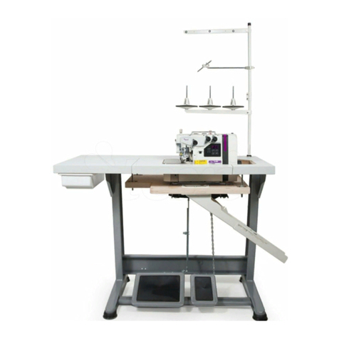
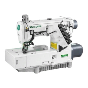
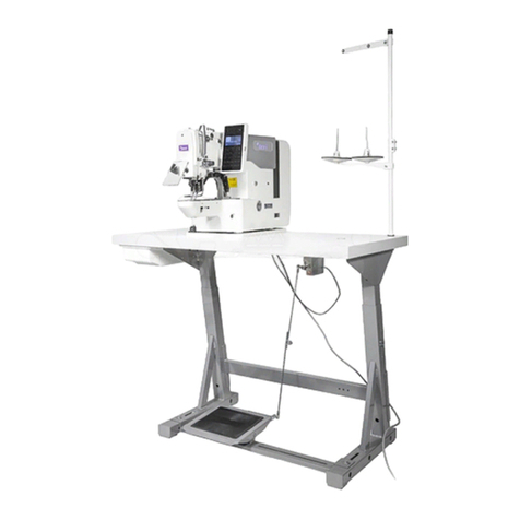
Texi 781 SERVO User manual

Operation Manual –TEXI 781 SERVO
Operation Manual
Buttonhole machine
781 SERVO

Operation Manual –TEXI 781 SERVO
Table of Contents
1. The height of the needle bar
2. The cooperation of the needle and the hook
3. Matching of the baseline adjustment handle
4. The needle bar cooperation
5. The adjustment of the needle drop
6. The height of the needle bar swing fork
7. The position of the under feeding crank
8. Front and rear position of the presser foot
9. Cutter falling time
10. The position of the cutter falls
11. Knife of action hook position
12. Adjustment of the stop device
13. Start the position of the security hook
14. The amount of back and forth movement of the upper knife
15. Left and right position of the upper knife
16. Height of the upper scissors
17. The position of the roll into the upper thread at the start of sewing
18. The time when the scissors are opened
19. Adjustment of the limit plate
20. Safety crank adjustment
21. Upper scissors spring pressure
22. Fixed knife position
23. Height of the presser plate
24. Low speed bump position
25. Starting lever and starting ram position
26. Belt adjustment
The adjustment of other parts
1. Adjust the position of the left and right stitches according to the width of the hole:
2. Adjustment of the tension opening time
3. Adjustment of the wiper
4. Adjustment of thread adjustment hook
5. Lower thread lever adjustment
6. Lower thread tension spring
7. Adjustment of the bobbin pressure bar device
1. The height of the needle bar:
Adjustment requirements:
When the needle bar is at the lowest point, the distance between the lower end surface of the
needle bar and the upper plane of the needle plate is 11.9 mm.
Operation Manual –TEXI 781 SERVO
Adjustment method:
(1) Insert the positioning ruler between the needle bar and the needle plate, loosen the needle bar,
and tighten the screws to adjust.
Note: the needle should fall in the center of the needle plate.
The phenomenon when the adjustment value changes:
When sewing elastic fabric, the needle bar is lowered a little more than the standard value, and
the effect is better.
2. The cooperation of the needle and the hook:
Adjustment requirements:
When the needle bar is lifted by 2.3mm from the lowest point, the center of the hook tip and the
needle should be the same, and the upper end of the needle eye is 1.6~1.8mm; the lateral gap
between the needle and the hook tip is about 0.05mm.
Adjustment method:
(1) With the needle bar rising from the lowest point, place the positioning scale 2 between the
needle bar and the needle plate, and then loosen the set screw of the hook sleeve to adjust.
(2) At this time, adjust the lateral clearance of the needle and the hook tip to about 0.05 mm,
and swing it to the left and right to check and not touch.

Operation Manual –TEXI 781 SERVO
(3) At this time, adjust the gap between the hook positioning hook and the hook to 0.5mm, and
loosen the screw of the hook positioning hook to adjust. (Keep the line pass smoothly)
The phenomenon when the adjustment value changes:
(1) When sewing elastic fabric, slow down the cooperation time of the hook to the needle, and
the effect is better. (The distance between the tip of the hook and the upper end of the needle eye
is about 1.0mm)
3. Matching of the baseline adjustment handle (adjusting the parallel gap between the cutter and
the left and right amplitudes)
Adjustment requirements:
(1) Position of the parallel portion on the left side: The lower end of the left baseline adjustment
screw is 10 mm from the upper plane of the baseline adjustment handle, and the lower plane of
the baseline adjustment handle is exposed to be about 1 mm.
(2) Position of the right parallel portion: The adjustment of the right baseline should be
adjusted to the A=B position according to the amplitude of the parallel portion.
Adjustment method:
(1) Adjustment of the left baseline should be performed when the needle falls in the center of the
needle plate hole. The distance between the lower end of the left baseline adjustment screw
and the plane above the baseline adjustment handle is approximately 10 mm, which is adjusted
by the left baseline adjustment screw (see figure).
(2) The adjustment of the right baseline is performed with the right baseline adjustment screw.
(3) Adjust the left and right baselines so that the cutter falls in the center of the parallel portion.

Operation Manual –TEXI 781 SERVO
(4) Adjustment order of amplitude and baseline: 1 change of course amplitude 2 Observation of
the distance between the inside of the amplitude of the right course and the falling point of
the cutter 3 Adjusting the position of the right baseline 4 Adjusting the amplitude of the
reinforcement
The phenomenon when the adjustment value changes:
When adjusting the left and right baselines, it is biased toward either side, and the stitches
adjacent to the parallel portion of the cutter may be biased to the inner side.
When the amplitude is increased, the left parallel portion is individually biased to the left.
4. The needle bar cooperation:
Adjustment requirements:
(1) When the needle is at the top center, the engraved line of the pinion gear should be aligned
with the center of the lower shaft.
(2) If there is no engraving on the pinion gear, when the needle bar is at the lowest point, the
center of the oil hole on the convex arc of the large arc of the needle pendulum (ie the center of
the convex arc of the cam) is aligned with the needle bar. Swing the left side of the plane (viewed
from the front).
Adjustment method:

Operation Manual –TEXI 781 SERVO
Loosen the fixing screw of the pinion gear to adjust the above standard adjustment value.
Pay attention to the axial movement of the lower shaft when adjusting. Confirmation method after
adjustment: pad the paper at the needle drop and turn the pulley by hand to observe whether there
is a lateral flow needle phenomenon on the needle drop point on the paper, that is, to ensure that
the swing of the needle before the needle bar is lowered to the front of the puncturing cloth should
end.
The phenomenon when the adjustment value changes:
When the reticle is missed, it will cause the needle to flow, the needle to break, and the needle to
jump.
5. The adjustment of the needle drop (for the needle board)
Adjustment requirements:
When sewing the parallel portion on the left side, the swing fork is at the leftmost end when the
needle is lowered to the middle portion of the needle plate hole.
Adjustment method:
When the position of the needle bar swing fork is normal, and the needle drop point is not correct,
the tightening screw of the crank shaft after the swing shaft can be loosened to be corrected.
The phenomenon when the adjustment value changes:
If the needle drop point is wrong, it will increase the needle swing amplitude, and the inaccurate
one will hit the needle plate hole and cause the needle break or thread break.
6. The height of the needle bar swing fork Adjustment requirements:

Operation Manual –TEXI 781 SERVO
When the machine is in the parking position (the needle is in the left needle position), loosen the
fastening screw on the baseline adjustment handle, push down the needle bar swing fork, so that
the large arc of the needle swing cam is convex to the top of the needle bar swing fork About
5mm, adjust the shank to the baseline adjustment shank, and then tighten the baseline adjustment
shank.
Note: When making this adjustment, please remove the spring of this mechanism and adjust it.
Check if the needle-swing cam of the needle-spindle gear rotates smoothly.
The phenomenon when the adjustment value changes:
If the height of the needle bar swing fork is not accurate, the width of the left and right courses
will be different.
7. The position of the under feeding crank
Adjustment requirements:
Even if the sewing size (adjustment button hole length) is changed, the position of the
presser foot does not change during parking, and the position of the feed carriage does not change.

Operation Manual –TEXI 781 SERVO
Adjustment method:
Rotate the main cam with the manual feed handle. When the main cam engraving line is aligned
with the center of the roller pin screw of the feeding lower crank, loosen the fastening screw of
the lower crank and then loosen the button hole length nut. When the plate moves to a distance
of 2.5mm from the needle plate (see picture), move the button hole length adjustment screw in
the arc groove of the feed crank body. If the presser foot does not move back and forth, the
position of the crank under the feed is correct. When the crank body does not move, tighten the
fastening screw of the lower crank.
The phenomenon when the adjustment value changes:
If the position is wrong, whenever the sewing size is changed, the action of the scissors will
fail, and the position of the presser foot will also change, causing a broken needle or thread
broken.
8. Front and rear position of the presser foot
Adjustment requirements:
The gap between the center of the needle drop hole and the inner end surface of the presser foot is
2.5 mm (when the vehicle is parked), and the presser foot plate is located at the same position on
both sides of the needle blade slot.
Adjustment method:
When the machine is in the parking position, loosen the fastening screws of the pallet to adjust.
Confirmation after adjustment: Please confirm that the lifting arm is
perpendicular to the bottom plate.
The phenomenon when the adjustment value changes:

Operation Manual –TEXI 781 SERVO
(1) If the position of the presser foot is not accurate, the front and rear positions of the presser
foot are not accurate, and the opening and closing action of the upper scissors action plate is
affected.
(2) When the parking is stopped, the gap between the center of the needle hole and the presser
foot is too small. When the sewing machine is in contact with the presser foot during sewing, the
thread is broken and the needle is broken.
9. Cutter falling time
Adjustment requirements:
After the sewing machine is completely decelerated, it will fall 2~3 before the stop (1 2 3 pin is
the reference).
Adjustment method:
Move the cutter action bump position and adjust the cutter fall time to 2~3 stitches before the
sewing machine stops.
Moving in the direction of the mark, the cutter falls early.
Note: When the number of stitches is adjusted to 93 or less, adjust the low speed bumps.
The phenomenon when the adjustment value changes:
When the cutter is operated during high-speed operation, the cutter will not fall, and the cutter
will be accelerated.
10. The position of the cutter falls
Adjustment requirements:
Should fall in the middle of the needle plate slot.
Adjustment method:
Loosen the needle plate seat fastening screw and move the needle plate seat position to adjust.
The phenomenon when the adjustment value changes:
When the position is wrong, the cutter hits the needle plate.
11. Knife of action hook position
Adjustment requirements:
The clearance between the cutter drive lever and the knife of action hook at the lowest point is
0.05~0.2mm.

Operation Manual –TEXI 781 SERVO
Adjustment method:
Use the knife of the drive hook adjustment screw to adjust.
The phenomenon when the adjustment value changes:
(1) When the cutter does not return or continuously falls, check the gap between the cutter
drive lever and the cutter action hook, or change the cutter drive lever tension spring.
(2) The cutter often does not fall down, and it is not possible to drop the knife at a low speed.
It may be that the tension spring of the cutter driving claw is insufficient. (replace the tension
spring)
12. Adjustment of the stop device
Adjustment requirements:
The clearance between the stop sub-block A and the stop lever block B is 0.2 to 0.5 mm (when
parked).
Adjustment method:
(1) Move the stop block A up and down to adjust.
(2) Adjustment of the stop buffer rod spring: When the hex nut is adjusted to the stop buffer
rod to expose 5mm, tighten it.

Operation Manual –TEXI 781 SERVO
Adjusted confirmation method:
The stop frame is adjusted to a high speed running state, and the manual stop handle is rotated,
the stop block must release a first gear, enter a low speed state, and then release the second gear
to enter a stop state.
The phenomenon when the adjustment value changes:
(1) At the parking position, the clearance between the stop sub-block A and the stop lever block
B is too small, and there is no stopping.
(2) When the hex nut loosens and the sewing machine stops, the height of the needle changes.
13. Start the position of the security hook
Adjustment requirements:
When parking, the distance between the start safety hook and the lifter lever is 0.5~0.8mm.
Adjustment method:
Adjust with the rotating eccentric shaft screw.
The phenomenon when the adjustment value changes:
If there is no gap, it will be in a state of conflict, causing the presser foot not to return. On the
contrary, if the gap is too large, it will not stop.
14. The amount of back and forth movement of the upper knife
Adjustment requirements:
The amount of back and forth movement is 4~5mm.
Adjustment method:
(1) Loosen the roller shaft fixing screw in front of the presser foot connecting rod, adjust the
amount of back and forth movement of the upper knife, move to the right to increase the
amount of movement, and shift to the left to decrease.

Operation Manual –TEXI 781 SERVO
(2) Note: The adjustment of this part is a slight adjustment, please do not adjust excessively
The phenomenon when the adjustment value changes:
When the amount of front and rear movement is excessively adjusted, the protruding portion of
the scissor swing frame will slide out from the groove of the presser roller frame. Once it is
slipped out, the presser foot cannot be lifted and the feeding becomes heavy.
15. Left and right position of the upper knife
Adjustment requirements:
(1) The upper scissors is aligned with the center of the needle when it advances to the foremost
end; and the front end of the scissors protrudes 5 mm to the right from the center of the cutter
groove.
(2) When the upper scissors is closed, the overlap between the upper knife and the lower knife is
0.5~0.8mm. Please note that there is still a gap even if it is closed.

Operation Manual –TEXI 781 SERVO
Adjustment method:
(1) Step on the presser foot pedal. When the upper thread scissors move to the apex, use a hex
wrench to loosen the fixing screws of the scissors pendulum and adjust the position of the front,
back, left and right.
(2) Loosen the fixing screw of the upper scissors action plate A and adjust the amount of
overlap between the upper knife and the lower knife.
The phenomenon when the adjustment value changes:
(1) When the front, back, and left and right positions are not good, when the presser foot is
raised, the scissors swing frame is caught and cannot move smoothly.
(2) The position of the scissors action board A is too far forward to produce the upper line cut
continuously. (scissors are not close together)
(3) When the position of the scissors action board A is too backward, the scissors will be closed
when the line is not clamped.
16. Height of the upper scissors

Operation Manual –TEXI 781 SERVO
Adjustment requirements:
Install the scissors as low as possible, but do not touch the presser foot.
Adjustment method:
Loosen the fixing screws of the upper scissors and adjust them up and down. Confirmation
method after adjustment: Place a gasket with a thickness of about 4 mm under the presser foot.
When moving the presser foot lever up and down, the presser foot and the scissors should not
touch each other.
The phenomenon when the adjustment value changes:
The position of the scissors is too high, and sometimes the thread will remain on the knot. 17.
The position of the roll into the upper thread at the start of sewing
Adjustment requirements:
At the beginning of the sewing, the top end of the upper scissors leaves the center of the needle
cutter slot 0 to 1 mm to the left. Adjustment method:
This position is adjusted by increasing or decreasing the number of wire head control pad spacers.

Operation Manual –TEXI 781 SERVO
Note: There is also a relationship with the position where the upper scissors clamps the wire, so
confirm the position of the upper scissors action plate, and then increase or decrease the wire
control plate gasket.
The phenomenon when the adjustment value changes:
The upper scissors is too far to the right and the upper line will be beyond the right side of the
stitch. On the contrary, the upper line will be beyond the left side of the stitch.
18. The time when the scissors are opened Adjustment
requirements:
Adjustment method:
(1) Loosen the wire head control plate fixing screw and move the control board back and
forth to adjust.
(2) The time to move the control board forward to clamp the upper line is longer, and on the
contrary, it is shortened.
Confirmation method after adjustment:
After adjustment, turn the manual feed handle, you must check that the scissors do not touch the
presser foot and needle when opening.
The phenomenon when the adjustment value changes:
(1) When the upper scissors is opened quickly, it may cause sewing not good and off-line when
the needle is lifted.
(2) When the upper scissors are opened slowly, the stitching is not good at the beginning of
the sewing.
19. Adjustment of the limit plate

Operation Manual –TEXI 781 SERVO
Adjustment method:
Loosen the limit plate fixing screw so that the sewing machine is in a state of low speed start
(when the stop block
A and the stop lever block B meet) the safety lever is in light
contact with the limit plate.
Adjusted confirmation method:
(1) When the safety lever is pressed toward the mark in the high-speed start state, there should
be no gap in the long hole at the safety pusher shaft screw.
(2) There should be a gap between the safety lever and the limit plate when parking and upper
scissors moving.
The phenomenon when the adjustment value changes:
Note: After an emergency stop, the presser foot should be raised at the needle up position.
20. Safety crank adjustment
Adjustment method:
After the upper scissors shaft is pulled away from the thread control board, the overlap between
the safety crank and the safety bump is 0.5 mm when the scissors are opened.
The phenomenon when the adjustment value changes
If it does not engage, the opening action of the scissors is not good.
21. Upper scissors spring pressure

Operation Manual –TEXI 781 SERVO
Adjustment method:
(1) When the upper thread scissors are loose, move the front of the scissors
spring with the hand plate.The front of the upper scissors spring and the scissors
mouth are all attached, and the thread can be clamped regardless of where the
scissors cut the thread.
(2) When the upper scissors edge is not sharp, the scissors can be replaced.
22. Fixed knife position
Adjustment requirements:
The fixed knife edge is 0.3~0.5mm away from the needle plate hole.
Adjustment method:
(1) Loosen the fixed knife fixing screw for the fixed knife adjustment.
(2) When changing the fixed knife, take out the hook finger to replace it.
The phenomenon when the adjustment value changes:
The gap between the fixed knife and the hole of the needle plate is too narrow, and it is easy to
break when sewing.
23. Height of the presser plate

Operation Manual –TEXI 781 SERVO
Adjustment requirements:
The lifting amount of the presser foot is 12mm
Adjustment method:
Insert the 12mm pad between the presser foot and the needle plate, loosen the presser foot fixing
screw, press the presser foot lifting pedal, and press the presser foot clamp and the presser foot
roller frame, then tighten the presser foot fixing screw .
Confirmation after adjustment: After adjustment, it must be confirmed that the presser foot can
work normally.
24. Low speed bump position
Adjustment method:
Adjust the size of A according to the number of stitches used to loosen the fixing screws of the
low-speed bumps.
stitches
A size
under 93 stitches
10~12mm
between 93-123
5mm
More than 123 stitches
0
The phenomenon when the adjustment value changes:
Moving the low-speed bumps counterclockwise can reduce the number of stitches from low speed
to stop.
25. Starting lever and starting ram position
Adjustment method:
When the machine is stopped, the gap between the end of the adjusting screw on the starting ram
and the stop frame is 0.5~1mm; the gap between the starting lever and the convex surface of the
fuselage base is 3mm.

Operation Manual –TEXI 781 SERVO
The phenomenon when the adjustment value changes:
If the gap at the starting ram is too large, it cannot be rotated at a high speed. If it is small, it will
cause an inaccurate stop.
26. Belt adjustment
Head start fork position:Adjustment
method:
When idling, the belt is exposed from the runner by about 0.5~1mm, which is adjusted by the
long hole of the starting fork (on the nose). At low speed, the belt should completely cover the
drive pulley.
Note: When idling, try not to make the belt contact the starter fork (on the handpiece).
The phenomenon when the adjustment value changes:
When idling, if the belt is wrapped around the drive pulley, the belt will be easily worn and the
pulley will heat up.
Speeding mechanism fork position Adjustment
method:

Operation Manual –TEXI 781 SERVO
Same as the adjustment method of the head start fork. When the low speed is running, loosen the
fixing screw of the speed reduction mechanism fork and adjust the position of the speed reduction
mechanism fork. However, adjust the limit screw at high speed.
The standard movement of the fork is 14mm. Adjust the pad with the shift fork to adjust. When
you spin it out, the stroke is reduced.
Note: If the fork is swung too far at low speed and parking, the fork cam is not properly installed.
Therefore, the fork cam should be installed parallel to the processing surface of the fork cam
holder.
The phenomenon when the adjustment value changes:
When the speed adjustment mechanism fork adjustment is not possible, please adjust the fork
adjustment pad.
The adjustment of other parts
1. Adjust the position of the left and right stitches according to the width of the hole:
(1) Swing of the needle: based on the right side,Sew the needle to the left side for sewing.In the
figure, A is the left baseline, B is the right baseline, W1 is the left and right horizontal
amplitude width, W2 is the reinforcement amplitude width, C is the first reinforcement
length (first set), and D is the second reinforcement length (second set) ).
(2) Adjustment of left baseline and right baseline
1 Rotate the adjusting screw 1, and the left baseline moves to the left; when the adjusting screw
1 is unscrewed, the left baseline moves to the right, but even if the amplitude is changed, the left
baseline A hardly needs to be adjusted. 2 Screw in the screw 2, the right baseline will move to
the left, and when it is rotated, it will move to the right.
Adjustment of horizontal width and reinforcement width
1Rotate the adjustment screw 3, the width of the course will increase, and the rotation will
decrease.
Table of contents
Other Texi Sewing Machine manuals

Texi
Texi Ziggy User manual

Texi
Texi CINQUE 35 N PREMIUM EX User manual

Texi
Texi Tronic 5 User manual

Texi
Texi 1501 TS PREMIUM User manual

Texi
Texi Compacta User manual

Texi
Texi Black&White User manual

Texi
Texi Art Auto 2 User manual

Texi
Texi Forte UF User manual

Texi
Texi Joy 13 User manual

Texi
Texi Joy 25 User manual