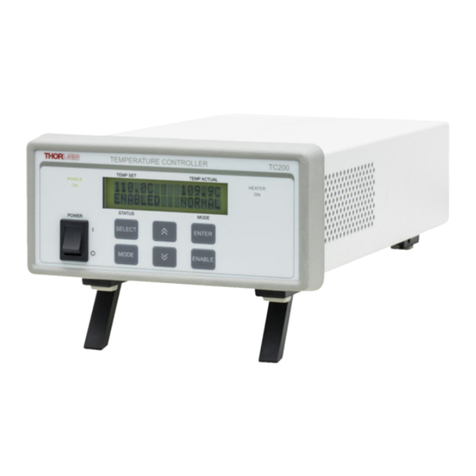
THORLABS T-Cube TTC001 User manual

HA0189T
TTC001
T-Cube TEC Controller
Kinesis User Guide
Original Instructions

T-Cube Laser Diode Driver
Contents
Chaper 1 Overview .................................................................................................. 1
1.1 Introduction ........................................................................................ 1
1.2 TEC Element Protection .................................................................... 2
1.3 Power Options .................................................................................... 3
1.4 -Kinesis Software Overview ............................................................. 3
1.4.1 Introduction ............................................................................................. 3
1.4.2 Kinesis Server ........................................................................................ 4
1.4.3 Software Upgrades ................................................................................. 5
Chaper 2 Safety .......................................................................................................... 6
2.1 Safety Information ............................................................................. 6
2.2 General Warnings .............................................................................. 6
Chaper 3 Getting Started ........................................................................................... 7
3.1 Install The Software ........................................................................... 7
3.2 Mechanical Installation ...................................................................... 7
3.2.1 Environmental Conditions ....................................................................... 7
3.2.2 Mounting Options ................................................................................... 8
3.2.3 Removing the Baseplate ........................................................................ 8
3.2.4 Using the TTC001 Controller on the KCH Series Hub ........................... 9
3.3 Electrical Installation ....................................................................... 10
3.3.1 Rear Panel Connector Identification ..................................................... 10
3.3.2 Connecting The TEC Element and Temperature Sensor ..................... 10
3.3.3 Connecting a Thermistor ...................................................................... 11
3.3.4 Connecting a Temperature Sensor AD590/AD592 .............................. 11
3.3.5 Checking the TEC polarity .................................................................... 12
3.4 Supply Voltage and Current Requirements ................................... 12
3.5 Connecting To A Standalone Power Supply ................................. 13
3.6 Connect The Hardware .................................................................... 13
3.7 Verifying Software Operation ......................................................... 15
Continued...

T-Cube Laser Diode Driver
Chaper 4 Standalone Operation .............................................................................. 16
4.1 Control Panel Buttons and Indicators .......................................... 16
4.2 Output Potentiometer Operation .................................................... 17
4.3 Navigating The Menus ..................................................................... 17
4.3.1 SETUP Menu Overview ........................................................................ 18
4.3.2 Selecting Display Value ........................................................................ 19
4.3.3 Setting the Sensor Type" ...................................................................... 20
4.3.4 Setting the TEC current limit "Cur L" .................................................... 21
4.3.5 Adjusting the Temperature Control Loop .............................................. 22
4.3.6 Control Loop Adjuestment - Recommended Procedure ....................... 23
4.3.7 Setting the Display Brightness .............................................................. 23
4.3.8 Storing and Recalling Control Parameters ........................................... 24
4.3.9 Analog Control of the Temperature ...................................................... 25
4.4 Typical Operation of the Temperature Controller ......................... 27
Chaper 5 Operation - Tutorial ................................................................................. 29
5.1 Introduction ...................................................................................... 29
5.2 Using the Kinesis Software ............................................................. 29
5.3 Typical Operation From the GUI Panel .......................................... 30
Chaper 6 Software Reference ................................................................................. 31
6.1 GUI Panel .......................................................................................... 31
6.2 Settings Panel .................................................................................. 33
6.2.1 Control Tab .......................................................................................... 33
6.2.2 Advanced Tab ...................................................................................... 34
Appendices
Appendix A Connector Pinout Details ....................................................... 35
Appendix B Preventive Maintenance ......................................................... 36
Appendix C Specifications and Associated Parts .................................... 37
Appendix D Regulatory ................................................................................ 40
Appendix E Thorlabs Worldwide Contacts ................................................ 41

Page 1 16005-D03
T-Cube TEC Controller
Chapter 1 Overview
1.1 Introduction
The T-Cube Thermoelectric Temperature Controller (TTC001) is a precise
temperature controller for laser diodes and detectors. The TTC001 is ideally suited
for:
• Wavelength Stabilization of Laser Diode
• Noise Reduction of Detectors
• Wavelength Tuning by Regulating the Temperature
• Modulation of Wavelength by Tuning the Temperature
The unit is easy to use due to the clearly arranged controls on the front panel. The
measurement values are shown by a 5-digit LED display and are selected via two
push buttons and a knob.
The TTC001 is designed to be completely compatible with Thorlabs T-Cube product
series. The unit can be controlled via the panel buttons or from a PC via the a USB
connection (either standalone operation or when mounted to the KCHx01 K-Cube
Hub). The operation can be controlled using the provided software package.
Fig. 1.1 T-Cube TEC Controller (TTC001)
The proportional gain, the integral share, and the de rivative share of th e PID
temperature control loo p can be set independent of each othe r to optimize the
performance of the co ntroller. The TTC001 also has preloaded setups for each of
Thorlabs' TEC mounts to simplify operation. No PID adjustments should be needed
for Thorlabs' LDM56, LDM90, LM14S2, and LDM21.

Rev A Nov 2017 Page 2
Chapter 1 Overview
For temperature sensi ng the TTC001 temperature controller works with both
thermistors and temperature IC sensors like the AD590 or AD592. With a thermistor
the temperature display is shown as resistance value in kΩ. If the TTC001 is operated
with a temperature sensor IC, the temperature is shown in °C or °F.
TEC current output can be enabled or disabled via the Enter button on the front panel.
The Mode button allows the user to access the setup menus. The front panel Control
Knob can be used to adjust the temperature setting as well as navigate the menu.
The temperature sensor and the TEC element are connected by a 15-pin D-sub jack
at the rear of the unit. A 15-pin D-sub to 9-pin D-sub is supplied with the TTC001 to
directly connect to Thorlabs LDM56, LDM90, LDM21 and LM14S2 TEC mounts.
The set value of the temperature can be changed with the Control Knob on the front
panel or through the provide software when connected through the USB port. Also,
an analog input can be used to set the set point temperature or to directly control the
output current level. The temperature set point option will scale the input from the
lower temperature limit to the upper temperature limit. Th ese limits are set in the
Setup Menu. For current control, the input will scale to the current limit also set in the
setup menu.
The unit has been designed for safe operation with environmental temperatures up to
40 °C provided that a free air circulation through the ventilation slots at the rear and
at both sides of the unit is maintained.
USB connectivity provides easy Plug and Play PC controlled operation - multiple units
can be connected to a single PC via standard USB hub technology or by using the K-
Cube Controller Hub (see Section 3.2.4.) for multi-axis motion control applications.
Coupling this with the user friendly Kinesis™ software (supplied) allows the user to
get up and runn ing in a short space of time. Advanced custom motion control
applications and sequences are also possible using the extensive programming
environment also supplied. This programming library is co mpatible with ma ny
development tools such a s LabView, Visual Basic, Visual C++, C++ Builder,
LabWindows/CVI, Matlab and Delphi.
See Section 1.4. for a full description of the Kinesis software.
In the remainder of this handbook, the Tutorial section (Chapter 5) provides a good
initial understanding on using the unit, and the reference section (Chapter 6) covers
all operating modes and parameters in detail.
1.2 TEC Element Protection
The temperature control system includes a protective ci rcuit, which limits the TEC
current in all operating modes.
The current limit can be set through the menu system via the front panel, and through
software method calls. The TTC001 has a maximum current limit of ±1 A but this can
be limited to a minimum of ±100 mA. To access this feature press the Mode button,
Adjust the Control Knob until "Cur L" appears, Press the Enter button, use the Control
Knob to select the desired limit, and press Enter to accept.
Page 3 16005-D03
T-Cube TEC Controller
When the unit is first turned on, the TEC current will be disabled. Pressing the Enter
button allows the TEC controller to enable / disable the current. When the TEC current
is disabled, the display will blink with the set temperature displayed.
1.3 Power Options
A compact power supply unit (TPS101) is available from T horlabs for powering a
single TTC001 unit. This power supply unit is also designed to take up minimal space
and can be mounted to the optical table in close proximity to the driver units,
connected via short power leads. As a further level of convenience when using the T-
Cube Controllers Thorlabs also offers the 3-channel and 6-channel Controller Hubs
(KCH301 and KCH601). These products have been designed specifically with
multiple cube operation in mind in order to simplify issue s such as ca ble
management, power supply routing, multiple USB de vice communications and
different optical table mounting scenarios.
The K-Cube Controller Hub comprises a slim base-plate type carrier with electrical
connections located on the upper surface to accept the K-Cubes.
Internally the Controller Hub contains a fully compliant USB 2.0 hub circuit to provide
communications for all K-Cubes – a single USB connection to the Controller Hub is
all that is required for PC control. The Controller Hub also provides power distribution
for the K-Cubes, requiring only a single power connection..
1.4 -Kinesis Software Overview
1.4.1 Introduction
The K-Cube range of co ntrollers share many of the benefits. These include USB
connectivity (allowing multiple units to be used together on a single PC), fully featured
Graphical User Interface (GUI) panels, and extensive software function libraries for
custom application development.
The Kinesis software suite provides a flexible and powerful PC based control system
both for users of the equipment, and software programmers aiming to automate its
operation.
The User Interface allows full control of all settings and operating modes enabling
complete ‘out-of-box’ operation without the need to deve lop any further custom
software. It provides all of the necessary system software services such as generation
of GUI panels, communications handling for multiple USB units, and logging of all
system activity to assist in hardware trouble shooting. The Kinesis server is also used
by software developers to a llow the creation of advanced automated positioning
Caution
The KCH301 and KCH601 Controller Hubs have been designed primarily for
use with the K-Cube range of controller units. T-Cube controllers such as the
TTC001 TEC Controller can still be used on this hub, but will require an adapter
plate (KAP101) before they can be fitted - see Section 3.2.4. for more details.

Rev A Nov 2017 Page 4
Chapter 1 Overview
applications very rapidly and with great ease. The server is described in more detail
in the following section.
1.4.2 Kinesis Server
Kinesis controls are re-usab le compiled software compo nents that supply both a
graphical user interface an d a p rogrammable interface. Many such Controls a re
available for Windows applications development, providing a large range of re-usable
functionality. For example, there are C ontrols available that can be used to
manipulate image files, connect to the in ternet or si mply provide user interface
components such as buttons and list boxes.
With the Kinesis system, .Net Controls are deployed to allow direct control over (and
also reflect the status of) the range of electronic controller units, including the Piezo
K-Cube. Software applications that use .Net Controls are often referred to as 'client
applications'. A .Net Co ntrol is a l anguage independent software component.
Consequently the controls can be i ncorporated into a wide range of softwa re
development environments for use b y client application developers. Development
environments supported include Visual Basic, Labview, Visual C++, C++ Builder,
HPVEE, Matlab, VB.NET, C#.NET
and, via VBA, Microsoft Office applications such as
Excel and Word.
Consider the control supplied for a TTC001 TEC controller unit..
This Control provides a complete user graphical instrument panel to allow the TEC
unit to be manually operated, as well as a complete set of software functions (often
called methods) to allow all parameters to be set and TEC control operations to be
automated by a client application. The instrument panel reflects the current operating
state of the controller unit to which it is associated (e.g. such as actual temperature).
Updates to the panel take place automatically when a user (client) application is
making software calls into the same Control.

Page 5 16005-D03
T-Cube TEC Controller
The Kinesis software provides a rich set of graphical user panels and programmable
interfaces allowing users and client application developers to interact seamlessly with
the hardware. Each of the controllers has an associated GUI Control and these are
described fully in the handbook for the associated controller.
Fig. 1.2 System Architecture Diagram
Refer to the main Kinesis Software online help file, for a compl ete programmers
guide. This is available either by pressing the F1 key when running the Kinesis server,
or via the Start menu, Start\Programs\Thorlabs\Kinesis\Kinesis Help.
1.4.3 Software Upgrades
Thorlabs operate a policy of continuous product development and may issue software
upgrades as necessary. The latest software can be do wnloaded from the ‘services’
section of www.thorlabs.com.

Rev A Nov 2017 Page 6
Chapter 2 Safety
Chapter 2 Safety
2.1 Safety Information
For the continuing safety of the operators of this equipment, and the protection of the
equipment itself, the operator should take note of the Warnings, Cautions and Notes
throughout this handbook and, where visible, on the product itself.
The following safety symbols may be used throughout the ha ndbook and on the
equipment itself.
2.2 General Warnings
Warning: Risk of Electrical Shock
Given when there is a risk of injury from electrical shock.
Warning
Given when there is a risk of injury to users.
Caution
Given when there is a risk of damage to the product.
Note
Clarification of an instruction or additional information.
Warning
If this equipment is used in a ma nner not specified by the manufacturer, the
protection provided by the equipment may be impaired. In particular, excessive
moisture may impair operation.
Spillage of fluid, such as sample solutions, should be avoided. If spillage does
occur, clean up immediately using absorbant tissue. Do not allow spilled fluid to
enter the internal mechanism.

Page 7 16005-D03
T-Cube TEC Controller
Chapter 3 Getting Started
3.1 Install The Software
DO NOT CONNECT THE CONTROLLER TO YOUR PC YET
1) Go to Services/Downloads at www.thorlabs.com and download the Kinesis software.
2) Run the .exe file and follow the on-screen instructions.
3.2 Mechanical Installation
3.2.1 Environmental Conditions
Location Indoor use only
Maximum altitude 2000 m
Temperature range 5 oC to 40 oC
Maximum Humidity Less than 80% RH (non-condensing) at 31 °C
To ensure reliable operation the unit should not be e xposed to corrosive agents or
excessive moisture, heat or dust.
If the unit has been stored at a low temperature or in an environment of high humidity,
it must be allowed to reach ambient conditions before being powered up.
Note
This section is applicable only if the T-Cube is to be used with a PC. If your
application consists only of local operation via the T-Cube front face, proceed to
Section 3.6.
When operating via a PC, direct user interaction with the NanoTrak controller is
accomplished through intuitive graphical user interface panels (GUIs), which expose
all key operating parameters and modes. The user can select multiple panel views
displaying different information about a particular hardware unit. The multitasking
architecture ensures that the graphical control panels always remain live, showing
all current hardware activity.
Caution
Some PCs may ha ve been configured to restrict the users abi lity to load
software, and on these systems the software may not install/run. If you are in
any doubt about your rights to install/run software, please consult your system
administrator before attempting to install.
If you experience any problems when installing software, contact Thorlabs on
+44 (0)1353 654440 and ask for Technical Support.
Warning
Operation outside the foll owing environmental limits may ad versely affect
operator safety.

Rev A Nov 2017 Page 8
Chapter 3 Getting Started
3.2.2 Mounting Options
The T-Cube TEC Controller is shipped with a baseplate fitted, ready to be bolted to a
breadboard, optical table or similar surface.
If desired, the baseplate can be removed and the unit can be stood on rubber feet -
see Section 3.2.3.
For multiple cube systems, a 3-channel and 6-channel K-Cube Controller Hub
(KCH301 and KCH601). ) are also available - see Section 1.3. for further details. Full
instructions on the fitting and use of the controller hub are contained in the handbook
available at www.thorlabs.com.
3.2.3 Removing the Baseplate
The baseplate must be removed before the rubber feet (supplied) can be fitted, or the
unit is connected to the USB controller hub..
Fig. 3.1 Removing The Baseplate
1) Using a hexagon key, remove the bolts securing the unit to the baseplate. Retain
the bolts for future use if the baseplate is refitted.
2) Turn the unit upside down.
Caution
When siting the unit, it should be positioned so as not to impede the operation
of the control panel buttons.
Ensure that proper airflow is maintained to the rear and sides of the unit. Do not
obstruct the ventilation holes.
Detail A Detail B
Baseplate removed and rubber feet fittedBaseplate attachment screws

Page 9 16005-D03
T-Cube TEC Controller
3) Remove the backing paper from the rubber feet (supplied) taking care not to touch
the exposed adhesive surface.
4) Position the feet as desir ed, then press and hold for a few seconds until the
adhesive has bonded.
5) The unit may now be used freestanding, sitting on its rubber feet.
3.2.4 Using the TTC001 Controller on the KCH Series Hub
The KCH301 and KCH601 Controller Hubs have been designed primarily for use with
the K-Cube range of controller units. T-Cube controllers such as the TTC001 TEC
Controller can still be used on this hub, but will require an adapter plate (KAP101)
before they can be fitted. The baseplate must be removed as described previously,
before fitting the KAP101 adapter plate.
1) Ensure that all power is disconnected from the hub.
2) Remove the plastic cover from the relevent connector on the KCH hub.
3) Undo the plastic securing clips on each side of the hub at the position to be fitted.
4) Check for correct orientation of th e ERNI connector socket on the hub and its
mating plug on the adapter plate, then plug the adapter plate into the hub,
ensuring that the locating pegs on the hub are correctly fitted into the lugs in the
base of the adapter plate.
5) Do up the securing clip.
6) If fitted, remove the base plate from the T-Cube (see Section 3.2.3.). Retain the
screws for later use.
7) Check for correct orientation of the ERNI connector socket on the KAP101
adapter plate and its mating plug on the T-Cube unit, then plug the T-Cube unit
into the hub, ensuring that the locating pegs on the adapter plate are co rrectly
fitted into the lugs on the T-Cube.
8) Using the screws retained at item (6) secure the T-Cube to the adapter plate

Rev A Nov 2017 Page 10
Chapter 3 Getting Started
3.3 Electrical Installation
3.3.1 Rear Panel Connector Identification
Fig. 3.2 Rear Panel Connections
TEC OUTPUT (15-Pin D-Sub connector) – Provides connection to the Laser Diode
Mount or other device. If Laser Diode Mounts by Thorlabs are used, connect the
"TEC OUTPUT" of the TTC001 to the 9-pin plug "TEC DRIVER" of the Laser Diode
Mount, using the provided shielded cable CAB420-15.
With other equ ipment, connect the TEC element and the temperature sensor as
detailed in Appendix A.1
TUNE IN – Used to control the output of the controller from an external source. A zero
to 5 V analog input can be used to either adjust the set temperature, allowing the PID
loop to maintain the de sired temperature, or it can be used to d irectly control the
current output of the controller.
When used to adjust the set temperature, the maximum tuning range for the analog
control input "TUNE IN" is detailed in Section 4.3.9.
When directly controlling the current output, the current limit (iLim) is used to scale the
analog input so that the 0 to 5 V provides a range of ±iLim - Section 4.3.4.
3.3.2 Connecting The TEC Element and Temperature Sensor
If Laser Diode Mounts by Thorlabs are us ed, connect the "TEC OUTPUT" of the
TTC001 to the 9 -pin plug "TEC DRIVER" of th e Laser Diode Mount, using the
provided shielded cable CAB420-15.
The unit can also be used with any standard thermistor or AD590/AD592 temperature
sensors. Connect the TEC element and the temperature sensor as detailed in the
following sections.
For thermistors, a measurement range of 0 and 20.00 kΩ (TH20) or 0 and 200.0 kΩ
(TH200) can be selected - see Section 4.3.3. When AD590 (also AD592) temperature
sensors are connected, the measurement range is between -45.0 °C and +125.0 °C.
TTC001
TEC OUTPUT
1
9
TUNE IN
5V MAX

Page 11 16005-D03
T-Cube TEC Controller
The actual control range depends on the sensor ratings and the individual thermal
setup.
3.3.3 Connecting a Thermistor
The thermistor must be conn ected between pin 3 and pin 4 of the T EC OUTPUT
connector as detailed in Appendix A.1 The polarity is unimportant if the thermistor
is floating. If one pin of the thermistor is grounded (for example in a laser module), this
pin has to be connected to pin 3.
If the Temperature Controller TTC001 is operated with a the rmistor as the
temperature sensor, the set temperature and the actual temperature are displayed
in kΩ. From the "SEenSr" menu in the Setup Menu, select either ‘th20’ or ‘th200’ (see
Section 4.3.3.). This selects the resistance range of the thermistor between a
maximum thermistor resis tance of 20 kΩ (measurement current is 100 µA) and a
maximum thermistor resistance of 200 kΩ (measurement current is 10 µA).
In most cases a 10k thermistor will be used. In this case, the 20K range may be
selected but this will limit the actual temperature range to approximately 15 °C (see
thermistor operating curve for actual values). Usually this is sufficient but if
temperatures lower than 15 °C are required, the 200k range should be used. This will
lower the overall set point resolution but increase the operating range.
3.3.4 Connecting a Temperature Sensor AD590/AD592
If the temperature/current transducer AD590 (or AD592) is used as the temperature
sensor, it is connected between pin 10 (-) and pin 11 (+) of the TEC OUTPUT
connector as detailed in Appendix A.1 From the "SEnSr" menu in the Setup Menu,
select ‘Ad590’ (see Section 4.3.3.). The accuracy of the displayed temperature
depends on the tolerance of the transducer used.
Caution
A reverse poled TEC element may lead to thermal runaway and destruction of
the connected components. If there is any doubt concerning the TEC element
polarity, perform a polarity check as detailed in Section 3.3.5.

Rev A Nov 2017 Page 12
Chapter 3 Getting Started
3.3.5 Checking the TEC polarity
1) Connect power to the TTC001
2) Connect the temperature sensor to the jack "TEC OUTPUT" ?
3) Select the appropriate sensor type through the menu by pressing the Mode button
once and rotating the Control Knob un til "SEnSr" is displ ayed. Press the Enter
button and select the correct sensor wit h the Control Knob. Press Enter again.
Note: AD590 and AD592 are equivalent, select "Ad590" for either one. Once you
select the sensor type you will be able to set the temperature upper limits ("HI L")
and the temperature lower limit ("LO L").
4) Select a suitable current limit in the same way the sensor was selected. Enter the
"Cur L" menu and use the Co ntrol Knob to set the li mit. Press Enter when the
desired current limit is displayed.
5) Select the appropriate display type in the "diSP" menu using the Control Knob and
Enter button.
6) Press Mode to switch the display to the Monitor Mode. The display will be flashing
and will show the current set temperature.
7) Select a temperature setting that is higher or lower than ambient temperature with
the Control Knob and press Enter. Press Enter again to enable the TEC current.
The display should stop flashing. If t he TEC module is connected with the rig ht
polarity, the difference between the set value and the actual setting will decrease.
If the control loop parameters are set pr operly (refer to chapter 3.4), the actual
temperature will approach the set temperature in a short time. If the TEC module
is connected with wrong polarity, the difference between the set temperature and
the actual temperature will increase continuously. Switch off the TEC current by
pressing the Enter button and change the TEC module wiring at the D-sub plug
connected to the jack "TEC OUTPUT".
3.4 Supply Voltage and Current Requirements
Supply Minimum Maximum Max Operating Current
+5 V +4.9 V +5.1 V 1 A

Page 13 16005-D03
T-Cube TEC Controller
3.5 Connecting To A Standalone Power Supply
Fig. 3.3 Front Panel Power Supply Connector
1) Using the front panel connector as shown above, connect the unit to a regulated
DC power supply of +5 V, 1 A.
Thorlabs offers a si ngle way wa ll plug supply (TPS101) for po wering a sin gle
Driver T-Cube.
2) Switch on the Power Supply unit.
3) The Version number of the embedded software is displayed for a few seconds.
3.6 Connect The Hardware
Warning
The unit must be co nnected only to a DC supply as detailed in Section 3.4.
Connection to a supply of a different rating may cause damage to the unit and
could result in injury to the operator.
Caution
Do not connect the TEC unit to a 'live' external power supply. Doing so (i.e. “hot
plugging”) carries the risk of PERMANENT damage to the unit. Always ensure
the power supply unit is isolated from the mains before connecting to the TEC
unit. Always power up the TEC unit by connecting its power supply to the mains.
Similarly, to power down the unit, disconnect the power suply from the mains
before disconnecting the TEC unit.
USB
+5VDC 1A
THORLABS Inc
www.thorlabs.com
_+
POWER

Rev A Nov 2017 Page 14
Chapter 3 Getting Started
1) Perform the mechanical installation as detailed in Section 3.2.
2) Connect the laser mount or other device to the TEC Controller unit - see Section
3.3.1.
3) Connect the Controller unit to the power supply - see Section 3.5.
4) Connect the PSU to the main supply and switch ‘ON’. The version number of the
embedded software is displayed while the unit boots up. If the unit is being used
with the KCHx01 USB Controller hub, the bay ident number is also displayed. The
software version is useful when requesting technical support.
5) Connect the TEC Controller unit to your PC.
6) WindowsTM should detect the new hardware. Wait while WindowsTM installs the
drivers for the new hardware - see the Getting Started guide for more information.
7) For maximum accuracy, wait approximately 30 mins for the unit to thermally
stabalize to the environment.
8) Run the Kinesis software
Start/All Programs/Thorlabs/Kinesis/Kiesis.
9) Your T-Cube TEC Controller is now ready for use.
See Chapter 5 of this manual for a brief tutorial on operation of the unit.
Caution
During item (3) ensure the power supply unit is isolated from the mains before
connecting to the TEC unit. Always power up the TEC unit by connecting its
power supply to the mains. DO NOT connect the TEC unit to a 'live' external
power supply. Doing so (i.e. “hot plugging”) carries the risk of PERMANENT
damage to the unit. Similarly, to power down the unit, disconnect the power
suply from the mains before disconnecting the TEC unit.
Note
The USB cable should be no more than 3 metres in length. Communication lengths
in excess of 3 metres can be achieved by using a powered USB hub).

Page 15 16005-D03
T-Cube TEC Controller
3.7 Verifying Software Operation
1) Install the software as detailed in Section 3.1.
2) Connect the controller to the actuators (see Section 3.3.1.) and the PC, then
switch ON. Wait approximately 5 seconds for the system to settle.
3) Run the software and check that the Graphical User Interface (GUI) panel appears
and is active.
Fig. 3.4 Gui panel showing jog and ident buttons
4) Click the ‘Ident’ button. The Power LED and digital display on the front pa nel of
the associated controller flashes. This is u seful in multi-channel systems fo r
identifying which channel is associated with which GUI.
5) Click the jog buttons on the GUI pa nel to adjust the Set Temperature. The
temperature display on the associated TEC controller unit should increment and
decrement accordingly.
Follow the tutorial described in Chapter 5 for further guidance on basic operation.
Caution
In applications requiring the h ighest level of accuracy and repeatability, it is
recommended that the controller unit is powered up approximately 30 minutes
before use, in order to allow the internal temperature to stabilize.

Rev A Nov 2017 Page 16
Chapter 4 Standalone Operation
4.1 Control Panel Buttons and Indicators
Fig. 4.1 Panel Controls and Indicators
MAIN Display - Shows the Temperature Set Point applied to the TEC element.
OUTPUT Potentiometer - Used to the navigate the setup menus and to adjust
parameter settings.
MODE Button - Toggles between the Setup menu (see Section 4.3.) a nd the
Monitor mode.
ENTER Button - In Monitor mode used to enable or disable the TEC element or to
select a new desired temperature setting. In Setup mode used to select a new
menu item or parameter value.
POWER LED - Lit when power is applied to the unit.
Note
The POWER LED will flash when the ‘Ident’ button is clicked on the Software GUI
panel - see Section 6.1. for further details.
POWER
MODE
ENTER
OUTPUT
TEC controller

Page 17 16005-D03
T-Cube TEC Controller
4.2 Output Potentiometer Operation
The OUTPUT potentiometer is an infinite turn encoder, used to adjust the
temperature set poi nt. To increase the set point value, turn the potentiom eter
clockwise - once the maximum value (dependent upon the CUr L setting - see Section
4.3.4. and Section 6.2.) is attained, subsequent clockwise turns d o not effect the
output, however the value decreases immediately when the control is tu rned
anticlockwise. Similarly, once the set po int value has been decreased to zero,
subsequent anticlockwise turns do not effect the output, but the value increases
immediately when the control is turned clockwise.
4.3 Navigating The Menus
Pressing the ‘MODE’ button toggles the display between the Monitor Mode and the
Setup Menu.
In Monitor Mode, with the TEC current disabled, the display will be flashing the Set
Temperature. Press the Enter button to enable the TEC current. The display stops
flashing and shows the actual temperature, the current, or the difference between the
actual temperature and the set temperature. The displayed parameter is selected in
the Setup Menu - see Section 4.3.2.
When the TEC current is enabled, pressing the Enter button disables the TEC current
and the display will again flash the set temperature.
The set temperature can be chan ged by rotating the OUTPUT Knob while in the
Monitor Mode. If the T EC current is en abled, the display will temporarily switch to
show the current se t temperature and allow you to a djust it. Once the desired
temperature is displayed, press the Enter button to select it.
In the Setup Menu, the control knob will a llow you to navigate through the men u.
Once the desired menu item is displayed, it can be selected by pressing the Enter
button.
Some of the men u items ha ve sub menus that can also be n avigated using the
OUTPUT Knob. Other menu items allow you to adjust a value. The values can be
adjusted by rotating the OUTPUT Knob until the desired value is displayed and then
pressing the Enter button.
Pressing the Mode button while a menu value is displayed will return you to the menu
without adjusting the current value. If in a sub menu, pressing Mode will bring you
back up to the main Setup Menu.
Table of contents
Other THORLABS Temperature Controllers manuals

THORLABS
THORLABS ITC8000 User manual

THORLABS
THORLABS TED350 User manual

THORLABS
THORLABS TED4015 User manual

THORLABS
THORLABS TC300 User manual

THORLABS
THORLABS MTD415T User manual

THORLABS
THORLABS Blueline Series User manual

THORLABS
THORLABS TED8 Series User manual

THORLABS
THORLABS TCLDM9 User manual

THORLABS
THORLABS TC200 User manual

THORLABS
THORLABS TXP Series User manual