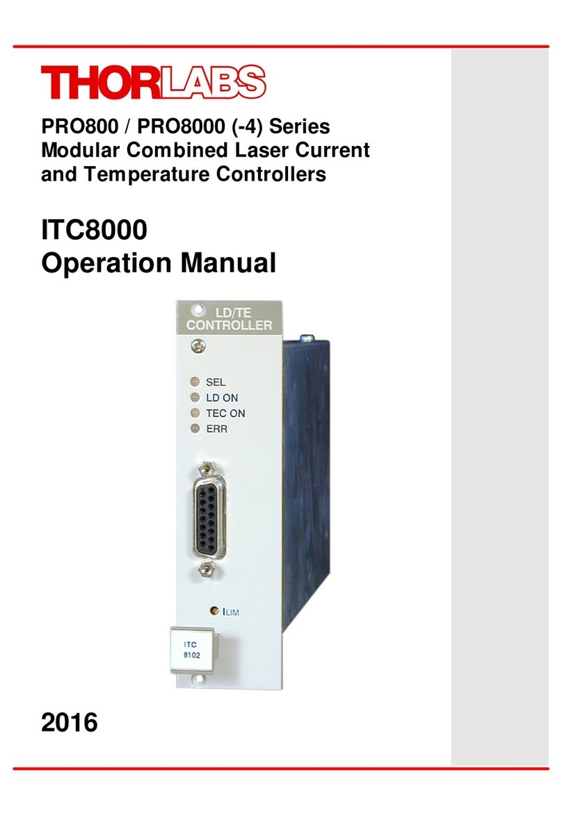
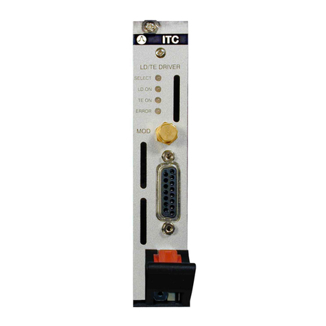
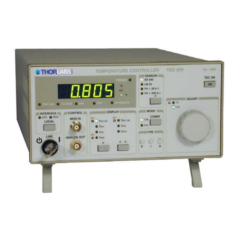
THORLABS TED8 Series User manual

-~
ARTISAN
®
~I
TECHNOLOGY
GROUP
Your definitive source
for
quality
pre-owned
equipment.
Artisan Technology
Group
Full-service,
independent
repair
center
with
experienced
engineers
and
technicians
on staff.
We
buy
your
excess,
underutilized,
and
idle
equipment
along
with
credit
for
buybacks
and
trade-ins
.
Custom
engineering
so
your
equipment
works
exactly as
you
specify.
•
Critical
and
expedited
services
•
Leasing
/
Rentals/
Demos
• In
stock/
Ready-to-ship
•
!TAR-certified
secure
asset
solutions
Expert
team
ITrust
guarantee
I
100%
satisfaction
All
tr
ademarks,
br
a
nd
names, a
nd
br
a
nd
s a
pp
earing here
in
are
th
e property of
th
e
ir
r
es
pecti
ve
ow
ner
s.
Find the Thorlabs / Profile PRO8000 at our website: Click HERE

Operation Manual
Thorlabs Blueline™ Series
PRO8000 (-4) / PRO800
Temperature module TED8xxx
2003

Version: 2.10
Date: 13.10.2003
Copyright©2003, Thorlabs GmbH

Contents page
1General description of the temperature module TED8xxx 1
1.1 Safety 1
1.2 Warranty 3
1.3 Features 4
1.3.1 Safety measures for the TEC element 4
1.3.2 General functions 6
1.4 Technical data 7
1.4.1 Common data TED8xxx 7
1.4.2 Technical data TED8xxx-Kryo (option) 8
1.4.3 TED8020 9
1.4.4 TED8040 9
1.4.5 TED8080 10
1.5 Operating elements on front panel 11
1.5.1 The TED8xxx module 11
1.5.2 The TED8080 module 12
1.6 Pre-settings 13
1.6.1 Setting the limit values 13
1.7 Connecting components 15
1.7.1 Pin assignment TED8xxx 15
1.7.2 Pin assignment TED8xxx-PT 16
1.7.3 Pin assignment TED8xxx-Kryo 17
1.7.4 Connecting a thermistor 18
1.7.5 Connecting an AD590 18
1.7.6 Connecting an LM335 19
1.7.7 Connecting a PT-100 or PT-1000 sensor (option PT or Kryo) 19
1.7.8 Connecting TEC elements with voltage detector 20
1.7.9 Polarity check of the TEC element 22
1.7.10 Connecting the status display 22
1.8 Optimization of temperature control 23
1.8.1 Principle set-up and function 23
1.8.2 PID adjustment 24
2Operating the TED8xxx 26
2.1 Functions in the main menu 26
2.1.1 Display 26
2.1.2 Selecting a module 27
2.1.3 Setting the temperature 27
2.2 Functions in the channel menu 29

2.2.1 Display 29
2.2.2 Changing parameters 31
2.2.3 Selecting the type of the sensor 32
2.2.4 Selecting the range of a thermistor 33
2.2.5 Selecting the range of the Pt-1000 (Kryo-option) 33
2.2.6 Calibrating the thermistor 34
2.2.7 Calibration of the Pt-1000 sensor (Kryo option) 37
2.2.8 Setting a temperature window 38
2.2.9 Setting the P-, I- and D-share of the control loop 38
2.3 Switching on and off 40
2.4 Error messages 41
3Communicating with a control computer 43
3.1 General notes on remote control 43
3.1.1 Nomenclature 44
3.1.2 Data format 44
3.2 commands 46
3.2.1 Select the module slot 46
3.2.2 Thermistor calibration (exponential method) 46
3.2.3 Thermistor calibration (Steinhart-Hart method) 48
3.2.4 Switching the I-share on and off (INTEG) 49
3.2.5 Reading the TEC current (ITE) 49
3.2.6 Programming the TEC current software-limit (LIMT) 50
3.2.7 Reading the TEC current hardware-limit (LIMTP) 51
3.2.8 Programming the resistance of the temperature sensor (RESI) 52
3.2.9 Programming the resistance window (RWIN) 53
3.2.10 Selecting the sensor (SENS) 54
3.2.11 Programming the PID shares (SHAREP, -I, -D) 55
3.2.12 Switching the TEC on and off (OUTP) 56
3.2.13 Programming the temperature (TEMP) 57
3.2.14 Programming the temperature window (TWIN) 58
3.2.15 Reading the TEC voltage (VTE) 59
3.3 1100 ... 1199 TED8xxx error messages 60
3.4 Status reporting 61
3.4.1 Standard event status register (ESR) 63
3.4.2 Standard event status enable register (ESE) 63
3.4.3 Status byte register (STB) 64
3.4.4 Service request enable register (SRE) 64
3.4.5 Reading the STB by detecting SRQ 65
3.4.6 Reading the STB by "*STB?" command 65

3.4.7 Reading the STB by serial poll 65
3.4.8 Device error condition register (DEC) 66
3.4.9 Device error event register (DEE) 66
3.4.10 Device error event enable register (EDE) 67
4Service and Maintenance 68
4.1 General remarks 68
4.2 Troubleshooting 69
5Listings 71
5.1 List of abbreviations 71
5.2 List of figures 73
5.3 Certifications and compliances 74
5.4 Addresses 75

We aim to develop and produce the best solution for your application in the
field of optical measurement technique. To help us to come up to your
expectations and develop our products permanently we need your ideas and
suggestions. Therefore, please let us know about possible criticism or ideas.
We and our international partners are looking forward to hearing from you.
In the displays shown by the PRO8 you may find the name PROFILE.
PROFILE was the name of the manufacturer before it was acquired by Thorlabs
and renamed to Thorlabs GmbH.
Thorlabs GmbH
This part of the instruction manual contains every specific information on how to
operate a temperature module TED8xxx. A general description is followed by
explanations of how to operate the unit manually. You will also find every information
about remote control via the IEEE 488 computer interface.
!Attention!
This manual contains “WARNINGS” and “ATTENTION” label in this
form, to indicate dangers for persons or possible damage of equip-
ment.
Please read these advises carefully!
NOTE
This manual also contains “NOTES” and “HINTS” written in this form.

1.1 Safety
Temperature module TED8xxx / page 1
1 General description of the temperature module TED8xxx
1.1 Safety
!Attention !
All statements regarding safety of operation and technical data in
this instruction manual will only apply when the unit is operated
correctly.
Before applying power to your PRO8000 (-4) / PRO800 system, make
sure that the protective conductor of the 3 conductor mains power
cord is correctly connected to the protective earth contact of the
socket outlet!
Improper grounding can cause electric shock with damages to your
health or even death!
Modules may only be installed or removed with the mainframe
switched off.
All modules must be fixed with all screws provided for this purpose.
Modules of the 8000 series must only be operated in the mainframe
PRO8000, PRO8000-4 or PRO800.
All modules must only be operated with duly shielded connection
cables.
Only with written consent from Thorlabs may changes to single
components be carried out or components not supplied by Thorlabs
be used.
This precision device is only dispatchable if duly packed into the
complete original packaging including the plastic form parts. If
necessary, ask for a replacement package.

1.1 Safety
Temperature module TED8xxx / page 2
!Attention !
Semiconductor laser modules can deliver up to several 100mW of
(maybe) invisible laser radiation!
When operated incorrectly, this can cause severe damage to your
eyes and health!
Be sure to pay strict attention to the safety recommendations of the
appropriate laser safety class!
This laser safety class is marked on your PRO8000 (-4) / PRO800
plug-in module or on your external laser source used.
!Attention !
Mobile telephones, handy phones or other radio transmitters are not
to be used within the range of three meters of this unit since the
electromagnetic field intensity may then exceed the maximum
allowed disturbance values according to EN 50 082-1.

1.2 Warranty
Temperature module TED8xxx / page 3
1.2 Warranty
Thorlabs GmbH warrants material and production of the TED8xxx modules for a
period of 24 months starting with the date of shipment. During this warranty period
Thorlabs GmbH will see to defaults by repair or by exchange if these are entitled to
warranty.
For warranty repairs or service the unit must be sent back to Thorlabs GmbH
(Germany)or to a place determined by Thorlabs GmbH. The customer will carry the
shipping costs to Thorlabs GmbH, in case of warranty repairs Thorlabs GmbH will
carry the shipping costs back to the customer.
If no warranty repair is applicable the customer also has to carry the costs for back
shipment.
In case of shipment from outside EU duties, taxes etc. which should arise have to be
carried by the customer.
Thorlabs GmbH warrants the hard- and software determined by Thorlabs GmbH for
this unit to operate fault-free provided that they are handled according to our
requirements. However, Thorlabs GmbH does not warrant a faulty free and
uninterrupted operation of the unit, of the soft- or firmware for special applications nor
this instruction manual to be error free. Thorlabs GmbH is not liable for consequential
damages.
Restriction of warranty
The warranty mentioned before does not cover errors and defects being the result of
improper treatment, software or interface not supplied by us, modification, misuse or
operation outside the defined ambient conditions (refer to the PRO8000 (-4) /
PRO800 mainframe operation manual) stated by us or unauthorized maintenance.
Further claims will not be consented to and will not be acknowledged. Thorlabs
GmbH does explicitly not warrant the usability or the economical use for certain
cases of application.
Thorlabs GmbH reserves the right to change this instruction manual or the technical
data of the described unit at any time.

1.3 Features
Temperature module TED8xxx / page 4
1.3 Features
1.3.1 Safety measures for the TEC element
To protect the connected TEC element the laser diode control system PRO8000 (-4)
/ PRO800 includes the following protection circuits:
• Limit of the TEC current (hardware- and software limit) in all operating
modes
Protection against thermal destruction.
• Protection of the sensor
Protection against use of incorrect temperature sensors / protection against line
interruption of the temperature sensor.
• Contact protection of the TEC element (open circuit)
Protection against cable damage, bad contact or TEC element with too high
resistance.
The output remains switched on since a wrong TEC element is still cooling and
can protect the laser diode.
• Separate on/off function for each module
Protection against operating errors.
• Control LED for TEC current on
Protection against accidental turning off the cooling.
• Separate over-temperature protection for each module
Protection against thermal failure of the module.

1.3 Features
Temperature module TED8xxx / page 5
• Mains filter
Protection against line transients or interference’s.
• Line failure protection
In case of power failure or line damage the temperature control and the laser
must explicitly be switched on anew since it cannot be taken for granted that all
components of the measurement set-up are still working faultlessly.
• Key-operated power switch
Protection against unauthorized or accidental use.
• LabVIEW®- and LabWindows/CVI®-driver
For the PRO8000 (-4) / PRO800 Thorlabs GmbH supplies LabVIEW®- and
LabWindows/CVI®-drivers for MS Windows 32.
Please refer to our homepage for latest driver updates.
http://www.thorlabs.com

1.3 Features
Temperature module TED8xxx / page 6
1.3.2 General functions
The temperature modules TED8xxx , TED8xxx-PT and TED8xxx-Kryo operate
similar, however they differ regarding maximum current, accuracy and resolution.
# (Refer to chapter 1.4, "Technical data" on page 7)
All normal modules have an input for IC temperature sensors of the AD590/592 or
LM335 series as well as an input for thermistors. With thermistors two resistance
ranges can be used (maximum resistance 20kΩor 200kΩ).
The TED8xxx-PT has an input for thermistors and PT-100 sensors.
The TED8xxx-Kryo only has an input for a PT-1000 sensor (2 temperature ranges).
All necessary value settings are done by the mainframe operating elements (keypad
and rotational encoder) or via remote control by a computer. Only the TEC current
limit (hardware limit) has to be set manually as "absolute limit".
In an automated test set-up for different laser diodes no manual settings are
required.
The set values for the temperature or the thermistor resistance have 16 bits
resolution. The limit value for the TEC current (software limit) is set with 12 bit. The
read back of actual temperature and actual resistance has 16 bit resolution, the read
back of TEC current, TEC voltage and the limit for the TEC current (hardware limit)
15 bit plus sign.
The P-, I- and D-share of the analog control loop are set with three independent
12 bit D/A converters.
The built-in mains filter in the mainframe and the careful shielding of the transformer,
the micro processor and the module itself provides an excellent suppression of noise
and ripple.

1.4 Technical data
Temperature module TED8xxx / page 7
1.4 Technical data
(All technical data are valid at 23 ± 5°C and 45 ±15% humidity)
1.4.1 Common data TED8xxx
AD590/LM335
Control range -12.375 °C ... +90.000 °C
Calibration 2-point linearization
Measurement accuracy 0.1 °C
Measurement resolution 0.0015 °C
Accuracy ±0.1 °C
Setting resolution 0.025 °C
Temperature stability (typ.) < 0.002 °C
Thermistor (calibrated and not calibrated, display in Ω)
Measurement current 100 µA/10 µA1)
Control range 5 Ω... 20 kΩ/ 50 Ω... 200 kΩ1)
Resolution 0,3 Ω/ 3 Ω1)
Setting accuracy ± 2.5 Ω/ 25 Ω1)
Resistance stability typ. < 0.5 Ω/ 5 Ω1)
Thermistor (calibrated, display in °C)
Measurement current 100 µA/10 µA1)
Control range temperature at 20 kΩ/ 200 kΩ... 150 °C2)
Resolution 2)
Setting accuracy 2)
Temperature stability 2)
1depending on the selected range (20 kΩ/ 200 kΩ)
2depending on thermistor data

1.4 Technical data
Temperature module TED8xxx / page 8
Temperature-control-loop
PID, analog
P-, I-, and D-share to be set separately
Setting range 0.1 ... 100 %
Setting resolution 12 Bit
PT100 (Option)
Control range -12.375 °C ... +90.000 °C
Measurement accuracy ± 0.3 °C
Measurement resolution 0.0015 °C
Accuracy ± 0.3 °C
Temperature stability typ<. 0.005 °C
Temperatures
Operating temperature 0 … +40 °C
Storage temperature -40 … +70 °C
Connector
15 pin D-Sub (f)
1.4.2 Technical data TED8xxx-Kryo (option)
PT-1000 Sensor
Measurement current 1 mA / 400 µA1)
Control range 20 K... 310 K1)
Resolution (20 … 155 K) 2 mK 1)
Accuracy 2 K
1), ±0.5 K 2)
Temperature stability typ (20 … 155 K) 0.005 K
1) depending on selected range (low / high)
2) after applying correction factors according to Figure 12

1.4 Technical data
Temperature module TED8xxx / page 9
1.4.3 TED8020
Current output TEC element
Control range - 2 A ... + 2 A
Maximum output power 16 W
Compliance voltage > 8 V
Measurement resolution ITE 0.07 mA
Measurement accuracy ITE ± 5 mA
Measurement resolution UTE 0.3 mV
Measurement accuracy UTE ± 20 mV
Noise and ripple <1 mA
Current limit
Setting range 0 ... ≥2 A
Accuracy ± 20 mA
Resolution D/A Converter 0.5 mA
Width 1 slot
Weight < 500 g
1.4.4 TED8040
Current output TEC element
Control range - 4 A ... + 4 A
Maximum output power 32 W
Compliance voltage > 8 V
Measurement resolution ITE 0.15 mA
Measurement accuracy ITE ± 10 mA
Measurement resolution UTE 0.3 mV
Measurement accuracy UTE ± 20 mV
Noise and ripple <2 mA
Current limit
Setting range 0 ... ≥4 A
Accuracy ± 40 mA
Setting accuracy (software) 1 mA
Width 1 slot
Weight < 600 g

1.4 Technical data
Temperature module TED8xxx / page 10
1.4.5 TED8080
Current output TEC element
Control range - 8 A ... + 8 A
Maximum output power 64 W
Compliance voltage > 8 V
Measurement resolution ITE 0.3 mA
Measurement accuracy ITE ± 25mA
Measurement resolution UTE 0.3 mV
Measurement accuracy UTE ± 20 mV
Noise and ripple <4 mA
Current limit
Setting range 0 ... ≥8 A
Accuracy ± 80 mA
Setting accuracy (software) 2 mA
Width 2 slots
Weight < 700 g

1.5 Operating elements on front panel
Temperature module TED8xxx / page 11
1.5 Operating elements on front panel
1.5.1 The TED8xxx module
Connector jack for
the TEC element
Potentiometer for ILIM
Figure 1 The front panel of the TED8xxx module
NOTE
This picture is valid for all temperature modules with one slot width.
The module TED8080 with 8 A TEC current is of double width.

1.5 Operating elements on front panel
Temperature module TED8xxx / page 12
1.5.2 The TED8080 module
ON
LIM
I
ER
R
SEL
ON
ER
R
TE CONTROLLE
R
Figure 2 The front panel of the TED8080 module
Potentiometer for ILIM
Connector jack for
the TEC element

1.6 Pre-settings
Temperature module TED8xxx / page 13
1.6 Pre-settings
1.6.1 Setting the limit values
To protect the TEC element the maximum delivered current may be limited.
Two limit values will be possible: hardware limit and software limit.
Hardware limit ILIM
The hardware limit ILIM is set with the potentiometer ILIM at the front of the module
TED8xxx.
# (See section 1.5, "Operating elements on front panel" on page 11)
The value is displayed continually in the channel menu of the module so you can
watch it during adjustment:
CH2 Dsh = 25.0%
TE off ILIM = 1.842 A
Iconst Imax= 0.800 A
CHANGE
HardwarelimitI
LIM
This manual suits for next models
5
Table of contents
Other THORLABS Temperature Controllers manuals
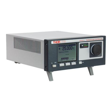
THORLABS
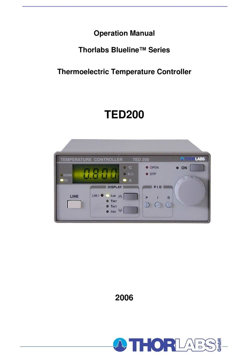
THORLABS TED4015 User manual

THORLABS
THORLABS TCLDM9 User manual

THORLABS
THORLABS TC200 User manual

THORLABS
THORLABS TED200C User manual

THORLABS
THORLABS TC300 User manual

THORLABS
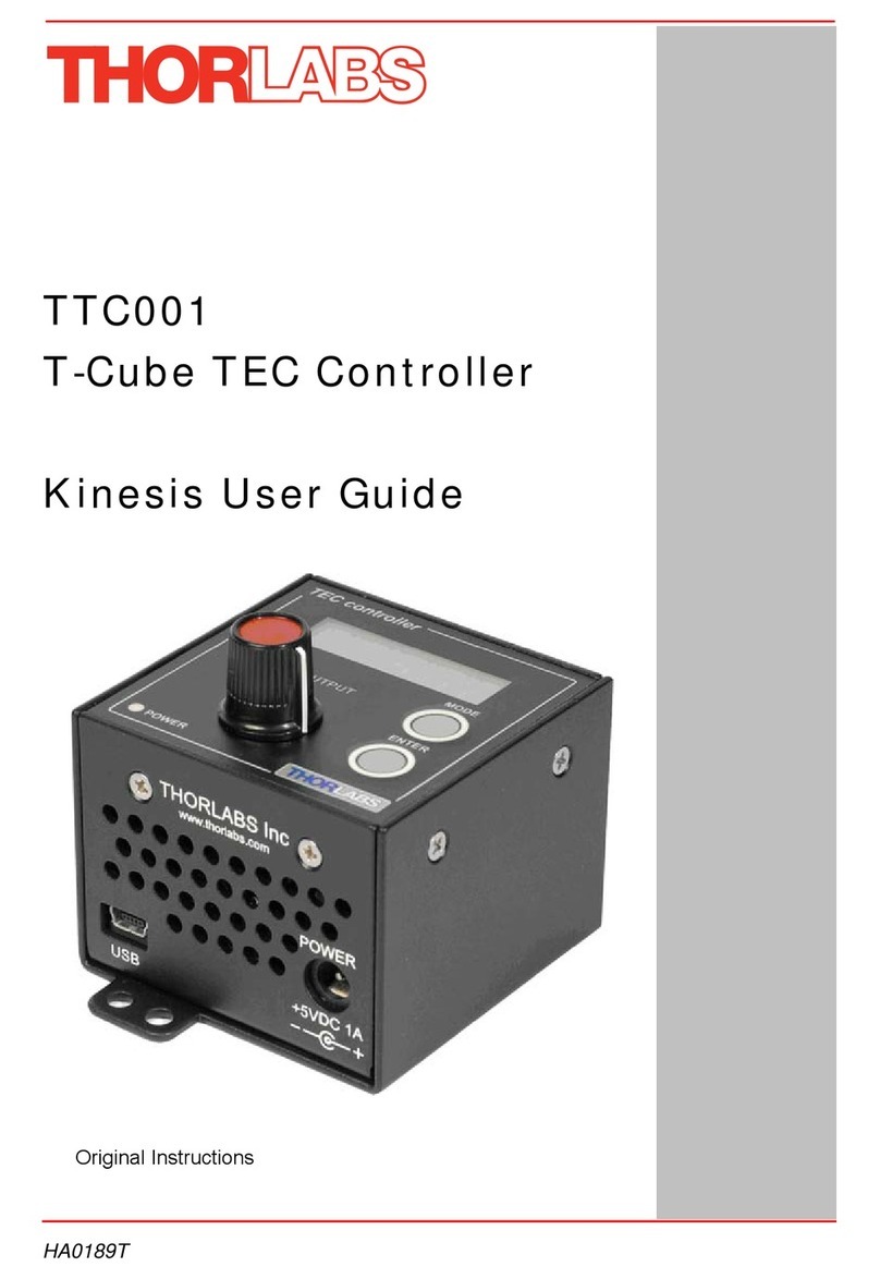
THORLABS T-Cube TTC001 User manual

THORLABS
THORLABS TED350 User manual

THORLABS
THORLABS ITC8000 User manual
THORLABS
THORLABS MTD415T User manual
THORLABS
THORLABS TXP Series User manual