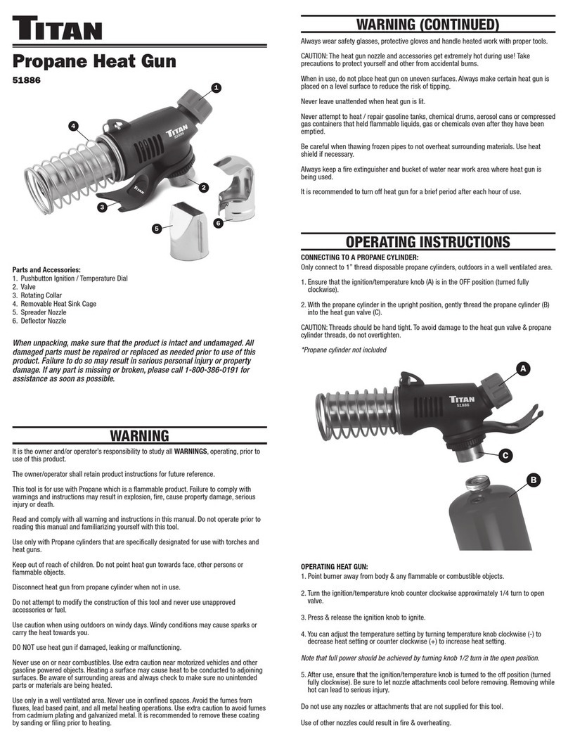
Titan TM45FG User manual

OPERATION MANUAL
TM45FG
TITAN MACHINERY CO., LTD.
www. Titanmachine y.com.cn

1. In order to safety operate the machine please read the
instruction manual seriously especially the “ Safety Items ”
before installation and operation otherwise running machine is
not allowed.
2. The machine was manufacturered according to the following
standards:
EN13128-2001:《Safety of machines-Milling
machines(including boring machine)》;
EN12717-2001 《 Safety of machines tools-drilling
machine》;
EN60204-1:2006《Safety of machinery-Electrical equipment
of machines –Part1:General requirements》;
3. For anything else please contact us according to the following
informations at the proper time:

ENVIRONMENTAL PROTECTION NOTICE
Following instructions should be abided when machine have
to be scrapped finally:
1、 The poisonous, harmful article or un-degradated waste
materials and other waste electric components which can
not be re-used should be sent to the designated place to
deal with.
2、 The waste liquids like lubrication oil and coolant which
cannot be re-used should be sent to the designated place to
deal with.
3、 We suggest the workshop to equip with drawing device to
exhaust the poisonous, harmful gases created during
machining。

1. SAFETY ITEMS
1.BASIC SAFETY ITEMS
▲ DANGER!
1.1The electric system should have good earth, the yellow and
green leads should not less than 2.5mm
2
。 The required
earth line which import power supply general earth terminal are
muti-ply yellow/green soft wires which≥4mm
2
,and connect to
copper bar. Machine and building should have reliable earth
system.
1.2 The un-trained person should not operate the machine
otherwise will be dangerous.
1.3 Don’t touch the place marked “lightning” when machine
electrified otherwise will get an electric shock.
1.4 Remove and re-equip the safety guard without authorization
is forbidden.
1.5 Remember the position of emergency stop button so that you
can stop the machine in any case.
1.6 Do not open the safety guard when machine running.

▲ WARNING!
1.7 Do not touch the rotating workpiece and tools.
1.8 Check moving parts of machine and make sure the safety
guard is reliable before power connection.
▲ NOTE!
1.9 Un-specific person cannot open the electric box to repair the
electrical equipment.
1.10 We suggest use the coolant accorded with environment
protection and assigned lubricant.
2. SAFETY ITEMS WHEN OPERATING
▲ DANGER!
2.1 The installed work piece and tool should be firmed and reliable,
prevent the work piece from interference with other parts of
machine otherwise not to run the machine.
2.2 Make sure no obstacles in the running range before starting
machine otherwise not to run the machine.
2.3 Close the safety guard to prevent injury from the chips and
spattering coolant when machine running.
2.4 Stop all other operation when changing tool or work piece.
2.5 Check after installing work piece make sure the firm clamping
then start milling or drilling.

2.6 Do not use the wet hand to touch the electric components
otherwise the created short-circuit will cause personal injury.
2.7 Turn the feed switch button to the (OFF),and turn the
feed control button to(0) when tapping。
2.8 Adjust flow of coolant under the circumstance of stopping.
2.9 Do not wear gloves when operating machine.
2.10 Machine put on the flat and firmed foundation which should
be ready a month ago and then level the machine.
2.11 When lifting the machine, make sure the lifting device is
reliable; the load of lifting equipment should bigger than the
machine gross weight and the defected lifting tools are
forbidden; lock all handles before lifting and put soft things
between ropes and machine to avoid of damaging the machine
and paintings.
2.12 Fix the foundation bolt to prevent machine from inclining.
2.13 Make sure machine in good status before operation.
2.14 Remove the chips timely when heavy cutting because the hot
chips will catch fire.
2.15 Do not touch the coolant with naked hand. To wear the
special gloves avoid of skin allergy.

▲ NOTE!
2.16 Timely lubricate the machine according to the instruction
manual.
2.17Suggest not running the machine during the thunder weather.
2.18 If you want to leave for a while shut off the power supply
switch on the operation panel and the main power supply switch
after finishing procession.
3. MAINTENANCE SAFETY ITEMS
▲ DANGER!
3.1 Shut off the general power supply before performing any
maintenance and do not let anyone else to start the machine.
3.2 Shut off the power supply a period of time and check with
multimeter to make sure no more dangerous voltage then start
to repair.
3.3 Do not remove the safety device of machine (such as limit
switch, dog etc) otherwise safety accident will be caused.
3.4 Make sue all removed parts recover then running machine.
▲ WARNING!
3.5 Electric equipment maintenance should be performed by the
qualified electric engineer.
3.6 Do not remove or change the mutual- lock structure like limit
switch , dog and etc.

▲ NOTE!
3.7 The changed electric components should be same with the
original one.
3.8 Put the removed parts far away from the machine to keep
safety.
4、SAFETYGUARD POINTS FOR ATTENTION
▲ DANGER!
4.1 Stop machine when cleaning。
▲ WRNING!
4.2 Change the easy damaged parts according to the manual.
▲ NOTE!
4.3 Clean the machine after working to keep working place clean.
2. USAGE AND FEATURES
The machine may perform drilling, enlarging, tapping,
milling and surface machining to the small and medium sized
parts with good rigidity and high accuracy. It is also possess
auto-tapping function. Machine have 4 spindle auto feed for
selection according to the different materials and different
procession size. It is widely used in factory, school , family and
etc.

1. MAIN STRUCTURE AND FEATURES
The machine is consist of base, column, cross table, spindle
box, motor and etc. The spindle can get 6 to 12 speeds by the
motor through gear transmission of each axis. Strong structure of
spindle may install many kinds of tools to process and the
spindle sleeve is equipped with lock device which make the
positioning more reliable. Also the super strong column make
machine more rigidity.
The machine is applied with 3 phase motor and equipped
with complete coolant system.
The machine is applied with gear transmission and gears are
more durable after special treating. When need to adjust speed,
two groups of sliding gear adjusted by the speed handle, easy
operation and flexible.
2. MACHINE TRANSPORTION AND INSTALLATION

DIA.1
Dia.1
1、TRANSPORTION
Machine sends to the customer with solid packing. Please pay
attention to the marks (especially the rope position and center

position), do not place upside down, incline, put crosswise and
shock the machine when lifting.
Because the bottom area of packing is small and machine is
higher we suggest use crane or forklift to transport.
NOTE:MACHINE GROSS WEIGHT 350KG
Please use forklift before removing packing (as Dia.1) .Open
the packing and check the accessories then put the machine on
the installation foundation.
When using hoisting equipment after removing the packing,
the hoisting capacity of a crane should be bigger than the
machine gross weight. Lock all handles before lifting and put soft
things between ropes and machine avoid of damaging the
machine parts and paintings.

Use the firm ropes to lift machine and keep balance when
moving(as Dia.2).
图2
Dia.2

The smallest site area of this machine is the circle area which
table moves one circle around the column. Please consider the
work piece, tool box, accessories area, operation space,
maintaenance space (as Dia. 4) when machine taking its’ place.
Too close to the wall , other machines or objects is un-easy and
un-safe.。
Dia. 4
Machine far away from the sunshine and keep the
environment dry and clean.

5.MAIN TECHNICAL PARAMETER
Model 45
Drilling
capacity
cast iron 45mm
mild steel 32mm
Face mill capacity 80mm
End mill capacity 32mm
Working table size 800mm×240mm
Working table cross travel
175mm
Working table longitudinal
travel
560mm
T-Slot size 14mm
Head tilt left right 90°
Spindle taper (option) MT3 or MT4 R8
Max distance spindle to table
450mm 440mm
Spindle stroke 120mm
Spindle speed(rpm)
50HZ 95 190 325 465 910 1600
60HZ 114 228 390 558 1100 1920
Overall dimension
1090mm
×1120mmm×785mm
Packing dimension 850mm×760mm×1150mm
NW/GW Weight 300/350Kg

MACHINE LUBRICATION
The transmission box of this machine is applied with sealed
type rolling bearing which no need to lubricate. Bearings
installed on the cross table need to be manually lubricated as
Dia.5 showed follow:
Dia.5
(1)Spindle transmission parts need to be lubricated twice a
year with high grade lubricant.
(2)Auto feed transmission parts lubricated with high grade

lubricant. There is an oil cup on the worm gear, oiling twice every
shift.
(3)To make the machine operating more flexible ,oil film
should be formed on the spindle sleeve and the surface of column
to prevent rust and stop dust.
(4)The return spring should be lubricated once a year.
(5)Column, cross table and ball screw should be oiling every
operation.
(6)Lubricate oil should be added to the oil marks of gear box
before operating and oil in gear box should be changed once a
year.
MACHINE ADJUSTMENT
(1)Up and down adjustment of spindle box. To loose the lock
handle on the right side of vertical slide and turn the handle on the
left side of knee may realize up and down movement of spindle box
along the column. When it reaches the working height tightly lock
the right side handle.
(2)The worm gear in the spindle auto feed structure and the
clutch housing have been adjusted to the best position when
machine dispatched. Elasticity of spring would be changed after a
period of time using, adjust the spring pressure properly at the
time.

(3)Adjustment of cross table backlash and wear compensation
a.The wedge installed on the cross slide to adjust backlash of
table and perform wear compensation.
b. When backlash is big, clock wise turning the bolt on the cross
slide and when backlash is small adjust a little on the contrary.。
c. The screw for adjusting wedge make the table lightly.
MACHINE OPERATION
(1)DRILLING
a. To pull the feed operation handle when drilling, tapping,
reaming may rapidly move down the spindle. Draw the handle
to the right auto feed can be realized. Three feed capacity were
designed for customer’s selection. When need to control drilling
depth, loose the fixed handle of dial first , adjust dial to the
required depth then tighten up the fix handle you may start
drilling. When drilling to the controlled depth the operation
handle will return back automatically and the spindle will return
to the original position also.
b. When need manual feed, draw the feed control handle to
the left and tighten up the limit handle to limit right drawing of
the feed handle.
c. Machine can perform tapping according to the customer’s
request.

When need auto tapping, turn the knob to the tapping position,
rotate the feed handle to the required depth, adjust to the
proper speed then start tapping. When the tap reaches the
controlled depth, the spindle will return back to the original
position.
NOTE : When troubles happens in tapping, press the
emergency
stop button to stop the spindle rotation.
After finishing tapping turn the feed switch to the normal
position.
2.MILLING
a. To turn the feed switch and feed capacity knob to(OFF)
when milling, tighten up the limit handle. When setting the tool,
turn the manual feed handwheel dial to“0” then adjust handwheel
to the required depth.
b. Tighten up the lock handle of spindle sleeve when milling
to assure the milling accuracy and roughness.
c. After finishing milling, loose the lock handle of spindle
sleeve first then counter clockwise rotate the manual feed handle
to return to the original position. Your may also loose the limit

handle, draw the operation handle to the left and return to the
original position by the worm shaped spring.
(4)When performing cross milling, rotate the two screws
on the right side of cross slide to lock longitudinal movement, as
Dia.8.
(5)When performing longitudinal milling, rotate the two
screws in front of cross slide to lock cross movement, as Dia.9.
(6)Adjust two travel dogs in front to table to control the
milling travel.

TOOL CHANGING
(1)The tail of twist drill insert into the flat slot in the spindle
hole, check the drill installation then start operation.
When removing the twist drill, put the small end of tool back
wedge to the top of tail in the spindle tool back hole from tool
back hole lies in the right side of spindle sleeve, hole the drill with
left hand then knock the big end of tool back wedge lightly, tool
will be taken out. Do not drop the tool on the table or work
piece.
(2)Installation of reamer and boring tool are same as above.
(3)When installing the drill less thanφ13,install he drill
chuck onto the spindle hole first, steps are same as above. Then
loose drill chuck, put the drill shank into the drill chuck and
tighten up. Make sure the fix installation then start drilling.
(4)Mills installation and removement
a. Install the mill or mandrel and draw bar onto the spindle,
tighten up the draw bar and mill or mandrel. Note not too tight.
b. When removing the mill, use the spanner to loose draw
bar about two circles, knock it lightly with hammer then hold
the tool with one hand and take away the draw bar with
another hand.
Table of contents
Other Titan Power Tools manuals

Titan
Titan TTB280DRH Installation manual

Titan
Titan TTB285JSW User manual

Titan
Titan SF800XPL Installation manual

Titan
Titan TTB883ROU User manual

Titan
Titan TS005V2 User manual

Titan
Titan TTK587GD0 Installation manual

Titan
Titan LX-70 User manual

Titan
Titan PR 33 User manual

Titan
Titan CAPSpray 0524000 User manual

Titan
Titan TT5MTP26-2 User manual

Titan
Titan SF1500XP Installation manual

Titan
Titan EHS User manual

Titan
Titan TTI866JSW User manual

Titan
Titan TTB935HTG User manual
Titan
Titan Pro V55 User manual

Titan
Titan SF1022 Installation manual

Titan
Titan TTB773HTG User manual

Titan
Titan TTB591ROU Installation manual
Titan
Titan TTB924DBT User manual

Titan
Titan 51886 User manual