TOORX BRX Compact MultiFit User manual

Ed : 02/17
INSTRUCTION
Rev: 0000

PRODUCT OVERVIEW
Meter
Upright
Left Pedal
Left Front
Cover
End Cap
Front
Stabilize
r
Left
Chain Cover
Handlebar
Pu
l
se
Sensor
Adjustment nob
Seat
End Cap
Transport Wheel
Rear
Stabilizer
THEFOLLOWINGTOOLS ARE INCLUDED
Wrench:
FOR ASSEMBLY Allen Wrench (5mm) w/ Screwdriver:
Back Support
Back Cushion
Back Frame
Top Cover
Adjustment nob

HARDWARE IDENTIFICATION CHART
Figure No.
Description Qty
D5
D8
Carriage Bolt (M8*1.25*60mm)
Carriage Bolt (M8*1.2548 mm)
4
2
D7 Bolt, Button Head (M8* 40 mm) 4
D17 Screw, Round Head (M6 x 1 x 12mm) 1
D22 Acorn Nut (M8) 4
D23 Arc Washer (M8) 4
D24 Washer (M8) 6
D25
Nut M8 2
D1 Adjustment Knob 2
D2 Pull Pin 1

A
AS
SS
SE
EM
MB
BL
LY
Y
I
IN
NS
ST
TR
RU
UC
CT
TI
IO
ON
N
Place all parts from the box in a cleared area and position them on the floor in front of you.
Remove all packing materials from your area and place them back into the box. Do not
dispose of the packing materials until assembly is completed. Read each step carefully
before beginning.
STEP 1: Unfold the Rear Frame (A2) away from the Main Frame (A1). Locking the frame
assembly in unfold position by inserting the Pull PIN (D2) into the hole in the Rear Frame
(A2). Forward pushing Upright (A3) to the maximum angle and stepping down to fixed
the Lever Cover (B6).
STEP2: Attach the Rear Stabilizer (A10), the one with Transport Wheels (B19), to the Rear
Frame (A2) with the wheels facing backward. Secure with Carriage Bolts (M8*60mm)
(D5), Acorn Nuts (M8) (D22), and Arc Washers (M8) (D23).
STEP 3: Attach the Front Stabilizer (A5) to the Main Frame (A1) with Carriage Bolts (M8*60mm)
(D5), Acorn Nuts (M8) (D22), and Arc Washers (M8) (D23).

A
AS
SS
SE
EM
MB
BL
LY
Y
I
IN
NS
ST
TR
RU
UC
CT
TI
IO
ON
N
STEP 4: Attach the Seat (B24) to the Seat Post (A6) with Nylock Nuts (M8) (D25) and Washer
(M8) (D38). Insert the Seat Post (A6) into the Main Frame (A1) and secure with the
Adjustment Knob (D1).
NOTE:
1. Make sure that the pin on the Adjustment Knob (D1) is inserted into one of the holes in Seat
Post (A6).
2. The Adjustment Knob (D1) should be screwed in tight to make the Seat Post (A6) fit securely
in the Main Frame (A1).
STEP 5: Attach the Back Frame (A7) and Seat Post (A6) by using Carriage Bolt (M8*1.25*48mm)
(D8) and Washer (M8) (D24).
STEP 6: Attach the Back Cushion (B25) and Back Support (A9) by using Button Head Bolt
(M8*40) (D7) and Washer (M8) (D24).

A
AS
SS
SE
EM
MB
BL
LY
Y
I
IN
NS
ST
TR
RU
UC
CT
TI
IO
ON
N
STEP 7: Insert the
Handlebar (A15)
onto the Upright (A3) and tight it by usingAdjustment Knob
(D1). Attach the
Handlebar (A15) to the Upright (A3) by using the Bolt, Button Head M8*40
(D7).
STEP 8: Connecting Meter Transmission Wire (C2) into the
Sensor Bracket (C13)
.

STEP9: Tighten the Left
Strap (B29) and Right Strap (B30) to the Left Pedal (B27) and Right Pedal
(B28).
Lock and tight the Left Pedal (B27) and Right Pedal (B28) on the Left Crank (C5)
and Right Crank (C6) by using the Wrench.
FUNCTION INSPECTION:
Visually inspect the Bike to verify that assembly is as shown in the above illustration.
Check the function of the Bike by turning the c rank s lowly through one complete revolution to
verify that the drive train functions properly. Adjust the Adjustment Knob (33) and verify that it
functions properly and the resistance changes.

OPERATIONAL INSTRUCITONS
USING THE FITNESS METER
POWER ON: Pedal movement or press the button.
POWER OFF: Automatically shuts off after four minutes of inactivity.
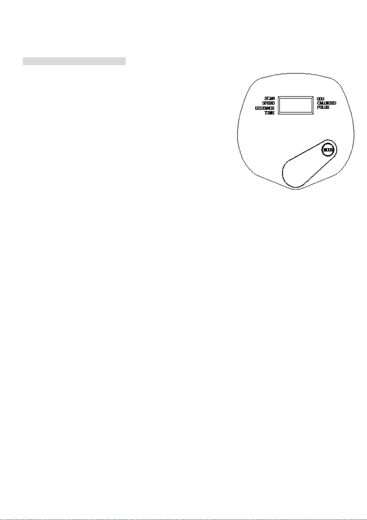
MODE BUTTON:
Press to select display functions, including SCAN, TIME, SPEED,
DISTANCE,
CALORIES, ODOMETER, and PULSE.
Press and hold for two seconds to reset all functions to zero, except
ODOMETER.
FUNCTIONS:
SCAN: Automatically scans each function of TIME, SPEED, DISTANCE, CALORIES,
ODOMETER, and PULSE in sequence, display changes every six seconds. Press and release the button
until “SCAN” appears on the display.
TIME: Displays the time from one second up to 99:59 minutes.
SPEED: Displays the current speed from zero to 999.99 KM.
DISTANCE: Displays the distance from zero to 99.99 KM.
CALORIES: Displays the calories burned from zero to 999.9 Kcal. The calorie readout is an estimate for an
average user. It should be used only as a comparison between workouts on this unit.
ODOMETER: Displays the total accumulated distance you have traveled from zero to 999.9 KM. The total
accumulated distance is retained when the meter is turned off.
PULSE: Displays your pulse rate in beats per minute. To display pulse, select the PULSE mode and grasp
the pulse sensors on the handlebar, one in each hand. The heart icon will begin flashing when the
FITNESS METER senses your pulse. Your pulse will be displayed approximately five (5) seconds after the
heart icon is displayed. If the heart icon does not appear, relax your grip or change your grip on the pulse
sensors.
NOTE: 1. The meter will shut off automatically after four minutes of inactivity. All function values will be
kept. Press the button and hold it down for two seconds to reset all functions to zero, except ODOMETER.
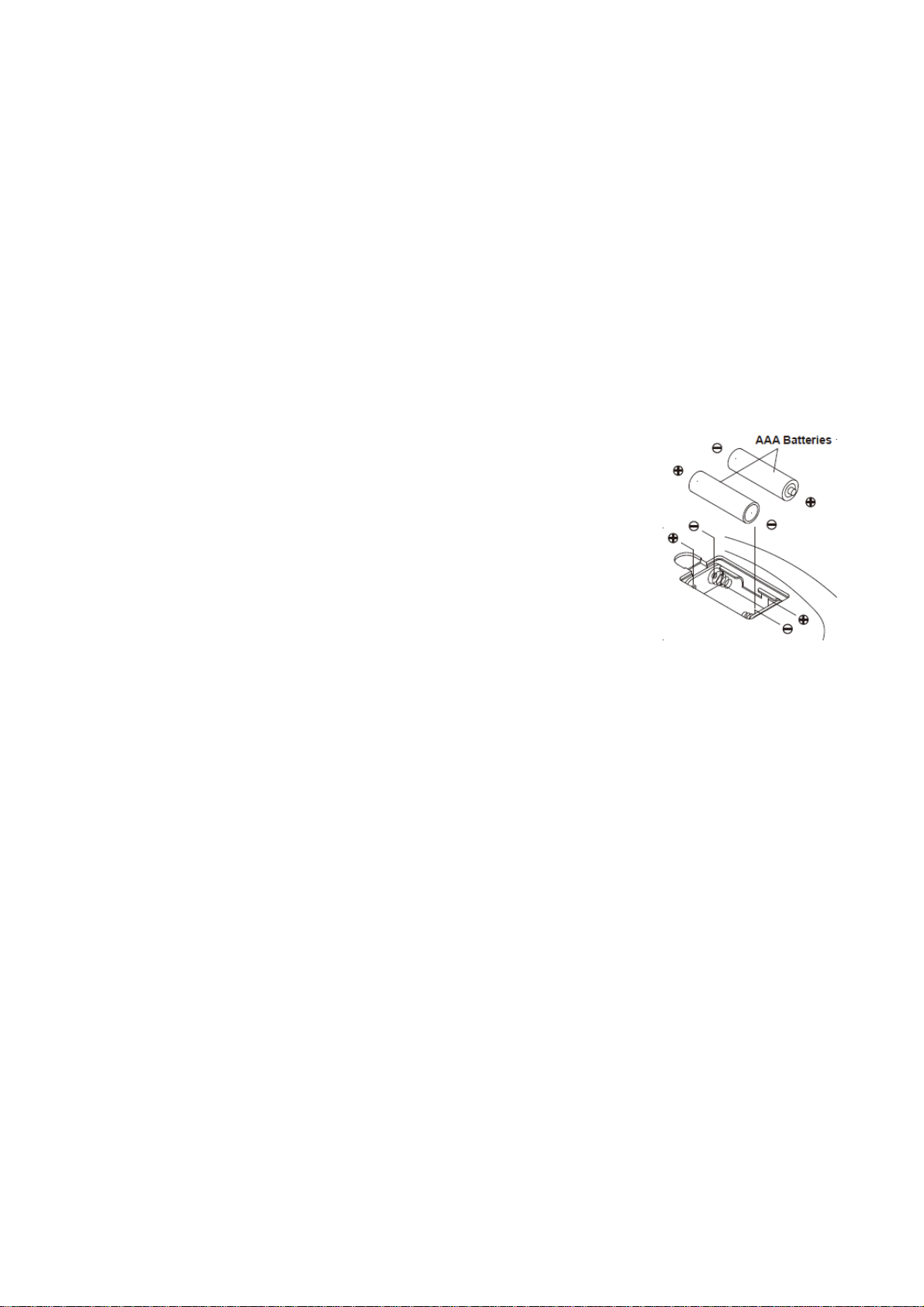
2.The ODOMETER will be reset to zero after batteries are removed for battery replacement or storage of
the unit.

HOW TO INSTALL AND REPLACE BATTERIES
1.
Open the Battery Door on the back of the meter.
2.
The meter operates with two AAA batteries, the batteries are not included. Refer to the illustration to
install or replace the batteries.
NOTE:
1. Do not mix a new battery with an old battery.
2. Use the same type of battery. Do not mix an alkaline battery with another type of battery.
3. Rechargeable batteries are not recommended.
4. Ultimate disposal of battery should be handled according to all state laws and regulations.
5. Do not dispose of batteries in fire.

LOAD ADJUSTMENT
To increase the load, turn the Adjustment Knob (B32) clockwise.
To decrease the load, turn the Adjustment Knob (B32) counterclockwise.
There are eight levels for the load adjustment.
SEAT ADJUSTMENT
Proper seat adjustment is important.
1.
Turn the Adjustment Knob (D1) to loosen, then pull the Adjustment
Knob (D1) to release the pin. Slide the Seat Post (A6) until the Seat
(B24) is at the proper height. Release the Adjustment Knob (D1)
making sure the pin catches in one of the holes of the Seat Post
(A6) and tighten the Adjustment Knob (D1)
2.
Sit on the seat and place your feet on the pedals. You
should be able to move through a complete pedal stroke
without locking your knees or shifting your hips on the seat.
The seat is too close to the pedals if you have more than as
light bend in your knees at the bottom of the pedal stroke.
The seat is too far from the pedals if you have to completely
straighten your knees at the bottom of the pedal stroke.
Refer to the illustration.
CAUTION:
1. Do not attempt to adjust the seat while you are on the
BIKE.
2. Always tighten the Adjustment Knob (D1) after adjusting
the seat to a new position.

OPER
A
TIONALINSTRUCTIONS
STORAGE
• To store the BIKE, simply keep it in a clean dry place.
• To avoid damage to the electronics, remove the batteries before storing the BIKE for one year or more.
• To move the BIKE, hold the HANDLEBAR and tilt the BIKE onto the Wheels of the Stabilizer at the front.
• Follow the illustrated process below to fold the BIKE.
•Remove the Pull Pin (D2), fold the Rear Frame (A2) forward. Insert the Pull Pin (D2) back into the Rear
Frame (A2) after folding.
•Remove the Pull Pin (D2) from the Rear Frame (A2).Fold the Rear Frame (A2) close to the Main Frame
(A1) and lock it in folded position with the Pull Pin (D2).
NOTE: Make sure the Pull Pin (D2) goes through the holes on both sides of the Rear Frame (A2) and
the tube on the Main Frame (A1).
The safety and integrity designed into the
BIKE
can only be maintained when the
BIKE
is regularly
examined for damage and wear. Special attention should be given to the following:
1.
Adjust the Adjustment Knob (B32) and verify that it functions properly and the resistance changes.
2.
Use a wrench to verify that the pedals are tightened securely. If tightening is required, remember that
the left pedal has left hand threads and is tightened by turning counterclockwise.
3.
Verifythatallnutsandboltsarepresentandproperlytightened.Replacemissingnutsandbolts. Tighten loose
nuts and bolts.
4.
It is the sole responsibility of the user/ owner to ensure that regular maintenance is performed.
5.
Worn or damaged components shall be replaced immediately or the BIKE removed from service until

OPER
A
TIONALINSTRUCTIONS
repair is made.
6.
Keep your BIKE clean by wiping it off with an absorbent cloth after use.
UPRIGHT ADJUSTMENT
Refer to the illustrations below. The angle of the Meter (C1) can be set to different angles from
Position 1 to Position 5. Lift the Lever cover (B6) up using your right foots, adjust the Upright
(A3)/
Meter (C1) to desired position. Then press the Lever cover (B6) down to lock the
Upright (A3)/
Meter (C1) in position.

T
OCO
N
T
ACTCUS
T
OMERSERVICE
17

T
OCO
N
T
ACTCUS
T
OMERSERVICE
18
PARTS LIST
A. Welding Parts
No.
Description
QTY
A1 Main Frame 1
A2 Rear Frame 1
A5 Front Stabilizer 1
A6 Seat Support 1
A7 Back Frame 1
A9 Back Support 1
A10 Rear Stabilizer 1
A11 Lever 1
A12 Magnetic Bracket 1
A13 Shaft 1
A15 Handlebar 1
B. Plastic Parts
No.
Description
QTY
B1 Left Chain Cover 1
B2 Right Chain Cover 1
B3 Top Cover 1
B4 Left Front Cover 1
B5 Right Front Cover 1
B6 Lever cover 1
B7 Hollow Cap 1
B12 Sensor Bracket 1
B13 Bushing 1
B14 Plastic Bushing 6
B15 Oval Plug (20mm*40mm) 2
B16 Plastic Washer Φ8.5*Φ20*2.0T 2
B17 Rubber Cushion 1
B18 Leveling Cap 2
B19 Wheel 2
B20 Inner Plug 2
B21 Tube Bushing S30*30 1
B22 Tube Bushing S15*30 4
B23 Bumper 1
B24 Seat 1
B25 Back Cushion 1

T
OCO
N
T
ACTCUS
T
OMERSERVICE
19
B26 Foam Grip 400 2
B27 Left Pedal 1
B28 Right Pedal 1
B29 Left strap 1
B30 Right strap 1
B31 Crank Cap 2
B32 Adjustment Knob 1
B33 Adjustment Knob Bracket 1
B35 Plastic WasherΦ10.2*Φ14 2
B37 Stopper 1
B38 Endcap 2
B39 Bearing Housing 2
B40 Hand grip 2
B44 Plug 1
C. Electrical parts
No.
Description
QTY
C1 Meter 1
C2 Connection Wire 1
C3 Folding Axis
1
C5 Left Crank 1
C6 Right Crank 1
C7 Flywheel 1
C8 V-Ribbed Belt (230J) 1
C9 V-Ribbed Belt(240J) 1
C10 Pulley w/ Shaft 1
C11 Pulley Shaft 1
C12 Pulley 1
C13 Sensor 1
C14 Ball Bearing (6000ZZ) 2
C15 Ball Bearing (6200ZZ) 1
C16 Ball Bearing (6003ZZ) 2
C17 Idler Shaft 1
C18 Magnet 6
C19 Idler Shaft 1
C20 Magnet 1
C21 Hand Pulse 4
C22
Hand pulse Line
1

T
OCO
N
T
ACTCUS
T
OMERSERVICE
20
D. Hardware
No.
Description
QTY
D1 Adjustment Knob 2
D2 Ball Pin 1
D4 Allen Wrench 1
D5 Carriage Bolt M8*60 4
D6 Hex Head Bolt M6*45 2
D7 Bolt, Button Head M8*40 4
D8 Carriage Bolt M8*48 2
D9 Bolt, Button Head M8*75 1
D10 Bolt, Button Head M8*20 2
D11 Eye Bolt M6 2
D12 Hex Head Bolt M8X55 2
D13 Hex Head Round Bolt M8X68 1
D15 Screw, Round Head ST4.2*16 9
D16 Bolt, Round Head M5X20 4
D17 Bolt, Round Head (M6*12mm) 10
D19 Wave Washer S10 1
D20 Screw, Round Head ST4.2*25 2
D21 Flange Nu M10*1.25 2
D22 Acorn Nut M8 4
D23 Arc Washer M8 4
D24 Washer M8 8
D25 Nylock Nut M8 7
D26 Nut M10 2
D27 U-Shape Bracket 2
D28 Nylock Nut M6 2
D29 C Ring Φ17.0 6
D30 C Ring Φ10 2
D31 Wave Washer S17 1
D32 Spring Washer M8 3
D33 Large Washer(ø8.2*ø25*2mm) 2
D34 Nut M10 1
D35 Carriage Bolt M4X10 1
D36 Nylock Nut M10 1
D37 Nylock Nut M8 2
D38 Washer M8 3

T
OCO
N
T
ACTCUS
T
OMERSERVICE
21
D39 Nylock Nut M6 2
D41 Bearing Housing Cover 2
D42 Spring 1
D43 Bolt M5X55 1
D44 Washer (M5) 1
D47 Wrench 13-15 1
D49 Screw, Round Head ST4.0*20 2

GARLANDO SPA
Via Regione Piemonte, 32 - Zona Industriale D1
15068 - Pozzolo Formigaro (AL) - Italy
www.toorx.it - info@toorx.it
Table of contents
Other TOORX Exercise Bike manuals

TOORX
TOORX BRX85 User manual

TOORX
TOORX BRXR 90 User manual

TOORX
TOORX SRX60 EVO User manual

TOORX
TOORX BRX 300 User manual

TOORX
TOORX BRX Compact User manual

TOORX
TOORX BRX COMFORT User manual

TOORX
TOORX BRX 100 User manual

TOORX
TOORX SRX40S User manual

TOORX
TOORX BRX AIR300 User manual

TOORX
TOORX ERX 65 User manual