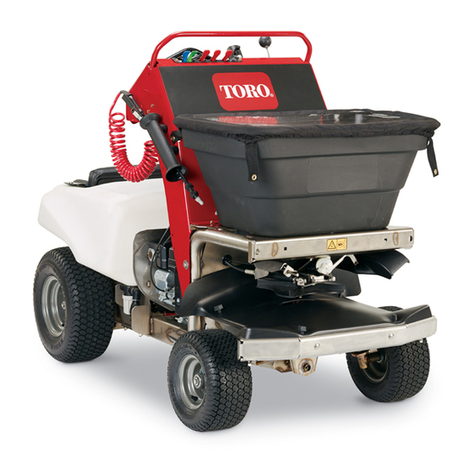
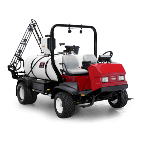
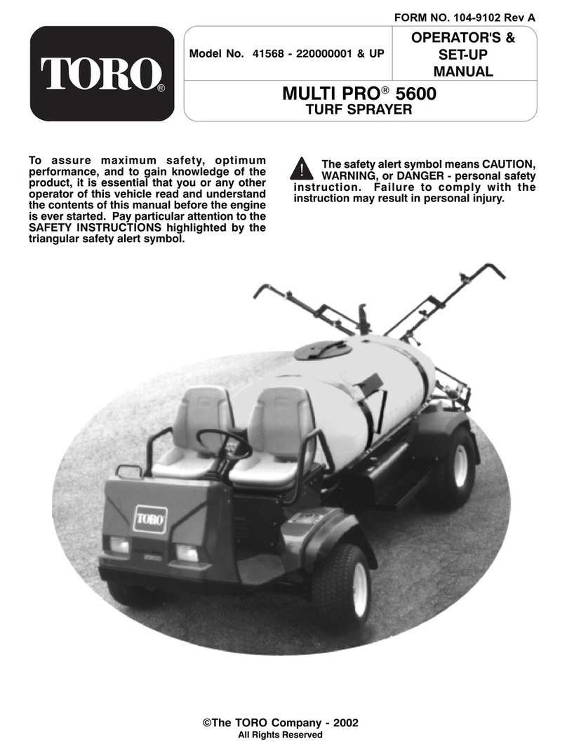
Toro MultiPro 1750 User manual

FormNo.3422-212RevA
MultiPro®1750TurfSprayer
ModelNo.41188—SerialNo.401381101andUp
Registeratwww.Toro.com.
OriginalInstructions(EN)*3422-212*A

ThisproductcomplieswithallrelevantEuropean
directives;fordetails,pleaseseetheseparateproduct
specicDeclarationofConformity(DOC)sheet.
ItisaviolationofCaliforniaPublicResourceCode
Section4442or4443touseoroperatetheengineon
anyforest-covered,brush-covered,orgrass-covered
landunlesstheengineisequippedwithaspark
arrester,asdenedinSection4442,maintainedin
effectiveworkingorderortheengineisconstructed,
equipped,andmaintainedforthepreventionofre.
Theenclosedengineowner'smanualissupplied
forinformationregardingtheUSEnvironmental
ProtectionAgency(EPA)andtheCaliforniaEmission
ControlRegulationofemissionsystems,maintenance,
andwarranty.Replacementsmaybeorderedthrough
theenginemanufacturer.
WARNING
CALIFORNIA
Proposition65Warning
Theengineexhaustfromthisproduct
containschemicalsknowntotheStateof
Californiatocausecancer,birthdefects,
orotherreproductiveharm.
Batteryposts,terminals,andrelated
accessoriescontainleadandlead
compounds,chemicalsknownto
theStateofCaliforniatocause
cancerandreproductiveharm.Wash
handsafterhandling.
Useofthisproductmaycauseexposure
tochemicalsknowntotheStateof
Californiatocausecancer,birthdefects,
orotherreproductiveharm.
Introduction
Thismachineisadedicatedturfsprayapplication
machineandisintendedtobeusedbyprofessional,
hiredoperatorsincommercialapplications.Itis
designedprimarilyforsprayingonwell-maintained
lawnsinparks,golfcourses,sportselds,andon
commercialgrounds.
Itisintendedforoff-roaduseandnotforextensive
drivingonpublicroads.
Readthisinformationcarefullytolearnhowtooperate
andmaintainyourproductproperlyandtoavoid
injuryandproductdamage.Youareresponsiblefor
operatingtheproductproperlyandsafely.
YoumaycontactT orodirectlyatwww.T oro.com
forproductsafetyandoperationtrainingmaterials,
accessoryinformation,helpndingadealer,orto
registeryourproduct.
Wheneveryouneedservice,genuineT oroparts,or
additionalinformation,contactanauthorizedToro
distributororT oroCustomerServiceandhavethe
modelandserialnumbersofyourproductready.
Figure1identiesthelocationofthemodelandserial
numbersontheproduct.Writethenumbersinthe
spaceprovided.
Important:Withyourmobiledevice,youcan
scantheQRcodeontheserialnumberdecal(if
equipped)toaccesswarranty,parts,andother
productinformation.
g237021
Figure1
1.Locationofthemodelandserialnumbers
ModelNo.
SerialNo.
©2018—TheToro®Company
8111LyndaleAvenueSouth
Bloomington,MN554202
Contactusatwww.Toro.com.
PrintedintheUSA
AllRightsReserved

Thismanualidentiespotentialhazardsandhas
safetymessagesidentiedbythesafety-alertsymbol
(Figure2),whichsignalsahazardthatmaycause
seriousinjuryordeathifyoudonotfollowthe
recommendedprecautions.
g000502
Figure2
1.Safety-alertsymbol
Thismanualuses2wordstohighlightinformation.
Importantcallsattentiontospecialmechanical
informationandNoteemphasizesgeneralinformation
worthyofspecialattention.
Contents
Safety.......................................................................4
GeneralSafety...................................................4
SafetyandInstructionalDecals..........................5
Setup......................................................................12
1InstallingtheAnti-SiphonFill
Receptacle....................................................12
2CheckingtheSection-HingeSprings..............13
ProductOverview...................................................14
Controls...........................................................16
Specications..................................................20
Attachments/Accessories.................................20
BeforeOperation.................................................20
BeforeOperationSafety...................................20
PerformingPre-StartingChecks.......................21
PreparingtheMachine......................................22
BreakinginaNewMachine..............................23
PreparingtheSprayer.......................................23
LocatingtheSprayPump..................................30
DuringOperation.................................................31
DuringOperationSafety...................................31
OperatingtheMachine.....................................32
UsingtheDifferentialLock................................33
OperatingtheSprayer......................................33
PositioningtheSpraySections.........................34
SprayingTips....................................................35
UncloggingaNozzle.........................................35
AfterOperation....................................................35
AfterOperationSafety......................................35
CleaningtheSprayer........................................36
Maintenance...........................................................41
MaintenanceSafety..........................................41
RecommendedMaintenanceSchedule(s)...........42
DailyMaintenanceChecklist.............................43
NotationforAreasofConcern...........................44
Pre-MaintenanceProcedures..............................44
RaisingtheSprayer..........................................44
Lubrication..........................................................45
GreasingtheMachine.......................................45
GreasingtheSprayerPump.............................45
GreasingtheSectionHinges............................46
EngineMaintenance...........................................46
EngineSafety...................................................46
CheckingtheAir-IntakeScreen........................46
ServicingtheAirCleaner..................................46
ServicingtheEngineOil....................................47
ChangingtheSparkPlugs................................49
FuelSystemMaintenance...................................50
ReplacingtheFuelFilter...................................50
ServicingtheCarbonCanister..........................50
DrainingtheFuelT ank......................................51
ElectricalSystemMaintenance...........................51
ElectricalSystemSafety...................................51
LocatingtheFuses...........................................51
ServicingtheBattery.........................................51
DriveSystemMaintenance..................................53
InspectingtheWheelsandTires.......................53
AdjustingtheDifferential-LockCable................53
AdjustingtheFrontWheelToe-in......................54
BrakeMaintenance.............................................55
CheckingtheBrakeFluid..................................55
InspectingtheBrakes.......................................55
AdjustingtheParkingBrake..............................55
HydraulicSystemMaintenance...........................56
HydraulicSystemSafety...................................56
HydraulicFluidSpecication.............................56
CheckingtheTransaxle/Hydraulic
Fluid..............................................................56
ChangingTransaxle/HydraulicFluid.................56
ReplacingtheHydraulicFilter..........................57
CheckingtheHydraulicLinesand
Hoses............................................................57
SpraySystemMaintenance.................................58
InspectingtheHoses........................................58
ChangingtheSuctionFilter...............................58
ChangingthePressureFilter............................58
ChangingtheNozzleFilter................................59
InspectingthePump.........................................59
InspectingtheNylonPivotBushings.................60
AdjustingtheBoomstoLevel............................60
Cleaning..............................................................61
CleaningtheFlowMeter...................................61
CleaningtheSprayerValves.............................62
Storage...................................................................71
PreparingtheSprayerSystem..........................71
PerformingtheServiceProcedures..................72
PreparingtheEngineandBattery.....................72
PreparingtheMachine......................................72
Troubleshooting......................................................73
Schematics.............................................................76
3
Safety
Improperuseormaintenancebytheoperatororowner
canresultininjury.T oreducethepotentialforinjury,
complywiththesesafetyinstructionsandalwayspay
attentiontothesafety-alertsymbol(Figure2),which
meansCaution,Warning,orDanger—personalsafety
instruction.Failuretocomplywithinstructionmay
resultinpersonalinjuryordeath.
Thismachinehasbeendesignedinaccordancewith
therequirementsofSAEJ2258.
GeneralSafety
Thisproductiscapableofcausingpersonalinjury.
Alwaysfollowallsafetyinstructionstoavoidserious
personalinjury.
Usingthisproductforpurposesotherthanitsintended
usecouldprovedangeroustoyouandbystanders.
•Readandunderstandthecontentsofthis
Operator’sManualbeforestartingtheengine.
•Useyourfullattentionwhileoperatingthe
machine.Donotengageinanyactivitythat
causesdistractions;otherwise,injuryorproperty
damagemayoccur.
•Useappropriatepersonalprotectiveequipment
(PPE)toguardagainstcontactwithchemicals.
Chemicalsubstancesusedinthesprayersystem
maybehazardousandtoxic.
•Donotputyourhandsorfeetnearmoving
componentsofthemachine.
•Donotoperatethemachinewithoutallguards
andothersafetyprotectivedevicesinplaceand
workingonthemachine.
•Keepclearofanydischargeareaofthesprayer
nozzlesandspraydrift.Keepbystandersandpets
asafedistanceawayfromthemachine.
•Keepchildrenoutoftheoperatingarea.Never
allowchildrentooperatethemachine.
•Stopthemachine,shutofftheengine,andremove
thekeybeforelling,emptying,servicing,or
uncloggingthemachine.
Improperlyusingormaintainingthismachinecan
resultininjury.T oreducethepotentialforinjury,
complywiththesesafetyinstructionsandalwayspay
attentiontothesafety-alertsymbol,whichmeans
Caution,Warning,orDanger—personalsafety
instruction.Failuretocomplywiththeseinstructions
mayresultinpersonalinjuryordeath.
Youcanndadditionalsafetyinformationwhere
neededthroughoutthismanual.
Notalltheattachmentsthatadapttothismachine
arecoveredinthismanual.Refertotheoperator’s
manualprovidedwitheachattachmentforadditional
safetyinstructions.
4

SafetyandInstructionalDecals
Safetydecalsandinstructionsareeasilyvisibletotheoperatorandarelocatednearanyarea
ofpotentialdanger.Replaceanydecalthatisdamagedormissing.
decal106-9206
106-9206
1.Wheeltorquespecications
2.ReadtheOperator'sManual.
decal120-0616
120–0616
1.Warning—readtheOperator’sManual;usefresh,clean
waterforrst-aidwashing.
decal120-0617
120–0617
1.Severinghazardofhand,
pinchingpoint—keep
awayfromactuatedjoints.
2.Crushinghazard—keep
bystandersawayfromthe
machine.
decal120-0622
120–0622
1.Warning—readthe
Operator’sManual.
3.Chemicalburnhazard;
toxicgasinhalation
hazard—wearhandand
skinprotection;weareye
andrespiratoryprotection.
2.Warning—donotenterthe
sprayertank.
decal125-4125
125–4125
1.Turnthethrottle
lock/speedlockon/off
3.Turnthefoammakers
on/off(optional)
2.Sonicboom(optional)
5

decal125-4128
125–4128
1.Raise/lowerleftsection4.Engine—run
2.Raise/lowerrightsection5.Engine—shutoff
3.Engine—start
decal125-4129
125–4129
1.Leftsection3.Rightsection
2.Centersection
decal125-6694
125–6694
1.Tie-downlocation
decal133-5619
133-5619
decal137-4289
137-4289
1.Gearselection5.ToggleheadlightsON/OFF
2.Lockdifferentiallock6.SonicBoom—ON
3.Unlockdifferentiallock7.SonicBoom—OFF
4.Horn8.Rewindhosereel
(optional)
6

decal125-8114
125–8114
1.Ratelockout
locked/unlocked
2.Togglerinsepumpon/off
decal127-3935
127–3935
1.Parkingbrake3.Forinformationonshutting
offtheengine,readthe
Operator’sManual—1)
Pressdownonthebrake
pedal;2)Setthegearto
neutral;3)Engagethe
parkingbrake;4)Release
thebrakepedal;5)Turn
theignitionkeytoSTOP
position;6)Removethe
keyfromtheignition.
2.Forinformationonstarting
theengine,readthe
Operator’sManual—1)
Engagetheparkingbrake;
2)Insertthekeyintothe
ignition;3)Turnthekeyto
theenginerunposition.
4.Entanglementhazard,
belt—keepawayfrom
movingparts;keepall
guardsandshieldsin
place.
7

decal127-3937
127–3937
1.Warning—donotstep.3.Entanglementhazard,
belt—keepawayfrom
movingparts;keepall
guardsandshieldsin
place.
2.Warning—keepawayfrom
hotsurfaces.
decal127-3939
127–3939
1.Warning—readthe
Operator’sManual;always
wearaseatbeltwhen
operatingthemachine;do
nottipthemachine.
3.Cutting/dismemberment
hazard—keeparmsand
legsinsidethemachineat
alltimes.
2.Fallinghazard—donot
carrypassengersonthe
sprayertank.
4.Warning—donotdrill,
weld,oraltertheROPS
system.
8

decal127-3942
127–3942
1.ReadtheOperator’s
Manualforinformationon
fuses.
6.7.5A
2.10A—Ignition7.7.5A
3.15A—Sprayersection8.2A—TEC
4.15A—Headlights9.30A—Rinsetank
5.7.5A
decal127-6976
127-6976
1.Decrease2.Increase
decal127-6979
127-6979
1.Pump-returnow3.Agitationow
2.Flow
decal127-6981
127-6981
1.Bypass-returnow3.Sectionspray
2.Flow
decal127-6982
127-6982
1.Bypass-returnow2.Sectionspray
decal127-6984
127-6984
1.Flow2.Tank-returnow
9

decal130-8293
130-8293
1.Sprayeroff5.Increasespeed
2.Sprayeron6.Decreasespeed
3.Engineon7.Agitationon
4.Engineoff8.Agitationoff
decal133-0382
133-0382
1.ReadtheOperator'sManualformoreinformationaboutmaintenance.
10

decal127-3941
127–3941
1.Warning—donotoperatethemachinewithoutpropertraining;
readtheOperator’sManual.
4.Electricalshockhazard,overheadpowerlines—checkthe
areaforoverheadpowerlinesbeforeoperatingthemachine
inthearea.
2.Warning—keepbystandersawaywhenoperatingthe
machine.
5.Warning—Engagetheparkingbrake,shutofftheengine,and
removethekeyfromtheignitionbeforeleavingthemachine.
3.Warning—keepawayfrommovingparts;keepallguardsand
shieldsinplace.
6.Tippinghazard—Moveslowlywhenthesprayertankisfull;
moveslowlywhendrivingoverroughterrain;donotturnat
highspeed;turnslowly;driveslowlywhendrivingacrossor
upslopes.
11

Setup
MediaandAdditionalParts
DescriptionQty.Use
Starterkey2
Operator'sManual1
Engineowner'smanual1
PartsCatalogInstructionCard1
Operatortrainingmaterials1
Screenlter2
Readthemanualsandwatchthetrainingmaterialsbefore
operatingthemachine.
Note:Determinetheleftandrightsidesofthemachinefromthenormaloperatingposition.
Note:Ifyouhavequestionsorneedadditionalinformationregardingthespraycontrolsystem,refertothe
Operator’sManualsuppliedwiththesystem.
Important:Thissprayerissoldwithoutspraynozzles.
Tousethesprayer,youmustobtainandinstallthenozzles.ContactyourauthorizedTorodistributorfor
informationontheavailablesectionkitandaccessories.
Afteryouinstallyournozzlesandbeforeusingthesprayerforthersttime,adjustthesectionbypass
valvessothatthepressureandapplicationrateremainsthesameforallsectionswhenyouturn1or
moresectionsoff.RefertoCalibratingtheSection-BypassValves(page28).
1
InstallingtheAnti-Siphon
FillReceptacle
Partsneededforthisprocedure:
190°tting
1Quickcoupler
1Hoseadapter
1Fill-receptaclebracket
1Flange-headbolt(5/16x3/4inch)
1Anti-siphonhose
Procedure
1.Placethell-receptaclebracketoverthe
threadedholeinthetankandsecureitwitha
ange-headbolt(5/16x3/4inch)asshownin
Figure3.
g001488
Figure3
1.Fill-receptaclebracket5.Quickcoupler
2.Threadedholeinthetank6.Hoseadapter
3.Flangebolt(5/16x3/4
inch)
7.Anti-siphonhose
4.90°elbowtting
2.Placethethreadedendofthe90°elbowtting
throughthebracketandthreadthequickcoupler
ontoit,securingittothebracket(Figure3).
Note:Installthettingwiththeopenend
pointingtowardthelargeopeninginthebracket
12

andtowardthetankopeningsothatthewater
arcsintothetankwhenyoullit.
3.Installthehoseadapterintothequickcoupler
(Figure3).
4.Locktheadapterintoplacebyswingingthe
leverstowardtheadapterandthensecurethem
withthehairpincotters(Figure3).
5.Installtheanti-siphonhosethroughthelarge
openingonthebracketandontothebarbedend
ofthe90°elbowtting(Figure3).
Important:Donotlengthenthehoseto
allowcontactwiththetankuids.
2
CheckingtheSection-Hinge
Springs
NoPartsRequired
Procedure
Important:Operatingthespraysystemwith
thesection-hingespringsundertheincorrect
compressioncoulddamagetheboomassembly.
Measurethespringsandusethejamnutto
compressthespringsto4cm(1-1/2inches)if
necessary.
Thesprayerisshippedwiththesectionextensions
swungforwardtofacilitateshippingthemachine.
Thespringsarenotfullytightenedatthetimeof
manufacturetoallowthesectionstobeinthisposition
fortransit.Beforeoperatingthemachine,thesprings
mustbeadjustedtothecorrectcompression.
1.Ifnecessary,removethepackingcomponents
thatsecuretherightandleftextensionsections
duringshipping.
2.Supportthesectionswhiletheyareextendedto
thesprayposition.
3.Atthesectionhinge,measurethecompression
oftheupperandlowerspringswhilethesections
areintheirextendedposition(Figure4).
A.Allspringsmustbecompresseduntilthey
measure4cm(1-1/2inches).
B.Usethejamnuttocompressanyspringthat
measuregreaterthan4cm(1-1/2inches).
g035648
Figure4
1.Section-hingespring3.Compressedspring
dimension—4cm(1-1/2
inches)
2.Jamnut
4.Repeattheprocedureforeachspringonboth
sectionhinges.
5.Movethesectionsintothetransport‘X’position.
SeePositioningtheSpraySections(page34)
formoreinformation.
13

ProductOverview
g033285
Figure5
1.Rollbar4.Valvemanifolds7.Section-controlcylinder10.Leftsection
2.Anti-siphonreceptacle5.Rightsection8.Agitation-throttlevalve11.Fueltank
3.Chemical-tanklid6.Centersection9.Pressurelter12.Parkingbrake
14

g033286
Figure6
1.Rightsection4.Fresh-watertank
2.Boom-transportcradle5.Operator’sseat
3.Leftsection
15

Controls
g204239
Figure7
1.InfoCenter6.Rangeselector11.Hose-reel-rewindbutton
(optional)
16.Supervisor(rate-lockout)
switch
2.Foam-markerswitch
(optional)
7.Choke12.Agitationswitch17.Mastersectionswitch
3.Pressuregauge8.Headlightswitch13.Spray-pressureswitch18.Boom-sectionliftswitches
4.Engineswitch9.Differentiallock14.Spray-pumpswitch19.Throttle/speedlockswitch
5.Left,center,andright
sectionswitches
10.Sonic-boomswitch
(optional)
15.Rinse-tankswitch(optional)
16

AcceleratorPedal
Theacceleratorpedal(Figure8)givesyoutheability
tovarythegroundspeedofthesprayer.Pressingthe
pedalincreasesgroundspeed.Releasingthepedal
slowsthesprayerandreducestheenginespeedto
idle.
g023035
Figure8
1.Clutchpedal3.Acceleratorpedal
2.Brakepedal
ClutchPedal
Fullypresstheclutchpedal(Figure8)todisengage
theclutchwhenstartingtheengineorshifting
transmissiongears.Releasethepedalsmoothlywhen
thetransmissionisingeartopreventunnecessary
wearonthetransmissionandotherrelatedparts.
Important:Donotridetheclutchpedalduring
operation.Theclutchpedalmustbefullyoutor
theclutchwillslip,causingheatandwear.Never
holdthemachinestoppedonahillusingthe
clutchpedal.Damagetotheclutchmayoccur.
BrakePedal
Usethebrakepedaltostoporslowthesprayer
(Figure8).
CAUTION
Brakescanbecomewornorcanbeadjusted
incorrectlyresultinginpersonalinjury.
Ifbrakepedaltravelstowithin2.5cm(1inch)
ofthesprayeroorboard,adjustorrepairthe
brakes.
ParkingBrake
Theparkingbrakeisalargelevertotheleftofthe
seat(Figure9).Engagetheparkingbrakewhenever
youleavetheseattopreventaccidentalmovementof
thesprayer.T oengagetheparkingbrake,pullupand
backonthelever.T odisengage,pushitforwardand
down.Ifthesprayerisparkedonasteepgrade,apply
theparkingbrakeandplaceblocksatthedownhill
sideofthewheels.
g023036
Figure9
1.Parking-brakelever
HillAssist
Hillassistpreventsthesprayerfromrollingorjerking
bytemporarilyholdingthesprayeronhillyterrain
whenyoumoveyourfootfromthebrakepedaltothe
acceleratorpedal.T oengagehillassist,engagethe
clutchandpushdownonthebrakepedalrmly.When
hillassistisengaged,thehillassisticonappears
ontheInfoCenter;refertotheMultiPro1750Turf
SprayerSoftwareGuide.Hillassistholdsthemachine
for2secondsafterreleasingthebrakepedal.
Note:Thehillassistonlytemporarilyholdsthe
machine:youcannotuseitinplaceoftheparking
brake.
DifferentialLock
Thedifferentiallockallowsyoutolocktherearaxlefor
increasedtraction.Youmayengagethedifferential
lock(Figure7)whilethesprayerisinmotion.Move
theleverforwardandtotherighttoengagethelock.
Note:Youmayneedtodrivethemachineforward
whileturningslightlytoengageordisengagethe
differentiallock.
17

CAUTION
Turningwiththedifferentiallockoncanresult
inlossofmachinecontrol.
Donotoperatewithdifferentiallockonwhen
makingsharpturnsorathighspeeds;referto
UsingtheDifferentialLock(page33).
ChokeControl
Thechokecontrolisasmallknobbehindtherange
selector(Figure7).T ostartacoldengine,pullthe
chokecontrolup.Aftertheenginestarts,regulate
thechoketokeeptheenginerunningsmoothly.As
soonaspossible,pushthecontroldowntotheOFF
position.Awarmenginerequireslittleornochoking.
RangeSelector
Therangeselector(Figure7)has5positions:3
forwardspeeds,NEUTRAL,andREVERSE.Theengine
startsonlywhentherangeselectorisintheNEUTRAL
position.
IgnitionSwitch
Theignitionswitch(Figure7),has3positions:STOP,
RUN,andSTART.Rotatethekeyclockwisetothe
STARTpositiontostarttheengineandreleaseitto
theRUNpositionwhenstarted.Rotatethekeytothe
STOPpositiontoshutofftheengine.
HeadlightSwitch
Toggletheswitchtooperatetheheadlights(Figure
7).Pushitforwardtoturnthelightsonandrearward
toturnthemoff.
Throttle/Speed-LockSwitch
WhentherangeselectorisintheNEUTRALposition,
youcanusetheacceleratorpedaltospeedupthe
engine,thenpushtheswitchbelowtheInfoCenter
forwardtosettheengineatthatspeed.This
isnecessarytorunthechemicalagitationwhile
stationaryoroperatingattachmentssuchasthehand
sprayer(Figure7).
Important:Therangeselectormustbeinthe
NEUTRALpositionandtheparkingbrakemustbe
setfortheswitchtowork.
FuelGauge
Thefuelgaugeislocatedontopofthefueltank,on
theleftsideofthemachine,andshowstheamountof
fuelinthetank.
MasterSectionSwitch
Themastersectionswitch(Figure7)islocatedonthe
sideoftheconsoleandtotherightoftheoperator’s
seat.Itallowsyoutostartorstopthesprayoperation.
Presstheswitchtoenableordisablethespray
system.
Left,Center,andRightSection
Switches
Theleft,center,andrightsectionswitchesarelocated
onthecontrolpanel(Figure7).T oggleeachswitch
forwardtoturnthecorrespondingsectiononand
rearwardtoturnthemoff.Whentheswitchisturned
on,alightontheswitchilluminates.Theseswitches
affectthespraysystemonlywhenthemastersection
switchison.
PumpSwitch
Thepumpswitchislocatedonthecontrolpaneltothe
rightoftheseat(Figure7).T ogglethisswitchforward
torunthepumporrearwardtostopthepump.
Important:Thepumpswitchengagesonlywhen
theengineisatlowidletoavoiddamagingthe
pumpdrive.
Application-RateSwitch
Theapplication-rateswitchislocatedonthecontrol
paneltotherightoftheseat(Figure7).Pressand
holdtheswitchforwardtoincreasethespraysystem
pressure,orpressandholditrearwardtodecrease
thepressure.
Supervisor(Rate-Lockout)Switch
Thesupervisorswitchislocatedonthecontrolpanel
totherightoftheseat(Figure7).Turnthekey
counterclockwisetotheLOCKpositiontodisablethe
application-rateswitch,therebykeepinganyonefrom
accidentallychangingtheapplicationrate.Turnthe
keyclockwisetotheUNLOCKEDpositiontoenablethe
application-rateswitch.
Boom-SectionLiftSwitches
Theboom-sectionliftswitchesarelocatedonthe
controlpanelandareusedtoraisetheouterboom
sections.
HourMeter
Thehourmeterindicatesthetotalnumberofhours
theenginehasrun.Thisnumberisdisplayedonthe
18

rstscreenoftheInfoCenter.Thehourmeterstarts
tofunctionwheneverthekeyisturnedtotheRUN
position.
Foam-MarkerSwitchLocations
(Optional)
IfyouinstalltheFoamMarkerkit,youwilladdswitches
tothecontrolpanelforcontrollingtheiroperation.The
sprayercomeswithplasticplugsintheselocations.
Regulating(Rate-Control)Valve
Thisvalve,locatedbehindthetank(Figure10),
controlstheamountofuidroutedtothesectionsor
theratereturntothetank.
g204247
Figure10
1.Regulating(rate-control)
valve
4.Flowmeter
2.Agitationvalve5.Sectionvalves
3.Mastersectionvalve
Master-SectionValve
Themaster-sectionvalve(Figure10)controlstheow
totheowmeterandsectionvalves.
Flowmeter
Theowmetermeasurestheowrateoftheuidfor
usebytheInfoCentersystem(Figure10).
SectionBypassValves
Thesevalvesturntheright,center,andleftsections
onoroff(Figure10).
Section-BypassShutoffValve
Thesectionbypassshutoffvalveredirectstheuid
owforasectiontothetankwhenyouturnoffthe
section.Youcanadjustthesectionbypasstoensure
thatthesectionpressureremainsconstantnomatter
howmanysectionsareon.RefertoAdjustingthe
SectionBypassValves(page29).
AgitationValve
Thisvalveislocatedontherearofthetank(Figure
10).Whenagitationison,theowisdirectedthrough
theagitationnozzlesinthetank.Whenagitationisoff,
theowisdirectedthroughthepumpsuction.
PressureGauge
Thepressuregaugeislocatedonthecontrolpanel
(Figure7).Thisgaugeshowsthepressureoftheuid
inthesysteminpsiandkPa.
InfoCenterLCDDisplay
TheInfoCenterLCDdisplayshowsinformationabout
yourmachineandbatterypack,suchasthecurrent
batterycharge,thespeed,diagnosticsinformation,
andmore(Figure7).
Formoreinformation,refertotheMultiPro1750
SoftwareGuide.
Agitation-ThrottleValve
Theagitation-throttlevalveisusedtoreducetheow
availablefortheagitationcircuit.Itprovidesadditional
owforthesections.
19

Specications
Note:Specicationsanddesignaresubjectto
changewithoutnotice.
Weightwithstandardspray
system,empty,without
operator
953kg(2,100lb)
Weightwithstandardspray
system,full,withoutoperator
1678kg(3,700lb)
Maximumgrossvehicleweight
(GVW)(onlevelground)
1814kg(4,000lb)
Overalllengthwithstandard
spraysystem
343cm(135inches)
Overallheightwithstandard
spraysystem
191cm(75inches)
Overallheightwithstandard
spraysystemtothetopof
thesectionsstoredintheX
position
246cm(97inches)
Overallwidthwithstandard
spraysystemsectionsstored
inthe‘X’position
178cm(70inches)
Groundclearance14cm(5.5inches)
Wheelbase155cm(61inches)
Tankcapacity(includesthe
CE5%overow)
662L(175USgallons)
Attachments/Accessories
AselectionofT oroapprovedattachmentsand
accessoriesisavailableforusewiththemachineto
enhanceandexpanditscapabilities.Contactyour
authorizedT orodistributor.
Toensureoptimumperformanceandcontinuedsafety
certicationofthemachine,useonlygenuineT oro
replacementpartsandaccessories.Replacement
partsandaccessoriesmadebyothermanufacturers
couldbedangerous,andsuchusecouldvoidthe
productwarranty.
Operation
Note:Determinetheleftandrightsidesofthe
machinefromthenormaloperatingposition.
BeforeOperation
BeforeOperationSafety
GeneralSafety
•Neverallowchildrenoruntrainedpeopleto
operateorservicethemachine.Localregulations
mayrestricttheageoftheoperator.Theowner
isresponsiblefortrainingalloperatorsand
mechanics.
•Becomefamiliarwiththesafeoperationofthe
equipment,operatorcontrols,andsafetysigns.
•Knowhowtostopthemachineandshutoffthe
enginequickly.
•Checkthatoperator-presencecontrols,safety
switches,andshieldsareattachedandfunctioning
properly.Donotoperatethemachineunlessthey
arefunctioningproperly.
•Ifthemachinedoesnotfunctioncorrectlyoris
damagedinanyway,donotusethemachine.
Correcttheproblembeforeyouoperatethe
machineorattachment.
•Ensurethattheoperatorandpassengerareasare
cleanandfreefromchemicalresidueanddebris
buildup.
•Ensurethatalluidlineconnectorsaretightand
thatallhosesareingoodconditionbeforeapplying
pressuretothesystem.
FuelSafety
•Useextremecareinhandlingfuel.Itisammable
anditsvaporsareexplosive.
•Extinguishallcigarettes,cigars,pipes,andother
sourcesofignition.
•Useonlyanapprovedfuelcontainer.
•Donotremovethefuelcaporllthefueltank
whiletheengineisrunningorhot.
•Donotaddordrainfuelinanenclosedspace.
•Donotstorethemachineorfuelcontainerwhere
thereisanopename,spark,orpilotlight,such
asonawaterheaterorotherappliance.
•Ifyouspillfuel,donotattempttostarttheengine;
avoidcreatinganysourceofignitionuntilthefuel
vaporshavedissipated.
20
Table of contents
Other Toro Paint Sprayer manuals

Toro
Toro Multi Pro 41602 User manual

Toro
Toro 41605 User manual

Toro
Toro Multi Pro 5800 User manual

Toro
Toro Multi-Pro 5800 User manual

Toro
Toro 41393TE Quick start guide

Toro
Toro Pro Control XP User manual

Toro
Toro 41568 User manual

Toro
Toro Multi Pro 5800-D User manual

Toro
Toro 41642 User manual

Toro
Toro SprayMaster 34246 User manual

Toro
Toro Multi Pro 1750 User manual

Toro
Toro 41188 User manual

Toro
Toro 34215 User manual

Toro
Toro 41228 User manual

Toro
Toro Multi Pro 1250 User manual

Toro
Toro 41198 Multi-Pro 1250 User manual

Toro
Toro Ultra Sonic Boom 41218 User manual

Toro
Toro 34225 User manual

Toro
Toro SprayMaster Max 34240 User manual

Toro
Toro Ultra Sonic Boom 130-8227 User manual