Toro 41393TE Quick start guide

FormNo.3431-740RevA
MultiPro®5800-DTurfSprayerwithExcelaRate
SpraySystem
ModelNo.41393TE—SerialNo.400000000andUp
SoftwareGuide
Readthisinformationcarefullytolearnhowtooperateandmaintainyourproductproperlyandtoavoidinjury
andproductdamage.Youareresponsibleforoperatingtheproductproperlyandsafely.
Wheneveryouneedservice,genuineT oroparts,oradditionalinformation,contactanAuthorizedServiceDealer
orT oroCustomerServiceandhavethemodelandserialnumbersofyourproductready.
Visitwww.Toro.comforproductsafetyandoperationtrainingmaterials,accessoryinformation,helpndinga
dealer,ortoregisteryourproduct.
Introduction
TheSoftwareGuidefortheMultiPro5800-Dand
5800-GTurfSprayerwithExcelaRateSpraySystem
providesinformationforusingsprayersystem
informationandcontrolsprayersystemfunctions.
Contents
Introduction...............................................................1
Setup........................................................................1
BeforeUsingtheSprayer....................................1
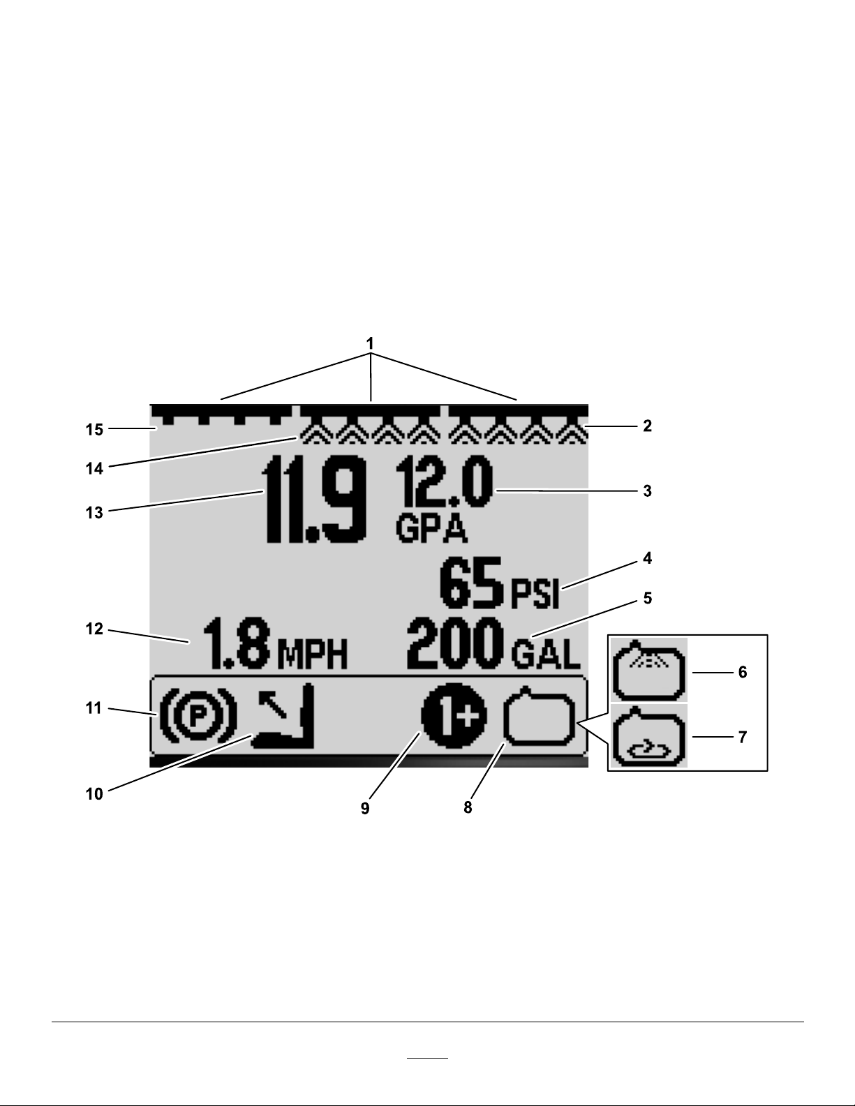
ProductOverview.....................................................2
Controls.............................................................2
Operation..................................................................3
BeforeOperation...................................................3
AccessingtheMainMenuScreen.......................3
InfoCenterMainSubMenus...............................4
CalibratingtheSprayer.....................................14
DuringOperation.................................................26
InfoCenterSprayAreaScreens........................26
InfoCenterAdvisories.......................................28
InfoCenterFaultCodes.....................................29
Maintenance...........................................................30
ServiceScreens...............................................30
DiagnosticsScreens.........................................31
AboutScreens..................................................32
Setup
BeforeUsingtheSprayer
PreparingtheMachinewhen
SprayingintheApplicationRate
Mode
1.Fillthesprayertankandfreshwatertank;refer
tollingthespraytankandllingthefresh-water
tankproceduresintheOperator’sManual.
2.Calibratethesprayersystem;refertoCalibrating
theSprayer(page14).
3.Settheapplicationratevalue(s)andactive
applicationrateforthesprayerjob;referto
SettingtheRate1orRate2Value(page5)and
SettingtheActiveRate(page4).
4.Asneeded,congurethefollowingoptional
settings:
•Settheboostpercentage;refertoSettingthe
BoostPercentage(page5).
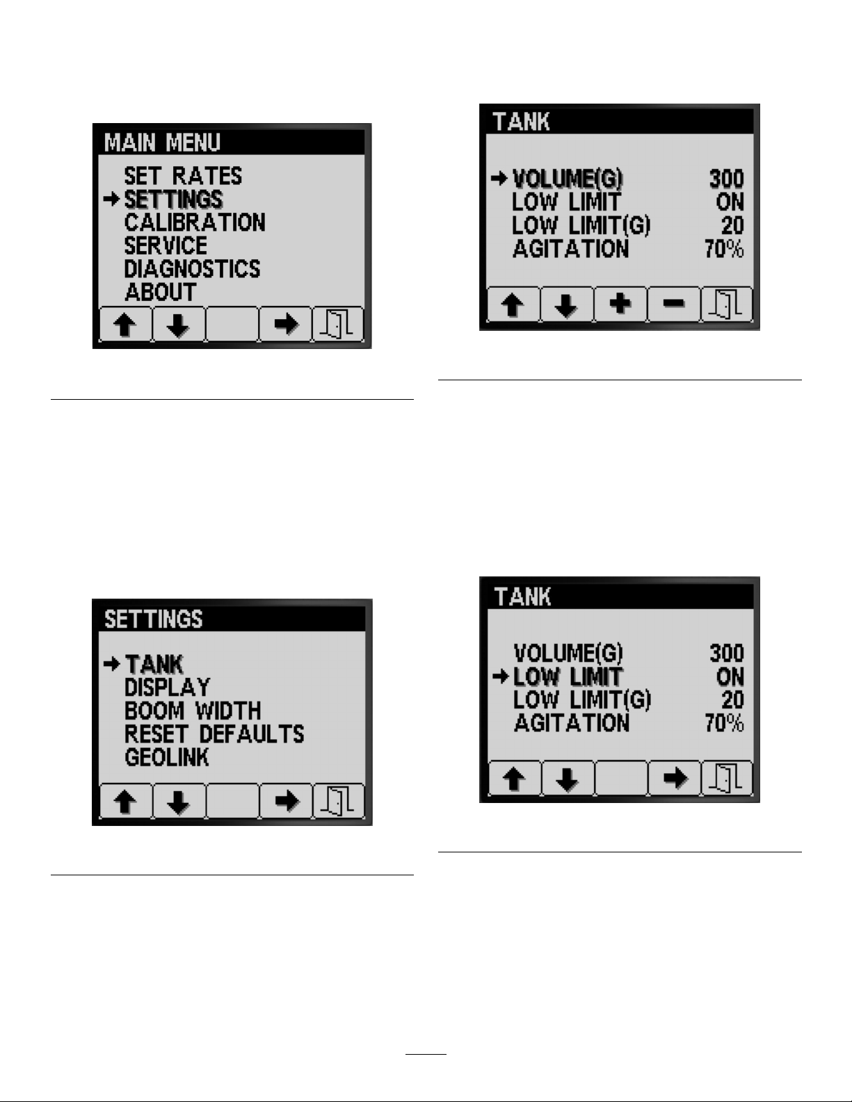
•IfyouareusingtheLOWLIMITINDICATOR,
enterthevolumeofchemicalinthesprayer
tank;refertoSettingtheTankVolume(page
6).
•Setthelowlimitindicatorandthelowlimit
volumevalueforthetank;refertoSettingthe
LowLimitIndicator(page6)andSettingthe
LowLimitVolumeValue(page7).
•Setthepresetagitationvalue;refertoSetting
thePresetAgitationValue(ApplicationRate
ModeOnly)(page7).
©2019—TheToro®Company
8111LyndaleAvenueSouth
Bloomington,MN55420
Registeratwww.Toro.com.OriginalInstructions(EN)
PrintedintheUSA
AllRightsReserved*3431-740*A

PreparingtheMachinewhen
SprayingintheManualMode
1.Fillthesprayertankandfreshwatertank;refer
tollingthespraytankandllingthefresh-water
tankproceduresintheOperator’sManual.
2.Asneeded,congurethefollowingoptional
settings:
•Optional:IfyouareusingtheLOWLIMIT
INDICATOR,enterthevolumeofchemicalin
thesprayertank;refertoSettingtheTank
Volume(page6).
•Optional:setthelowlimitindicatorandthe
lowlimitvolumevalueforthetank;referto
SettingtheLowLimitIndicator(page6)and
SettingtheLowLimitVolumeValue(page7).
ProductOverview
Controls
InfoCenterHomeScreen
Whenyoustartthemachine,thehomescreen
appears,displayingthecorrespondingiconsthat
apply(i.e.,theparkingbrakeisengaged,thesprayer
sectionsareon,youareoutoftheseat,etc.).
Note:Thefollowinggureisanexamplescreen;
thisscreenshowsallthepotentialiconsthatcould
appearonthescreenwhileoperating.
Refertothefollowinggraphicforalloftheicon
denitions(Figure1).
g191986
Figure1
1.Mastersection-switch
indicator—ON
5.Tank-volumeindicator(US
gallonsshown)
9.Active-application
rate/boost-rate
indicator—ON
13.Active-applicationrate(gpa
shown)
2.Rightsectionindicator—ON6.Rinse-system
indicator—ON(optional
kit)
10.Operatoroutofseat14.Centersection
indicator—ON
3.Target-applicationrate(gpa
shown)
7.Agitationindicator—ON11.Parking-brakeindicator15.Leftsectionindicator—OFF
4.System-pressureindicator
(psishown)
8.Spray-pumpindicator—ON12.Vehicle-speedindicator
(mphshown)
2

Master-SectionIndicator
Themaster-sectionindicatordisplayswhenthe
mastersectionswitchisintheONposition(Figure1).
Sprayer-SectionIndicators
Theleft,right,and/orcentersprayersectionsdisplay
whenanyofthesprayer-sectionswitchesareinthe
ONposition(Figure1).
Active-ApplicationRate
Theactive-applicationrateindicatestheactualrateat
whichthesprayedproductisbeingapplied(Figure1).
Target-ApplicationRate(ApplicationRateModeOnly)
Thetarget-applicationrateindicatesthetargetrate
thattheuserset(Figure1).
Note:Inapplication-ratemode,thesystemattempts
toattainthetargetratethatyouset.
Vehicle-SpeedIndicator
Thevehicle-speedindicatordisplaysthecurrent
vehiclespeed(Figure1).
System-PressureIndicator
Whensprayersectionsareactive(on),the
system-pressureindicatordisplaysthespray
pressure;whenthesprayersectionsareoff,the
agitationpre-setpressuredisplays(Figure1).
Parking-BrakeIndicator
Theparking-brakeindicatordisplaysontheHome
Screenwhentheparkingbrakeisengaged(Figure1).
Operator’s-SeatIndicator
Theoperator-seatindicatordisplaysontheHome
Screenwhentheoperatorisoutoftheseat(Figure1).
Active-ApplicationRate/Boost-RateIndicator
(ApplicationRateModeOnly)
Theactive-applicationrateindicatordisplayswhich
presetapplicationrateyouareusing(Figure1).The
boost-rateindicatordisplayswhenyoupressandhold
buttons1and5simultaneouslytoapplyaboosted
applicationrate,suchasboostingtheapplicationrate
whensprayingherbicideoverapatchofweeds.
Spray-PumpIndicator
Thespray-pumpindicatordisplayswhenthespray
pumpisrunning(Figure1).
Rinse-SystemIndicator
OptionalKit
Therinse-systemindicatordisplayswhentherinse
systemisactive(Figure1).
AgitationIndicator
Theagitationindicatordisplayswhentheagitation
valveisopen(Figure1).
Operation
BeforeOperation
AccessingtheMainMenu
Screen
FromtheHomescreen,pressandholdthebutton5
(farright)ontheInfoCentertoaccesstheMAINMENU
screen(Figure2).
g193013
Figure2
1.Button5
Fromthemainmenuscreen,youcanaccesstheSet
Ratesscreen,Settingsscreen,Calibrationscreen,
Servicescreen,Diagnosticsscreen,ortheAbout
screen(Figure3).
3

g193014
Figure3
1.Uparrow6.Button4
2.Button17.Selectarrow
3.Downarrow8.Button5
4.Button29.Exit
5.Button3
InfoCenterMainSubMenus
SetRatesScreen(Application
RateModeOnly)
1.Toaccessthesetratesscreen,pressbutton2
ontheMAINMENUscreentonavigatetotheSET
RATESoption(Figure4).
g191808
Figure4
2.Pressbutton4toselectSETRATESsub-menu
(Figure4).
ThisscreendisplaysandallowsyoutosettheActive
(application)Rate,Rate1,Rate2,andtheBoost-rate
percentage.
SettingtheActiveRate
Usetheactiveratesoptiontosetthesprayerpreset
ratetoeitherrate1orrate2.
1.Pressbutton1or2tonavigatetotheACTIVE
RATEoption(Figure5).
g191729
Figure5
2.Pressbutton4toselecttheACTIVERATEentry
(Figure5).
3.Pressbuttons3or4tosettheprogrammed
activeratetoeitherRATE1orRATE2(Figure5).
4.Pressbutton5tosavethesetting,exittheRATES
screen,andreturntotheMainscreen.
Note:Whenyouaresprayingyoucanquicklyswitch
theactiveratebetweentherate1valueandtherate
2valuefromthehomescreen.Pressbuttons1and
2simultaneouslytoselectRATE1orpressbuttons4
and5simultaneouslytoselectRATE2.
4

SettingtheRate1orRate2Value
1.Pressbutton1or2tonavigatetotheRATE1or
RATE2options(Figure6).
g191782
Figure6
2.Pressbutton4toselectthesprayerRATEoption
(Figure6).
3.Pressbuttons3or4tosettheraiseorlowerthe
sprayerrate(Figure7).
Note:Youcanchangetheratefasterby
pressingandholdingbutton3or4.
g191794
Figure7
4.Pressbutton5tosavethesetting,exittheRATE
screen,andreturntotheSETRATESscreen.
SettingtheBoostPercentage
Theboostrate%isthepercentageamountadded
totheactiveratewhenyouwanttosprayadditional
chemicaltoaturfarea,suchasadditionalherbicide
sprayedatanareaofweeds.
Note:Whileusingthesprayer,attheHomescreen
pressandholdbuttons1and5simultaneouslyto
applyboostrate.
Boostisactiveonlyaslongasyouholdbuttons1and
5,thenreturnsthesetratewhenyounolongerpress
andholdthebuttons.
1.Pressbutton1or2tonavigatetotheboost-rate
percentageoption(Figure8).
g191781
Figure8
2.Pressbutton4toselecttheBoost%setting
(Figure9).
Note:Youcansettheboostpercentageto5%,
10%,15%,20%,or25%increments.
g191807
Figure9
3.Pressbutton3or4toraiseorlowertheboost
percentage(Figure9).
Note:Examples—ifboost%=25%,whileboost
rateisactivatedthesprayervolumeis125%of
theactiverate.
4.Pressbutton5tosavetheBOOST%,exitthe
boostscreen,andreturntotheSETRATES
screen.
5

Settings
1.ToaccesstheSETTINGSscreen,pressbutton
2ontheMAINMENUscreentonavigatetothe
Settingsoption(Figure10).
g192022
Figure10
2.Pressbutton4toselectSETTINGSsub-menu
(Figure10).
Note:Thisscreendisplaysandallowsyou
tosettheT ank,Display,BoomWidth,Reset
Defaults,andGeoLinksettings.
TankSettings
1.Pressbutton1or2tonavigatetotheTANK
option(Figure11).
g191832
Figure11
2.Pressbutton4toselectTANKsub-menu(Figure
11).
ThisscreendisplaysandallowsyoutosettheT ank
Volume,LowLimit,LowLimitVolume,andPreset
Agitationsettings.
SettingtheTankVolume
1.Pressbutton1or2tonavigatetotheTANK
VOLUMEoption(Figure12).
g191833
Figure12
2.Pressbutton3or4toraiseorlowerthevalue
forthevolumeofchemicalinthesprayertank
(Figure12).
3.Pressbutton5tosavethesetting,exittheTANK
screen,andreturntotheSETTINGSscreen.
SettingtheLowLimitIndicator
1.Pressbutton1or2tonavigatetotheLOWLIMIT
option(Figure13).
g191831
Figure13
2.Pressbutton4toturnonorturnoffthelimit
indicatorforthelowtankvolume(Figure13).
3.Pressbutton5tosavethesetting,exittheTANK
screen,andreturntotheSETTINGSscreen.
6

SettingtheLowLimitVolumeValue
1.Pressbutton1or2tonavigatetotheLOWLIMIT
volumeoption(Figure14).
g191829
Figure14
2.Pressbutton4toselecttheLOWLIMITvolume
entry(Figure14).
3.Pressbutton3or4toraiseorlowerthethreshold
volumeatwhichthelimitindicatordisplaysin
theInfoCenter(Figure14).
4.Pressbutton5tosavethesetting,exittheTANK
screen,andreturntotheSETTINGSscreen.
SettingthePresetAgitationValue(Application
RateModeOnly)
Note:Thepresetagitationsettingisusedtosetthe
sprayerpumpspeedwhenthesprayerisoperated
intheApplicationRateModewithallsprayersection
shutoff.Thepresetagitationsettingcontrolsthe
percentageofsprayerpumpspeed.Thedefault
presetagitationsettingis40%.
1.Identifythetargetsprayerpressurethatyouare
planningtospray—forexample:2.76bar(40
psi).Recordthepressuredisplayedonthedash
mountedsprayer-pressuregaugebelow.
Sprayer
pressure:
2.Calculatetheinitialagitationpresetpressure
usingtheformulabelow:
Sprayeroperationpressurex1.5to2.0=initialagitationpreset
pressure
Example:targetsprayerpressure2.76bar(40psi)
x1.5=initialagitationpresetpressure4.1(60psi)
Example:targetsprayerpressure2.76bar(40psi)x2.0=initial
agitationpresetpressure5.5bar(80psi)
Recordyour
calculationhere:
3.WiththemastersectionswitchintheOFF
positionandtheenginethrottlesettotheengine
speedyouintendtorunthemachine,adjustthe
presetagitationvalueuntilthesprayersystem
pressureisbetween1.5to2.0timesthetarget
sprayerpressurethatyouidentiedinstep1.
Forexample,ifyouaresprayingat2.76bar(40
psi),initiallysetPresetAgitationtoachievea
systempressureof4.1to5.5bar(60to80psi).
Note:Ifthechemicalsinthesprayertankare
foaming,lowerthepresetagitationvalueas
necessarytoreducesystempressurewhentank
agitationisrunning.
4.Pressbutton1or2tonavigatetotheAGITATION
option(Figure15).
g191830
Figure15
5.Pressbutton4toselecttheAGITATIONentry
(Figure15).
6.Whilewatchingthedashmounted
sprayer-pressuregauge,pressbutton3
or4toraiseorlowerthepresetvalueuntilthe
sprayerpressureisattheinitialagitationpreset
pressurethatyoucalculatedinstep2(Figure
15).
Note:Donotexceed586kPa(85psi)sprayer
systempressurewhenadjustingthepreset
agitationvalue.
Note:Youmaysetthepresetagitationvalue
higherifagitationdoesnotcausethechemical
inthetanktofoam.Youmayneedtolowerthe
agitationvalueifagitationcausesthechemical
inthetanktofoam.
7.Pressbutton5tosavethesetting,exittheTANK
screen,andreturntotheSETTINGSscreen.
7

DisplaySettings
1.Pressbutton1or2tonavigatetotheDISPLAY
option(Figure16).
g191894
Figure16
2.Pressbutton4toselectDISPLAYsub-menu
(Figure16).
Note:Thisscreendisplaysandallowsyoutosetthe
UnitsofMeasure,Language,Backlighting,Contrast,
ProtectionforMenus,PINSettings,andaudioMute
settings.
SettingUnitsofMeasure
1.Pressbuttons1or2tonavigatetotheUNITS
option(Figure17).
g191891
Figure17
2.Pressbutton4toswitchbetweenENGLISH,TURF,
andSIunitsofmeasure(Figure17).
•English:mph,gallons,acre
•Turf:mph,gallons,1000ft²
•SI(metric):kph,liter,hectare
Note:Changingtheunitsofmeasuresetting
clearsthetankvolumeentryandthepresetRate
1andRate2settings.
3.Pressbutton5tosavethesetting,exittheUNITS
screen,andreturntotheSettingsscreen(Figure
17).
SettingtheDisplayLanguage
1.Pressbuttons1or2tonavigatetotheLANGUAGE
option(Figure18).
g191895
Figure18
2.Pressbutton4toselecttheLANGUAGEentry
(Figure18).
3.Pressbuttons1or2tonavigatetothelanguage
towhichyouwanttheInfoCentertodisplay
(Figure19).
g191892
Figure19
4.Pressbutton4toselectthelanguage(Figure
19).
5.Pressbutton5tosavethesetting,exitthe
LANGUAGEscreen,andreturntotheDISPLAY
screen(Figure19).
8

SettingtheDisplayBacklightingorContrast
1.Pressbuttons1or2tonavigatetotheBACKLIGHT
ortheCONTRASToption(Figure20).
g191898
g191899
Figure20
2.Pressbutton4toselecttheBACKLIGHTINGor
CONTRASTentry(Figure20).
3.Pressbuttons3or4tosetthedesireddisplay
backlightingorcontrastvalue(Figure20).
Note:Thebacklightingintensityorcontrast
changesonthedisplayoftheInfoCenterasyou
changethevalueforthesetting.
4.Pressbutton5tosavethesetting,exitthe
BACKLIGHTortheCONTRASTscreen,andreturn
totheSETTINGSscreen(Figure20).
SettingProtectionforMenus
Note:RefertoChangingPINSettings—Assessing
thePINSettingsSub-menu(page10)forrelated
information.
1.Pressbuttons1or2tonavigatetothe
PROTECTEDMENUSoption(Figure21).
g191896
Figure21
2.Pressbutton4toselectthePROTECTEDMENUS
entry(Figure21).
3.Pressbuttons1or2tonavigatetothemenu
optionthatyouwanttochangePINcode
protection(Figure22).
g191893
Figure22
4.Pressbutton4toselectthemenuoption(Figure
22).
5.Repeatsteps3and4foranyothermenusthat
youwanttochangePINcodeprotection.
6.Pressbutton5tosavethesetting,exitthe
PROTECTEDMENUSscreen,andreturntothe
DISPLAYscreen(Figure22).
9

ChangingPINSettings—AssessingthePIN
SettingsSub-menu
1.Pressbuttons1or2ontheDISPLAYscreento
navigatetothePINSETTINGSoption(Figure23).
g034290
Figure23
2.Pressbutton4toselectPINSETTINGSsub-menu
(Figure23).
3.Pressbuttons1through4toenteryourPIN
code.WhenyoucompleteenteringthePIN,
pressbutton5(Figure24).
Note:Eachtimeyoupressthesamebuttonto
enteraPINdigit,thenumberincreasesinvalue.
g034292
Figure24
1.Digit14.Digit4
2.Digit25.EnterPIN
3.Digit3
ChangingPINSettings—SettingPINEntry
Requirements
1.Pressbuttons1or2toselectthePINENTRY
option(Figure25).
g034291
Figure25
2.Pressbutton4toturnthePINrequirementON
orOFF(Figure25).
3.Pressbutton5tosavethesetting,exitthePIN
SETTINGSscreen,andreturntotheDISPLAY
screen.
10

ChangingPINSettings—ChangingthePIN
Code
1.Pressbuttons1or2toselectthePINCHANGE
option(Figure26).
g034303
Figure26
2.Pressbutton4toselectthePINCHANGEentry
(Figure26).
3.Pressbuttons1through4toenteryourPIN
code.WhenyoucompleteenteringthePIN,
pressbutton5(Figure24).
Note:Eachtimeyoupressthesamebuttonto
enteraPINdigit,thenumberincreasesinvalue.
4.AttheenteroldPINscreen,pressbuttons1
through4toenteryouroldPINcode,andpress
button5whenyoucompletethePIN(Figure24).
Note:ThedefaultPINcodewhenyouinitially
createyourPINis1234.
g034306
Figure27
1.Digit14.Digit4
2.Digit25.EnterPIN
3.Digit3
5.AttheenternewPINscreen,pressbuttons1
through4toenteryournewPINcode.When
youcompleteenteringthePIN,pressbutton5
(Figure28).
g034307
Figure28
1.Digit14.Digit4
2.Digit25.EnterPIN
3.Digit3
11

6.Attheconformscreen,pressbuttons1through4
toenteryournewPINcode.Whenyoucomplete
enteringthePIN,pressbutton5(Figure29).
g034308
Figure29
1.Digit14.Digit4
2.Digit25.EnterPIN
3.Digit3
Note:Afteryouconrmthepincode(Figure
29),thePinCorrectscreenappearsfor
approximately5seconds.
MutingtheAudioIndicator
Note:SettingthemuteaudioindicatortoOnmutes
theaudiosignalfortheInfoCenteronly—nottheaudio
warningforthemachine.
1.Pressbuttons1or2tonavigatetotheMUTE
option(Figure30).
g191890
Figure30
2.Pressbutton4toturntheaudioindicatorONor
OFF(Figure31).
g191889
Figure31
3.Pressbutton5tosavethesetting,exitthe
MUTEscreen,andreturntotheSETTINGSscreen
(Figure31).
SettingtheBoomWidths
Theboom-widthsettingsarepre-populatedatthe
manufacturingplant.
1.Pressbutton2ontheSettingsscreenuntilyou
reachtheBOOMWIDTHoption(Figure32).
g191711
Figure32
2.Pressbutton4toselecttheBOOMWIDTHSentry
(Figure32).
3.Pressbutton2toselecttheboomsectionthat
youwanttoeditthewidth(Figure33).
12

g224287
Figure33
4.Pressbutton3orbutton4tolowerorraisethe
boomwidthvalue(Figure33).
5.Pressbutton5tosaveyoursettingsandexitthe
BOOMWIDTHscreen,andreturntotheSETTINGS
screen(Figure33).
ResettingtheDefaultSettings
1.Pressbutton2ontheSETTINGSscreenuntilyou
reachtheRESETDEFAULTSoption(Figure34).
g191706
Figure34
2.Pressbutton4toselecttheRESETDEFAULTS
entry(Figure34).
3.Pressbutton1or2toselect1ofthefollowing
optionsthatyouwanttoresettofactorysetting:
•Display
•FlowCalibration
•SpeedCalibration
•AllOthers
g191707
Figure35
4.Pressbutton4toresetthesettingsforthe
selectedoption(Figure35).
5.Repeatsteps3and4forotheroptionsthatyou
wanttoreset(Figure35).
6.Pressbutton5tosaveyoursettingsandexit
theRESETDEFAULTSscreen,andreturntothe
SETTINGSscreen(Figure35).
SettingtheGeoLinkOption
1.Pressbutton1or2ontheSETTINGSscreenuntil
youreachtheGEOLINKoption(Figure36).
g191703
Figure36
2.Pressbutton4toselecttheGeoLinkentry
(Figure36).
3.OntheGeoLinkmenu,pressbutton4toselect
theYesoptionorpressbutton4toselectthe
Nooption,andpressthebutton5tosaveyour
settingsandexitthemenu(Figure37).
Note:TurnontheGeoLinksettingonlyifyou
havetheoptionalGeoLinksysteminstalledon
themachine.
13

g191701
g191700
Figure37
4.RotatetheignitionswitchtotheOFFposition
andthentotheONposition(Figure37).
g191705
Figure38
5.Pressbutton5tosaveyoursettingsandexit
theGEOLINKscreen,andreturntotheSETTINGS
screen(Figure38).
CalibratingtheSprayer
ApplicationRateMode
Note:T ocalibratethesprayerformanualmode
operation,refertosettingthesection—bypassvalves
intheOperator’sManualforthemachine.
1.Ensurethatthesprayertankisclean;referto
CleaningtheSprayerSystemintheOperator’s
Manual.
2.ToaccesstheCalibrationscreenpressbuttons
1or2ontheMAINMENUscreentonavigateto
theCALIBRATIONoption(Figure39).
g192024
Figure39
3.Pressbutton4toselectCalibrationsub-menu
(Figure39).
Note:Thisscreendisplaysandallowsyou
tocalibratetheowmeterinput,calibratethe
speedsensorinput,performaspeedtest,and
manuallyentercalculationdata.
FlowCalibration
Customerprovidedequipment:Useacatch
containergraduatedforthenozzle-owrateasfollows:
•1.5L/pm(0.4gpm)orless-acontainergraduated
in10ml(1/2oz)incrementsispreferred.
•1.9L/pm(0.5gpm)ormore-acontainergraduated
in20ml(1oz)increments.
Important:Youmustperformaowcalibration
for3sprayersectionseachtimeyoureplace
allnozzles,changetotheactivespray(down)
position,orafterreplacingtheowmeter.You
shouldperformaowcalibrationfor3sprayer
sectionsifyoureplaceseveralwornnozzles.
Note:Incorrectlyperformingthecatchtestresults
ininaccuracyinowcalibration.Theresultofthese
inaccuraciescausesthesprayersystemtoover-apply
orunder-applysprayerchemicals.
14

EvaluatingtheWhichTypeofFlowCalibration
toPerform
UsetheSprayerSectionsTabletohelpdetermine
howyoutypicallysprayturfwiththemachineand
whichowcalibrationtoperform.
Note:Youcanperformacombinationofupto3ow
calibrationtypes.
SprayerSectionTable
Performthe3-boomcalibration
3sprayersectionsYes
Ialsospraywith2
sprayersections:
Performthe2-Boom
Calibration
LeftandCenter
sections(OR)
YesNo
RightandCenter
sections(OR)
YesNo
RightandLeft
sections
YesNo
Ialsospraywith1
sprayersection:
Performthe1-Boom
Calibration
Leftsprayersection
only(OR)
YesNo
Centersprayer
sectiononly(Or)
YesNo
Rightsprayer
sectiononly
YesNo
3boomcalibration:Alwaysperformthecalibration
forthe3sprayersectionswhenyouchangethe
nozzlestoincreaseordecreasetherangeof
applicationrates.
Note:Ifyoudonotperformtheoptional2boom
calibrationor1boomcalibration,thesprayeruses
thecalculationsfromthe3-boomcalibrationinall
sprayer-sectioncombinations.
Optional2boomcalibration:Calibratetheleftand
centersprayersectionsortherightandcentersprayer
sectionsortheleftandrightsectionsifyoutypically
spraywiththosesectioncombinations.Performthis
optionalcalibrationafterperformingthe3sprayer
sectioncalibration.
Note:Thecalibrationyouperformfortwosprayer
sectionsisusedwheneveryouspraywithany
combinationof2sprayersections.
Note:Youcancalibrateonlyfor1pairofsprayer
sectionsforthe2-boomcalibration.Calibratefromthe
pairofsprayersectionsthatyouusethemost.The
sprayersystemusesthe2-boomcalculationwhen
youspraywitheithertheleftandcenterorrightand
centersectioncombinations.
Optional1boomcalibration:Calibratetheleft
orcenterorrightsprayersectionifyoutypically
spraywith1sprayersection.Performthisoptional
calibrationafterperformingthe3-sprayer-section
calibrationand2-sprayer-sectioncalibration.
Note:Youcancalibrateonly1ofthe3sprayer
sectionsforthe1boomcalibration.Calibratefromthe
sprayersectionthatyouusethemost.Thesprayer
systemusesthe1-boomcalibrationwhenyouspray
withtheleft,center,orrightsection.
PreparingfortheFlowTest
1.Ensurethatthenozzlesthatyouintendtouse
areintheactivespray(down)position(Figure
40).
Important:Allnozzlesintheactiveposition
mustbethesamecolor.
Note:Forbestresults,nozzlesintheactive
positionshouldhaveapproximatelythesame
amountofwear.
g192604
Figure40
1.Reservenozzleposition2.Activesprayposition
2.Pressbuttons1or2ontheCALIBRATION
sub-menutonavigatetotheFLOWoption(Figure
41).
15

g192583
Figure41
3.Pressbutton4toselectFlowcalibrationoption
(Figure41).
4.Fillthesprayertankhalffull—600Lor150US
gallonsofwater(Figure42).
Note:Youcancanceltheowcalibration
bypressingbutton5.Amessagedisplays
conrmingthatyoucanceledtheowcalibration.
g192582
Figure42
5.Engagetheparkingbrake(Figure42).
6.Starttheengineandlowertheoutersections.
7.SetthepumpswitchtotheONposition(Figure
43).
g192636
Figure43
1.Sprayer-pumpswitch3.Throttle
2.Agitationswitch
8.MovethethrottletotheFASTposition(Figure
43)andallowtheenginetorunfor10minutes.
Important:Youmustbringthehydraulic
systemtooperatingtemperaturebefore
proceedingwiththeremainingow
calibrationsteps.
PreparingfortheCatchTest
1.Pressbutton2toadvancetothenextstep
(Figure42).
2.Pressbuttons3or4toselectthenozzles
installedattheactivespraypositionasfollows:
•Formachineswithnozzlecolorsthatmatch
theowratesdescribedinFigure44,select
thecolorofnozzlesinstalledattheactive
sprayposition.
•Formachineswithnozzlecolorsthatdonot
matchtheowratesdescribedinFigure44,
selecttheowrate(L/pmorgpm)ofnozzles
installedattheactivesprayposition.
16

g192605
Figure44
3.Pressbutton2toadvancetothenextstep
(Figure44).
4.Setthesprayermodeswitchtothemanual
position(Figure45).
g192606
g192608
Figure45
1.Manualmodeposition2.Sprayer-modeswitch
5.Rotatetheknobforthesection-bypassshutoff
valvetotheclosedposition(Figure45).
g192607
Figure46
1.Section-bypassshutoffvalve(closedposition)
6.SettheagitationswitchtotheOFFpositionand
setthethrottletotheFASTposition(Figure43).
7.Pressbutton2toadvancetothenextstep
(Figure45).
PreparingtheSprayerSection(s)fortheCatch
Test
1.Setthesprayersectionswitchesasfollows:
Note:RefertoPreparingfortheFlowTest
(page15).
•Selecttheleft,center,andrightsection
switchesfora3-sprayer-section
calibration.
Important:Youmustperformthis
calibration.
•Selectthe2sprayersectionswitchesforthe
sprayersectionsyouidentiedinEvaluating
theWhichTypeofFlowCalibrationto
Perform(page15)forthe2-sprayer-section
calibration.
Note:Performthisoptionalcalibrationafter
performingthe3-sprayer-sectioncalibration.
•Selecttheleftorcenterorrightsection
switchthesprayersectionyouidentied
inEvaluatingtheWhichTypeofFlow
CalibrationtoPerform(page15)forthe
1-sprayer-sectioncalibration
Note:Performthisoptionalcalibrationafter
performingthe3-sprayer-sectioncalibration
and2-sprayer-sectioncalibration.
17

g192867
g192944
Figure47
1.Leftspray-sectionswitch3.Rightspray-sectionswitch
2.Centerspray-section
switch
4.Mastersectionswitch
2.Pressbutton2toadvancetothenextstep
(Figure47).
3.AttheRepeattheFollowingTestscreen,press
button2tostartthesprayersectioncatchtest
(Figure48).
g192945
Figure48
PerformingtheSprayerSectionCatchTest
Note:Readythegraduatedcatchcontainer.
1.SetthemastersectionswitchtotheONposition
(Figure47).
2.Usetheapplication-rateswitchtoadjustthe
sprayersystempressuretoapproximately276
kPa(40psi);refertoFigure49.
g192699
Figure49
1.Pressuregauge(sprayer
system)
2.Application-rateswitch
3.SetthemastersectionswitchtotheOFFposition
(Figure47).
4.Atthecatchtestplaybackscreen,conrmthe
numberofbooms,thenozzlecolor,andpress
button3tostartthecatchtest(Figure50).
Note:Youhave14secondstomovetothe
backofthemachineandpositionthegraduated
catchcontainerunderaspraynozzleforthe
catchtestperiod.
18

g192976
Figure50
Note:Thesprayersystemautomaticallyopens
thesectionvalve,thesprayernozzlessprayfor
thecatchtestperiod,andthesprayersystem
automaticallyshutsoffthesectionvalve.
5.Catchthewaterfromthesprayernozzleuntilthe
sprayerowshutsoff(Figure51).
g193177
Figure51
6.Setthegraduatedcontaineronalevelsurface
andnotetheuidvolume(Figure52).
Important:Whenyouarereadingthe
graduatedcontainer,setthecontainerona
levelsurface.
Important:Whenyouarereadingthe
graduatedcontainer,readtheuidvolumein
thegraduatedcontaineratthelowestpoint
oftheuid-surfacecurve.
Important:Smallerrorsreadingthe
uidvolumeinthegraduatedcontainer
signicantlyimpactstheaccuracyofthe
sprayercalibration.
g193416
Figure52
1.Highestpointofthe
uid-surfacecurve(donot
measurehere)
3.Levelsurface
2.Lowestpointofthe
uid-surfacecurve
(measurehere)
7.Comparethevolumeofuidinthegraduated
catchcontainerwiththeTargetVolumedisplayed
ontheInfoCenterscreen(Figure52).
Note:Youneedthevolumeofuidinthe
graduatedcatchcontainer±7.4ml(1/4oz)of
theT argetVolumedisplayedontheInfoCenter
screen.
8.Iftheuidlevelinthegraduatedcatchcontainer
is7.4ml(1/4oz)morethatthetargetvolume
or7.4ml(1/4oz)lessthanthetargetvolume,
perform1ofthefollowing:
•Ifthevolumeofuidinthegraduatedcatch
containeris±7.4ml(1/4oz)oftheT arget
VolumedisplayedontheInfoCenterscreen,
pressbutton2.
•Ifthevolumeistoolow,usethe
application-rateswitchtoraisethesprayer
19

systempressureandproceedtothenext
step.
•Ifthevolumeistoohigh,usethe
application-rateswitchtolowerthesprayer
systempressureandproceedtothenext
step.
9.Repeatsteps4through8untilthevolumeof
uidinthegraduatedcatchcontainer±7.4ml
(1/4oz)oftheT argetVolumedisplayedonthe
InfoCenterscreen.
10.Pressbutton2toproceedtoPerformingthe
CalibrationCalculation(page20).
PerformingtheCalibrationCalculation
1.SetthemastersectionswitchtotheONposition
(Figure53).
g192853
Figure53
2.Pressbutton2toadvancetobeginthe
calibrationcalculation(Figure53).
Note:TheInfoCenterdisplaysthecalibrationin
processscreen(Figure54).
Note:Thesprayersectionsspraysoutfor3
minuteswhilethemachineiscalculatingthe
calibrationcorrection.
g192852
Figure54
Whenthecalibrationprocessends1ofthe
followingmessagesisdisplayed:
•Amessagedisplaysconrmingthattheow
calibrationissuccessful(Figure55).
g192866
Figure55
•Amessagedisplaysindicatingthattheow
calibrationhasfailed(Figure56).
g192865
Figure56
20
This manual suits for next models
2
Table of contents
Other Toro Paint Sprayer manuals

Toro
Toro 41228 User manual

Toro
Toro GeoLink 41623 User manual

Toro
Toro 41199 User manual

Toro
Toro GeoLink CL-55 User manual

Toro
Toro 41249 User manual

Toro
Toro 41394 User manual

Toro
Toro Multi Pro 5800 41623 User manual

Toro
Toro SprayMaster 34246 User manual

Toro
Toro Multi Pro ExcelaRate 5800-G User manual

Toro
Toro 41440 Specifications

Toro
Toro 41581 User manual

Toro
Toro Multi Pro 5800-D User manual

Toro
Toro Multi Pro 5800 User manual

Toro
Toro Multi Pro 41118 User manual

Toro
Toro 41621 User manual

Toro
Toro Multi Pro 41602 User manual

Toro
Toro 41605 User manual

Toro
Toro MULTI PRO 5600 User guide

Toro
Toro Multi Pro 5800-D User manual

Toro
Toro Multi Pro 1250 User manual