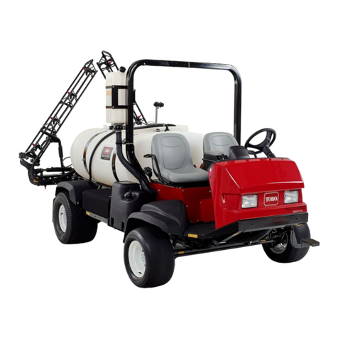
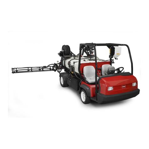
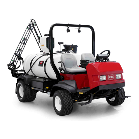
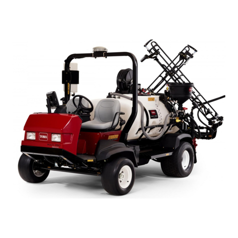
Toro 41228 User manual

FormNo.3353-750RevC
FoamMarkerKit
forMulti-Pro1200,1250,5600and5700TurfSprayersand
Workman200SpraySystems
ModelNo.41228—SerialNo.260000001andUp
InstallationInstructions
Note:Determinetheleftandrightsidesofthemachinefromthenormaloperatingposition.
Note:Ifyouareinstallingthiskitonamachineequippedwithanenclosedboomsystem,usetheseinstructions
alongwiththeenclosedboomsysteminstructions.
Note:Ifyouareinstallingthiskitonamachineequippedwithacab,abracketfromCustomProducts(partnumber
2–15904)needstobeinstalledaswelltoeliminatetheinterferencewiththecab.
Note:RTVsiliconesealantisusedintheinstallationofthiskit.
Safety
SafetyandInstructionalDecals
Safetydecalsandinstructionsareeasilyvisibletotheoperatorandarelocatednearanyareaof
potentialdanger.Replaceanydecalthatisdamagedorlost.
94-7275
94-7287
©2008—TheToro®Company
8111LyndaleAvenueSouth
Bloomington,MN55420
Registeratwww.Toro.com.OriginalInstructions(EN)
PrintedintheUSA.
AllRightsReserved

Installation
LooseParts
Usethechartbelowtoverifythatallpartshavebeenshipped.
ProcedureDescriptionQty.Use
Tank/compressorassembly1
Supplyhose,108inches2
Multi-Pro1200seriesadapterbracket1
Workmanadapterbracket1
Mudap1
Mudapbracket1
Bolt(3/8x1inch)4
Flangelocknut,serrated(3/8inch)2
Locknut(3/8inch)1
Carriagebolt,(3/8x1-1/4inches)4
Flangelocknut,non-serrated(3/8inch)4
Flangebolt(5/16x3/4inch)3
Locknut(5/16inch)3
Flatwasher(3/8inch)4
1
Hoseclamp,small2
Installthetank,compressorandmixer.
Bolt(3/8x1inch)1
Locknut(3/8inch)1
Mixerassembly1
2Flatwasher(3/8inch)2
Installthemixertee.
Wiringharness1
Hoseclamp,small6
3Plasticties12
Wirethekit.
Rockerswitch2
4Fuse,15-amp1Installtheswitchesandfuse.
Boomhose2
Grommet2
Punched-holeboomcap2
Extensionhose2
Hoseclamp,large2
5
Partscatalog1
Completetheinstallation
SeparateinstructionsfortheinstallationoftheFoam
MarkerkitaredenotedineachstepoftheSetup
wherespecicproceduresdeviatefromonemachine
toanother.Pleaselookfortheheadingdescribing
instructionsspecictothemachineyouareworking
withbeforeproceedingwitheachstepoftheSetup.
2

1
InstallingtheTank,
Compressor,andMixer
Partsneededforthisprocedure:
1Tank/compressorassembly
2Supplyhose,108inches
1Multi-Pro1200seriesadapterbracket
1Workmanadapterbracket
1Mudap
1Mudapbracket
4Bolt(3/8x1inch)
2Flangelocknut,serrated(3/8inch)
1Locknut(3/8inch)
4Carriagebolt,(3/8x1-1/4inches)
4Flangelocknut,non-serrated(3/8inch)
3Flangebolt(5/16x3/4inch)
3Locknut(5/16inch)
4Flatwasher(3/8inch)
2Hoseclamp,small
Procedure
MultiPro1200or1250TurfSprayer
1.MounttheMulti-Pro1200seriesadapterbracket
totherightsideofthevehicleabovethebattery
(Figure1)using4carriagebolts(3/8x1-1/4inches)
and4angelocknuts(3/8inch).
Note:Itiseasiestifyouremovethebatterybefore
performingthisstep.RefertoyourvehicleOperator’s
Manualforinstructions.
Figure1
1.Battery3.Carriagebolt(3/8x1-1/4
inches)
2.Multi-Pro1200series
adapterbracket
4.Flangelocknut,
non-serrated(3/8inch)
2.Removethe4bolts(1/4x1inch)andatwashers
thatholdthecovertothetank/compressorassembly
andremovethecover(Figure2).
Figure2
1.Cover4.Bolt(1/4x1inch)
2.Tank/compressor
assembly
5.Bottomrightbolt
3.Flatwasher
3.Setthecoverandfastenersaside.
4.Marka108inchsupplyhosewithablackmarkerat
eachend(Figure3).
3

Figure3
1.Compressorhose3.Tothemixertee
2.Needlevalvehose
5.Connectthemarkedsupplyhosetothehosebarb
atthecompressorandtheothersupplyhosetothe
hosebarbontheneedlevalve(Figure3).
6.Securethehoseendswithsmallhoseclamps.
7.Routebothofthesupplyhosesrearwardalongthe
rightsideofthesprayertotherearofthemachine
followingthesprayerwiringharness.
8.Attachthecovertothetank/compressorassembly
using4hex-headbolts(1/4x1inch)and4at
washersthatyouremovedpreviously.
9.Installthetank/compressorassemblytothe
Multi-Pro1200seriesadapterbracketusing2bolts
(3/8x1inch),2atwashers(3/8inch)asshown
Figure4.
Figure4
1.Tank/compressor
assembly
3.Bolt(3/8x1inch)
2.Multi-Pro1200series
adapterbracket
4.Flatwasher(3/8inch)
MultiPro5600/5700TurfSprayer
1.Remove4bolts(1/4x1inch)andatwashersthat
holdthecovertothetank/compressorassembly
(Figure5).
Figure5
1.Cover4.Bolt(1/4x1inch)
2.Tank/compressor
assembly
5.Bottomrightbolt
3.Flatwasher
2.Removethecover.
3.Setthecoverandfastenersaside.
4.Marka108inchsupplyhosewithablackmarkerat
eachend(Figure6).
Figure6
1.Compressorhose3.Tothemixertee
2.Needlevalvehose
5.Connectthemarkedsupplyhosetothehosebarb
atthecompressorandtheothersupplyhosetothe
hosebarbontheneedlevalve(Figure9).
6.Securethehoseendswithsmallhoseclamps.
7.Routebothofthesupplyhosesrearwardalongthe
leftsideofthesprayertotherearofthemachine
followingthesprayerwiringharness.
4

8.Mountthetank/compressorassemblytotheright
stepframeusing2bolts(3/8x1inch)and2at
washers(Figure7).
Figure7
1.Rightstepframe2.Tankassemblyframe
Note:Youmustinstallthefastenersfromthe
backsideofthestepframe.
9.Attachthecovertothetank/compressorassembly
using4hex-headbolts(1/4x1inch)and4at
washersthatyouremovedpreviously.
Workman200SpraySystem
1.Removethe4bolts(1/4x1inch)and4atwashers
thatholdthecovertothetank/compressorassembly
andremovethecover(Figure8).
Figure8
1.Cover4.Bolt(1/4x1inch)
2.Tank/compressor
assembly
5.Bottomrightbolt
3.Flatwasher
2.Setthecoverandfastenersaside.
3.Marka108inchsupplyhosewithablackmarkerat
eachend(Figure9).
Figure9
1.Compressorhose3.Tothemixertee
2.Needlevalvehose
4.Connectthemarkedsupplyhosetothehosebarb
atthecompressorandtheothersupplyhosetothe
hosebarbontheneedlevalve(Figure9).
5.Securethehoseendswithsmallhoseclamps.
6.Routebothofthesupplyhosesrearwardalongthe
leftsideofthesprayertotherearofthemachine
followingthesprayerwiringharness.
7.Removetherubberstripingonthebacksideofthe
tankcover(Figure10).
Figure10
1.Rubberstrip4.Mudap
2.Tankcover5.Bolt(5/16x3/4inch)
3.Mudapbracket6.Locknut(5/16inch)
8.Locatethemudapandmudapbracketinloose
parts.Installthemudaptothetankcover.Secure
theapusingthebracket,threebolts(5/16x3/4
5

inch)andthreelocknuts(5/16inch)asshownin
Figure10.
9.Attachthecovertothetank/compressorassembly
using3ofthe4hex-headbolts(1/4x1inch)and
atwashersthatyouremovedpreviously.Leavethe
bottomrightboltoutuntillaterintheinstallation
(Figure8).
10.MounttheWorkmanadapterbracketsuppliedinthe
kittothetank/compressorassemblyusing2bolts
(3/8x1inch),2atwashers(3/8inch)asshown
Figure11.
Note:Ifnecessary,cutbacktherubbertrimonthe
coversothatitdoesnotinterferewhenmounting
thebrackettothetank/compressorassembly.
Figure11
1.Workmanadapterbracket4.Flatwasher
2.Tank/compressor
assembly
5.Bolt(1/4x1inch)
3.Bolt(3/8x1inch)6.Flatwasher(1/4inch)
11.Installtheremainingbolt(1/4x1inch)andat
washer(1/4inch)throughtheWorkmanadapter
bracketandcoverintothetank/compressor
assembly(Figure11).
12.Removethelefthandleandfastenersfromtheleft
sideofthetankskid.Savefastenersforlateruse.
13.Mountthefoammarkerassemblytotheframeusing
twobolts(3/8x1inch),twowashers(3/8inch),two
angenuts(3/8inch)includedinlooseparts;and
thelefthandleandfastenersremovedpreviously
(Figure12).
Note:Rotatethetanksothatthehandleisclosest
totheframe.
Figure12
1.Foammarkerassembly5.Flangenut,serrated(3/8
inch)
2.Frame6.Leftsprayerhandle
3.Bolt(3/8x1inch)7.Fasteners
4.Washer(3/8inch)
2
InstallingtheMixerTee
Partsneededforthisprocedure:
1Bolt(3/8x1inch)
1Locknut(3/8inch)
1Mixerassembly
2Flatwasher(3/8inch)
Procedure
Forallsprayers,serialnumber259999999andlower
1.Attherearofthemachine,mountthemixer
assemblyfacingrearwardtothebracketonthe
centerboomassemblywithabolt(3/8x1inch),at
washer,andlocknut(Figure13).
6

Figure13
1.Mixerteeassembly2.Centerboom
Note:IfnecessaryonWorkman200SpraySystems,
rotatethemixerassemblydownsothatitdoesnot
interferewiththepump.
2.Locatethesupplyhosesroutedtotherearofthe
machinepreviously.
3.Slidethemarkedsupplyhoseontothebarbonthe
checkvalvelocatedattheteeassembly(Figure14).
Figure14
1.Checkvalve4.Rightboomhose
2.Hosefromthecompressor5.Leftboomhose
3.Hosefromtheneedle
valve
4.Connecttheothersupplyhosetothebarbed“Y”at
theteeassembly(Figure14).
5.Securethehoseswithsmallhoseclamps.
6.Connecttherightboomhosetotherightside
solenoidvalveassemblyandtheleftsupplyhoseto
theleftsidesolenoidassembly.
7.Securebothhoseswithsmallhoseclamps
(Figure14).
Forallsprayers,serialnumber260000001andhigher
1.Attherearofthemachine,mountthemixer
assemblyontheforwardfacingsideofthecenter
boomassemblywithabolt(3/8x1inch),atwasher,
andlocknut(3/8inch)asshowninFigure15.
Figure15
1.Centerboom4.Bolt
2.Rightboommountbracket5.Locknut
3.Mixerteeassembly6.Flatwasher
2.Locatethesupplyhosesroutedtotherearofthe
machinepreviously.
3.Slidethemarkedsupplyhoseontothebarbonthe
checkvalvelocatedattheteeassembly(Figure16).
Figure16
1.Checkvalve4.Rightboomhose
2.Hosefromthecompressor5.Leftboomhose
3.Hosefromtheneedle
valve
4.Connecttheothersupplyhosetothebarbed“Y”at
theteeassembly(Figure16).
5.Securethehoseswithsmallhoseclamps.
7

6.Connecttherightboomhosetotherightside
solenoidvalveassemblyandtheleftsupplyhoseto
theleftsidesolenoidassembly.
7.Securebothhoseswithsmallhoseclamps
(Figure16).
3
WiringtheKit
Partsneededforthisprocedure:
1Wiringharness
6Hoseclamp,small
12Plasticties
Procedure
MultiPro1200or1250TurfSprayer
1.Locatethelabeledconnectorswiringharnessforthe
foammarkersolenoidandcompressorandmake
theconnectionstothecompressorandthesolenoid
locatedatthefoamtank/compressorassembly
(Figure17).
Note:Bothoftheplugconnectionsareidentical
(Figure17).
Figure17
1.Wiringharness3.Solenoid
2.Compressor
2.Attherearofthemachine,plugtheharness
connectorsintotheboomsolenoidassemblies.
Plugtheconnectorwiththebluewiretotheright
solenoid;plugtheconnectorwiththeorangewireto
theleftsolenoid(Figure18).
Figure18
1.Mixerteeassembly3.Wiringharness
2.Boomsolenoids
MultiPro5600/5700TurfSprayer
1.Locatethewiringharnessconnectorsfurnished
withthevehicleforthefoammarkerandmakethe
connectionstothecompressorandthesolenoid
locatedatthefoamtank/compressorassembly
(Figure19).
Note:Theconnectorsarelocatedalongtheright
sideframerailstrappedtothevehicleharness,where
thetank/compressorisinstalled.Bothoftheplug
connectionsareidentical(Figure19).
Figure19
1.Wiringharness3.Solenoid
2.Compressor
2.Locatethewiringharnessconnectorfurnishedwith
thevehicleforthefoammarkerboomsolenoidat
thecentersectionoftheboom(Figure20).
8

Figure20
1.Mixerteeassembly3.Wiringharness
2.Boomsolenoids
3.Plugtheharnessconnectorsintotheboomsolenoids
atthemixerteeassembly.Plugtheconnectorwith
thebluewiretotherightsolenoidandplugthe
connectorwiththeorangewiretotheleftsolenoid
(Figure20).
Workman200SpraySystem
1.Locatethewiringharnessandmaketheconnections
tothecompressorandthesolenoidlocatedatthe
foamtank/compressorassembly(Figure21).
Note:Bothoftheplugconnectionsareidentical
(Figure21).
Figure21
1.Wiringharness3.Solenoid
2.Compressor
2.Locatetheconnectorsintherearwiringharnessof
thesprayer(Figure22).
A.Plugtheconnectorwiththeyellow/bluewire
intotheleftboomsolenoid.
B.Plugtheconnectorwiththeblue/greenwireinto
therightboomsolenoid.
Figure22
1.Mixerteeassembly3.Boomsolenoid,left
2.Boomsolenoid,right4.Wiringharness
3.Routethehosesalongthewiringharnesstotherear
ofthesprayerandtothemixerteeusingthecable
ties.Securethehoseendwithasmallhoseclamp.
4
InstallingtheSwitchesand
Fuse
Partsneededforthisprocedure:
2Rockerswitch
1Fuse,15-amp
Procedure
MultiPro1200or1250TurfSprayer
1.Removethespraycontrolpaneltoexposethe
bottomside.
2.Liftandremovethe2plugsfromthespraycontrol
panelonthevehicleandinstallthe2rockerswitches
providedintheirplace(Figure23forthe1250and
Figure24forthe1200).
9

Figure23
1250
1.Plug3.Notch(atback)
2.Switch4.Spraycontrolpanel
Figure24
1200
1.Foammarkerswitches2.Spraycontrolpanel
3.Plugtheconnectorwiththeorangewirefortheright
foamsolenoidtotherightswitchandtheconnector
withthebluewirefortheleftfoamsolenoidtothe
leftswitch.
Note:Ensurethattheorientationoftheswitches
matcheswhatisshowninFigure23,withthenotch
pointingtowardtherearofthevehicle.
4.Insertthe15-ampfuseinthecorrespondingslotin
thefuseblock(atthefrontofthevehicle).
MultiPro5600/5700TurfSprayer
1.Removethethrottleknobbyunscrewingitfromthe
throttlerodatthecenterconsole.
2.Releasethelatchandremovetheswitchpanel
assemblyfromthecenterconsoleassembly
(Figure25).
Figure25
1.Controlpanel3.Foammarkerswitches
2.Latch
3.Removethefoammarkerswitchholeplugs.
4.Installthe2rockerswitchesintotheswitchpanel.
Note:Ensurethatthenotch/holeonthebottomof
eachswitchisorientedtowardtherearofthevehicle.
5.Plugtheharnessconnectorsfoundinthecenter
consoleintothefoammarkerswitches.
Note:Theplugsintheharnessaremarked:Boom
foamRS/LSswitch.Theleftconnectorhasaorange
wirewithabluestripeandtherightconnectorhasa
bluewirewithagraystripe.
6.Installtheswitchpanelandsecurethelatch.
7.Screwthethrottleknobontothethrottleroduntil
itishandtight.
8.Insertthe15-ampfuseinthecorrespondingslotin
thefuseblock(atthefrontofthevehicle).
Workman200SpraySystem
1.Loosenthe4screwssecuringthefrontpaneltothe
controlbox(Figure26).
2.Removethefrontpanelexposetheinsideofthe
controlbox(Figure26).
10

Figure26
1.Screw4.Plug
2.Frontpanel5.RockerSwitch
3.Controlbox6.Connectors
3.Liftandremovethe2plugsfromthespraycontrol
panelonthevehicleandinstallthe2rockerswitches
providedintheirplace(Figure26).
4.Plugtheconnectorwiththeyellow/bluewiretothe
leftswitchandtheconnectorwiththeblue/green
wiretotherightswitch.
Note:Ensurethattheorientationoftheswitches
mateswiththeorientationoftheconnector.
5.Installthefrontcontrolpaneltothecontrolboxand
secureitwiththe4screwsloosenedpreviously.
6.Insertthe15-ampfuseinthetopslotinthefuse
block.Makesurethecorrespondingwireinthe
fuseblockisconnectedtothered/blackwireinthe
harness(Figure27).
Figure27
1.15-amp3.Fuseboxdecal
2.Fuseblock
5
CompletingtheInstallation
Partsneededforthisprocedure:
2Boomhose
2Grommet
2Punched-holeboomcap
2Extensionhose
2Hoseclamp,large
1Partscatalog
Procedure
Forallsprayers,serialnumber259999999andlower
Note:Ifyouareinstallingthiskitonapreviously
setupsprayer,youmayneedtodisassembletheboom
assemblyforsteps1through10below.
1.Locate,mark,anddrill(throughthetopsurfaceonly)
ahole(5/8inchdia)1-1/2inchfromtheplugged
endoftherightboompipe(Figure28).
Note:Onsomebooms,thisholeexists.Ifdrillinga
holeisnotnecessaryskipaheadto5.
Figure28
1.Leftboompipe3.Boomplug
2.Rightboompipe4.Hole,5/6inch,drilled,
de-burredanddistorted
2.Repeatfortheleftboompipe.
3.Usearoundleordeburringtooltodeburrthe
holesyoudrilledintheboompipes(Figure28).
4.Insertadriftpunchintothe5/8inchholesinthe
boompipesanddistorttheopeningsasshownin
Figure28.
11

Note:Thisallowsyoutoinstalltheboomhoses
moreeasily.
5.Removetheexistingboomcapfromtheendofthe
boompipe.
6.Inserttheboomhoseintotheholedrilledinthe
rightboompipeandpushitintotheboompipeuntil
thehoseappearsattheendoftheboompipe.Pull
thetubingthroughandcutawaytheexcesssothat2
to3inchesofboomhoseextendsbeyondtheend
oftheboompipe(Figure29).
Figure29
1.Boomhose4.Extensionhose
2.Punchedholeboomcap5.2to3inchesofboomhose
pasttheboomcap
3.Hoseclamp6.Endoftheboompipe
7.Pushtheboomhosethroughthepunchedhole
boomcapuntilitextends2to3inchespastthe
cap(Figure29).
8.Installtheboomcapintotheendoftheboompipe
(Figure29).
9.Lubricatetheinsideoftheextensionhoseandslide
itoverthecapandboomhoseandontotheboom
pipe(Figure29).
10.Securetheextensionhoseontotheboompipewith
alargehoseclamp(Figure29).
11.Repeat5through10fortheleftboompipe.
12.Sealthe5/8inchdrilledholesoneachboompipe
withRTVsiliconeafteryoucompletelyassemblethe
hosesandboompipes.
13.Ensurethatthemarkedsupplyhoseisconnectedat
thecompressorandthecheckvalve.Ifnot,correct
itbeforeusing.
14.Secureallloosewiresandhosestothevehicleframe
usingplasticties.
15.Closethefoamdensityadjustmentvalvecompletely
(Figure33).
12

Forallsprayers,serialnumber260000001andhigher
1.Installagrommetovertheboomhosecomingfrom
theleftsideofthemixertee.
2.Routethehosefrommixingteethroughthecut-out
ontheundersideofthetopbarintheboomframe
(Figure30).Feedthehoseuntiltheitextends2-3
inchesbeyondtheendoftheframetube.
Figure30
Leftboom
1.Leftboom4.Grommet
2.Topframebar5.Boomhose,feedthrough
topframebar.
3.Boomhose
3.Securetheboomhoseintheframetubebyinstalling
thegrommetintothecut-out(Figure30).
4.Pulltheboomhosethroughthepunchedholeboom
capuntilitextends2to3inchespastthecap
(Figure31).
Figure31
1.Topbar,boomframe4.Hoseclamp
2.Boomhose5.Extensionhose
3.Cap6.Assembled
5.Installtheboomcapontotheendofthetopbarof
theboomframe(Figure31).
6.Lubricatetheinsideoftheextensionhoseandslide
itoverthecapandboomhoseandontotheboom
pipe(Figure31).
7.Securetheextensionhoseontotheboompipewith
alargehoseclamp(Figure31).
8.Repeat1through7fortheleftboompipe.
9.Ensurethatthemarkedsupplyhoseisconnectedat
thecompressorandthecheckvalve.Ifnot,correct
itbeforeusing.
10.Secureallloosewiresandhosestothevehicleframe
usingplasticties.
11.Closethefoamdensityadjustmentvalvecompletely
(Figure33).
13

Operation
UsingtheControls
Rightboomswitch—activatesthecompressor,
generatingaowoffoamtotherightboomsection.
Leftboomswitch—activatesthecompressor,
generatingaowoffoamtotheleftboomsection.
Note:Youcandropthefoamsimultaneouslyfrom
bothboomsections.
Sightgauge—indicatesthesolutionlevelinthetank.
Itislocatedonthesideofthetank.
Foamdensityadjustmentvalve—controlsthe
consistencyofthefoamsolution.Settingthevalve
toDecreasinglowersthewatercontent,allowing
themarkerstoholditsshape.Settingthevalveto
Increasingcreatesamorewaterymarker.
Note:Onawindyday,awaterymarkerconsistency
maybehelpful.
Pressurereliefvalve—whenitisintheupright
position,itrelievesthepressureinthefoamsolution
tank.
FillingtheTankandAdjusting
theFoamDensity
1.Ensurethatboththeleftandrightboomswitches
locatedontheconsoleareintheOffposition.
Thecontentsofthefoammarkertankareunder
pressure.Looseningthettingsonthetank
couldresultinpersonalinjury.
FlipthepressurereliefvalveintotheUp
position.
2.Flipthepressurereliefvalvetotheuprightposition
(Figure32).Waituntilallairhasescaped.
Figure32
1.Pressurereliefvalve2.Lidclamp
3.Pulluponthelidclamp,turnthelid90degrees,and
removeitfromthetank.
4.Pourtheproperamountwaterandfoamconcentrate
throughtheopeninginthetopofthetankaccording
tothemanufacturer’sinstructions.
Important:ExtremepHlevels
(hardness/softness)ofthewaterwill
affecttheamountoffoamconcentrateneeded.
5.Installthelidonthesolutiontank.
6.Ensurethatthelidispositionedproperlyforatight
sealandpushdownontheclamplid.
7.Closethepressurereliefvalve.
8.Fortheinitialoperation,openthefoamdensity
adjustmentvalve1/8to1/4turn(Figure33).
14

Figure33
1.Foamdensityadjustment
valve
6.Airlter
2.Strainer7.Aironly
3.Checkvalve8.Liquid
4.Compressor9.Tomixertee
5.Couplers
9.Startoperatingthemarkingsystemandmakeatest
patternontheground.Whenyourststartthe
markingsystem,allow1to2minutesforthefoam
toowthroughtheline.
10.Adjustthefoamdensityadjustmentvalvetoobtain
thedesiredconsistencyandsprayasnormal.
Note:Ifyouleavethefoaminthelineformore
than2hours,itmaybecomewatery.Before
operatingafterabreakof2ormorehours,runthe
machinefor1to2minutestoremovetheexcess
water.
Note:Themixerteecanoodifthesolution-to-air
mixtureistoorich,producingwateryfoam.Ifthe
foamistoodry,theowwillbeunsteadywith
high-pressuresurges.
Ifthefoaminthemachineisverywatery,dothe
following:
A.Closethefoamdensityadjustmentvalve
completely.
B.Operatefor2minutes.
C.Wait1minuteandthenchecktheconsistency
ofthefoam.
D.Adjustthefoamtoachievethedesired
consistency.
Maintenance
RecommendedMaintenanceSchedule(s)
MaintenanceService
IntervalMaintenanceProcedure
Every100hours
•Inspectthehosebetweenthefoamtankandthecompressorforaccumulatedwater.
•Inspectandcleanthecheckvalveintheteeontopofthecompressor.Replace
thevalveifnecessary.
•Removeandcleanthestraineratthetopofthesolenoidvalve,nexttothe
compressor.
•Ensurethatthebottomofthecompressorisfreefromdebris.
Every250hours•Replacethecompressorairlter.
•Checkforandrinseoutdebrisfromtheinsideofthetank.
Every500hours•Replacetheplasticcheckvalveatthe“Y”nearthemixerteeassembly,locatedat
therearofthemachine,onthecenterboom.
CleaningtheStrainer
Important:Driedfoamagentanddebriscan
clogthestrainer(Figure34),causingsloworno
foamproduction.Thiscanbemistakenforabad
foampumporincorrectfoammix.Ifexperiencing
15

slowornofoamproduction,removeandcleanthe
strainer.
1.Positionthevehicleonalevelsurface,settheparking
brake,stopthepump,stoptheengine,andremove
theignitionkey.‘
2.Relievepressurewithintankbyippingthepressure
releasevalveintotheuprightposition(Figure32).
3.Clampliquidhoseandremovefromhosebarb.
4.Unscrewnozzlebodyandhosebarbfromnozzle
adapterandsolenoidassembly.Removestrainer
(Figure34).
Important:Useabackupwrenchonthenozzle
adapterwhileunscrewingthenozzlebody
toavoidunnecessarytorqueonthesolenoid
assembly.
Figure34
1.Hosebarb4.Nozzleadapter
2.Nozzlebody5.Solenoidassembly
3.Strainer6.Liquidhose
5.Inspectandcleanstrainer.Replaceifnecessary.
6.Assemblestrainerandnozzlebody/hosebarb
asshowninFigure34andinstallintonozzle
adapter/solenoidassembly.
7.Attachliquidhosetohosebarbandun-clamp.
8.Flippressurereleasevalvetothedownposition.
Iftheproblempersists,pleasecontactyourlocal
AuthorizedToroDistributor.
Storage
1.Removethecouplersontopofthetank.
2.Loosenandunhookthefoammarkertankstrap.
3.Removethetankfromthebracket,removethetank
lid,andemptythecontentsofthetank.
4.Rinseandushtheinsideofthetank.
5.Installthelidonthetank.
6.Attachthecouplers.
7.Strapthetankintoplace.
16
Table of contents
Other Toro Paint Sprayer manuals

Toro
Toro Ultra Sonic Boom 133-2808 User manual

Toro
Toro 41605 User manual

Toro
Toro Multi-Pro 5800 User manual
Toro
Toro 41564 User manual

Toro
Toro SprayMaster 34246 User manual

Toro
Toro Multi Pro 41602 User manual

Toro
Toro Spray Master Series User manual

Toro
Toro Multi Pro 5800 User manual

Toro
Toro SprayMaster Max 34240 User manual

Toro
Toro 41198 Multi-Pro 1250 User manual

Toro
Toro Multi Pro 1750 User manual
Toro
Toro Multi Pro 1750 User manual

Toro
Toro Multi-Pro 5800 User manual

Toro
Toro 41440 Specifications

Toro
Toro 41235 User manual

Toro
Toro 41593 User manual

Toro
Toro 41568 User manual

Toro
Toro 132-5570 User manual

Toro
Toro Multi-Pro 1250 User manual

Toro
Toro Multi Pro 1200 User manual