manuals.online logo
Brands
  1. Home
  2. •
  3. Brands
  4. •
  5. TriangleTube
  6. •
  7. Boiler Supplies
  8. •
  9. TriangleTube PGRKIT25 User manual

TriangleTube PGRKIT25 User manual

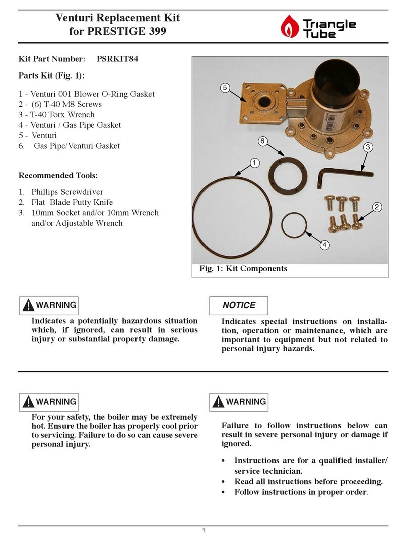
HMG Delta CLASSIC Replacement Kit
Electronic Spark Ignition
1
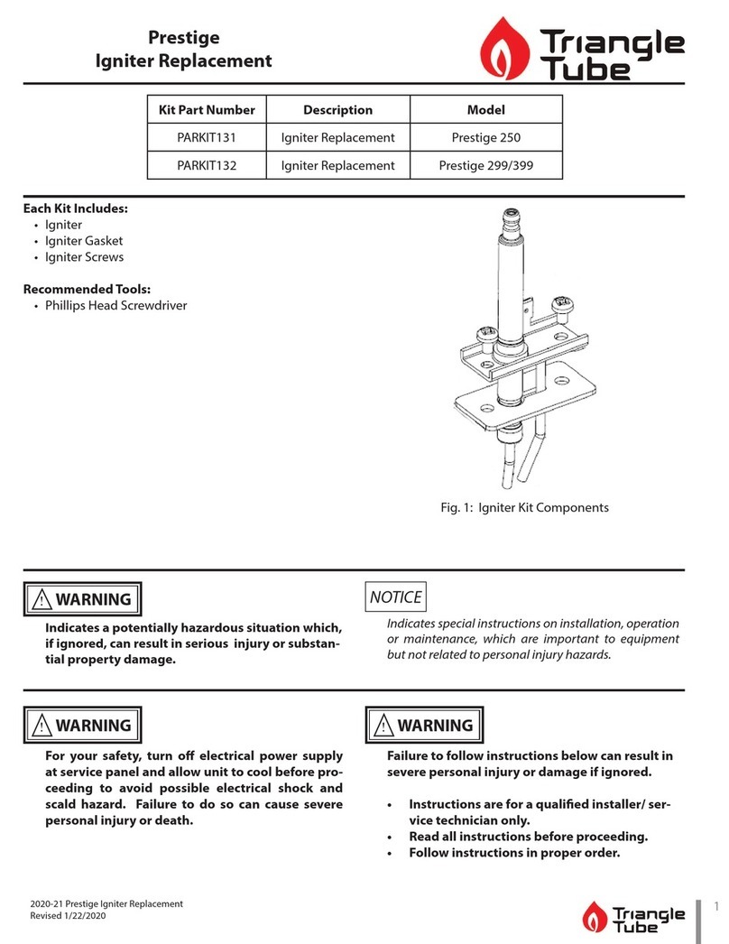
Kit Part Numbers: PGRKIT25
Parts List
1- Series 1 Pilot Hood/Bracket Assembly
2- Series 2 Pilot Hood Assembly
3- Ground Rod
4- Ground Rod Sleeve
5- Ground Rod Sleeve Retainer Nut
6- Electrode
7- Pilot Orifice
8- 3/4” Spacer
9- Machine Screw
10- Nut
11- 3/8” Spacer
12- Lock Washer
13- L-Key Wrench
14- Retaining Screw
Indicates a potentially hazardous situation
which, if ignored, can result in serious
injury or substantial property damage.
Indicates special instructions on installa-
tion, operation or maintenance, which are
important to equipment but not related to
personal injury hazards.
NOTICEWARNING
1
2
4
5
7
3
6
11
13
12
10 9
14
8
Failure to follow instructions below can result
in severe personal injury or damage if ignored.
• Instructions are for a qualified installer/ ser-
vice technician.
• Read all instructions before proceeding.
• Follow instructions in proper order.
For your safety, turn off electrical power
supply at service panel before proceeding to
avoid possible electrical shock hazard.
Failure to do so can cause severe personal
injury or death.
WARNINGWARNING
Identifying Pilot Assembly Series
If the pilot assembly is mounted on a vertical brack-
et which is attached to the burner neck, refer to
Series 1 Conversion instructions.
If the pilot assembly is mounted on a horizontal
bracket which is attached to the burner neck, refer
to Series 2 Conversion instructions.
HMG Delta CLASSIC Replacement Kit
Electronic Spark Ignition
2
Series 1 Pilot Assembly Instructions
Removal of the Burner and Existing Pilot
Assembly
1. Ensure power to the unit has been disconnected
prior to removal of the burner assembly.
2. Disconnect the snap-set plug located on the bot-
tom right side of the windbox. Depress the tab
and grip the body of the snap-set to prevent
damage to the incoming wire leads when dis-
connecting.
3. Lift and remove the air inlet tube from the
blower housing flange. If necessary, disconnect
any air inlet piping connected to the unit prior to
removing the air inlet tube.
4. Remove silicon tubing from the “v” (vaccum)
side of the pressure switch.
5. Disconnect the 24V supply to the control mod-
ule at the male to female connecters located on
the wires near the gas valve.
6. Turn the main manual gas shut-off valve at the
unit to the OFF position.
7. Disconnect the gas supply piping at the inlet of
the gas valve.
Failure to disconnect electrical supply and
close the gas shut-off valve can cause severe
personal injury, death or substantial proper-
ty damage.
8. Dismount and remove the burner assembly
from the unit by removing the (2) 17mm mount-
ing nuts located to the left and right side of the
windbox.
Care must be taken when removing the
burner assembly from the unit as not to dam-
age the mounting plate insulation or the pilot
assembly and pilot tube.
The service technician may need to remove
the burner control module from the top of the
windbox to allow ease of removing the burn-
er assembly from the combustion chamber
9. Disconnect the ignition cable from the pilot /
electrode assembly. Inspect the cable for any
damage, replace as needed.
8. Disconnect the pilot gas tubing from the pilot
assembly by loosening the compression fitting.
Use care not to damage the tubing, replace as
needed.
9. Remove the pilot assembly and bracket from the
vertical bracket by removing the (2) mounting
screws and nuts from the vertical support bracket.
Installation of New Pilot Assembly Components
1. Mount the new pilot hood / bracket assembly to
the vertical support on the burner neck using (2)
machine screws with lock washers and nuts.
NOTICE
WARNING
WARNING
HMG Delta CLASSIC Replacement Kit
Electronic Spark Ignition
3
2. Insert the pilot orifice into the pilot hood and
tighten with a wrench. No thread sealant is nec-
essary for the connection.
3. Insert the Grounding Rod through the bottom of
the Pilot Hood / Bracket Assembly. Attach the rod
clip onto the pilot hood / orifice to secure the rod.
4. Place the (3) 3/8” spacers over the Grounding
Rod.
5. Insert the Electrode through the Pilot Hood /
Bracket assembly and over the Grounding Rod.
Place the 3/4” spacer between the bracket
assembly and the ceramic body of the
Electrode.
6. To secure the Electrode into place tighten the
set screws onto the Grounding Rod using the L-
key supplied with the kit.
7. Reconnect the ignition cable to the pilot / elec-
trode assembly.
Inspect and ensure the ignition cable is free
of damage. Replace as needed.
8. Reconnect the pilot gas tubing to the pilot ori-
fice. Ensure the pilot tubing is tight and secure
Inspect and ensure the pilot gas tubing is free of
damage, breaks or kinks. Replace as needed.
9. Check the insulation gasket on the burner
mounting plate. Replace if damaged.
If the burner plate insulation is damage or
show signs of deteroration, replace the insu-
lation gasket. Failure to replace a damage
insulation gasket can cause flue gas leakage
for the burner assembly, resulting in severe
personal injury or death
10. Remount the burner assembly into the combus-
tion chamber. Use care not to damage the burn-
er mounting plate insulation, pilot gas tubing or
the spark ignition cable when inserting the
burner assembly into the combustion chamber.
Extreme care must be given when inserting
the burner assembly into the combustion
chamber to prevent damage to the insulation
gasket, pilot gas tubing and ignition cable.
11. Secure the burner assembly using the (2) 17mm
mounting nuts located to the left and right side
of the windbox.
12. Reconnect the gas supply piping to the gas
valve.
13. Re-seat the combustion air inlet tube onto the
blower flange. Reconnect the air inlet piping to
the unit as needed.
14. Reconnect the snap-set on the right side of the
windbox.
15. Open the main gas valve shut-off valve and per-
form a leak test at all gas piping connections
near the unit.
WARNING
WARNING
WARNING
WARNING
WARNING
HMG Delta CLASSIC Replacement Kit
Electronic Spark Ignition
4
Do not check for gas leaks with an open
flame. Use a gas detector or a bubble test.
Failure to check for gas leaks can cause
severe personal injury, death or severe prop-
erty damage.
16. Reconnect electrical power to the unit returning
the unit back into service.
Series 2 Pilot Assembly Instructions
Removal of the Burner and Existing Pilot
Assembly
1. Ensure power to the unit has been disconnected
prior to removal of the burner assembly.
2. Disconnect the snap-set plug located on the bot-
tom right side of the windbox. Depress the tab
and grip the body of the snap-set to prevent
damage to the incoming wire leads when dis-
connecting.
3. Lift and remove the air inlet tube from the
blower housing flange. If necessary, disconnect
any air inlet piping connected to the unit prior
to removing the air inlet tube.
4. Turn the main manual gas shut-off valve at the
unit to the OFF position.
5. Disconnect the gas supply piping at the inlet of
the gas valve.
Failure to disconnect electrical supply and
close the gas shut-off valve can cause severe
personal injury, death or substantial proper-
ty damage.
6. Dismount and remove the burner assembly
from the unit by removing the (2) 17mm
mounting nuts located to the left and right side
of the windbox.
Care must be taken when removing the
burner assembly from the unit as not to dam-
age the mounting plate insulation or the pilot
assembly and pilot tube.
The service technician may need to remove
the burner control module from the top of the
windbox to allow ease of removing the burn-
er assembly from the combustion chamber.
7. Disconnect the ignition cable from the pilot /
electrode assembly. Inspect the cable for any
damage, replace as needed.
8. Disconnect the pilot gas tubing from the pilot
assembly by loosening the compression fitting.
Use care not to damage the tubing.
9. Remove the Electrode from the mounting
bracket by loosening the setscrews on the
Ground Rod.
10. Remove the Ground Rod from the mounting
bracket by unclipping the retaining clip from
the Pilot Hood / Orifice.
11. Remove the Pilot Hood from the mounting
bracket by removing the retaining screw.
Installation of New Pilot Assembly Components
1. Thread the new Pilot Orifice into the new Pilot
Hood. No thread sealant is required.
2. Insert the Ground Rod Sleeve into the Pilot
Hood Assembly and secure with the Ground
Rod Sleeve Retainer Nut.
NOTICE
WARNING
WARNING
HMG Delta CLASSIC Replacement Kit
Electronic Spark Ignition
5
3. Insert the Ground Rod through the Ground Rod
Sleeve. Clip the retaining clip onto the Pilot
Hood / Orifice.
4. Place the (2) 3/8” spacers over the Grounding
Rod.
5. Insert the Electrode through the Burner bracket
and over the Grounding Rod. Place the 3/4”
spacer between the bracket assembly and the
ceramic body of the Electrode.
6. To secure the Electrode into place tighten the
set screws onto the Grounding Rod using the L-
key supplied with the kit.
7. Use the retaining screw to secure the Pilot Hood
assembly onto the mounting bracket.
8. Reconnect the ignition cable to the pilot /
eletrode assembly.
Inspect and ensure the ignition cable is free
of damage. Replace as needed.
9. Reconnect the pilot gas tubing to the pilot ori-
fice. Ensure the pilot tubing is tight and secure
Inspect and ensure the pilot gas tubing is free
of damage, breaks or kinks. Replace as
needed.
10. Check the insulation gasket on the burner
mounting plate. Replace if damaged.
If the burner plate insulation is damage or
show signs of deterioration, replace the insu-
lation gasket. Failure to replace a damage
insulation gasket can cause flue gas leakage
for the burner assembly, resulting in severe
personal injury or death
11. Remount the burner assembly into the combus-
tion chamber. Use care not to damage the burn-
er mounting plate insulation, pilot gas tubing or
the spark ignition cable when inserting the
burner assembly into the combustion chamber.
12. Secure the burner assembly using the (2) 17mm
mounting nuts located to the left and right side
of the windbox.
Extreme care must be given when inserting
the burner assembly into the combustion
chamber to prevent damage to the insulation
gasket, pilot gas tubing and ignition cable
13. Reconnect the gas supply piping to the gas
valve.
14. Re-seat the combustion air inlet tube onto the
blower flange. Reconnect the air inlet piping to
the unit as needed.
15. Reconnect the snap-set on the right side of the
windbox.
16. Open the main gas valve shut-off valve and per-
form a leak test at all gas piping connections
near the unit.
Do not check for gas leaks with an open
flame. Use a gas detector or a bubble test.
Failure to check for gas leaks can cause
severe personal injury, death or severe prop-
erty damage.
WARNING
WARNING
WARNING
WARNING
WARNING
HMG Delta CLASSIC Replacement Kit
Electronic Spark Ignition
62003-23 Pilot Replacement Kit
Revised 5/03
Fig. 2: Series 2 Pilot Assembly
A. Pilot Orifice
B. Pilot Hood Assembly (Series 2)
C. Ground Rod
D. Ground Rod Sleeve Retainer Nut
E. Ground Rod Sleeve
F. 3/8” Spacers (2 required)
Fig. 1: Series 1 Pilot Assembly
A. Pilot Hood / Bracket Assembly
B. Pilot Orifice
C. Ground Rod
D. 3/8” Spacers (3 required)
E. 3/4” Spacers
F. Electrode

Other TriangleTube Boiler Supplies manuals
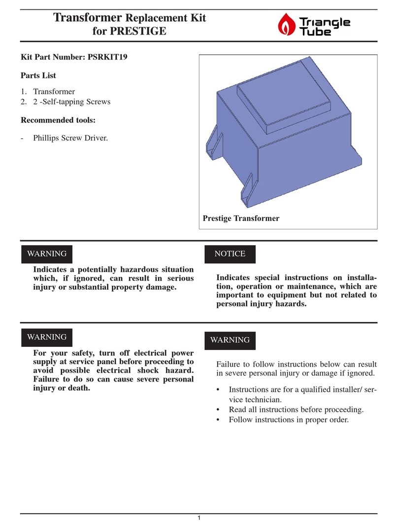
TriangleTube PSRKIT19 User manual

TriangleTube

TriangleTube PSRKIT19 User manual

TriangleTube PSRKIT53 User manual

TriangleTube

TriangleTube PSRKIT53 User manual

TriangleTube PARKIT131 Use and care manual

TriangleTube

TriangleTube PARKIT131 Use and care manual

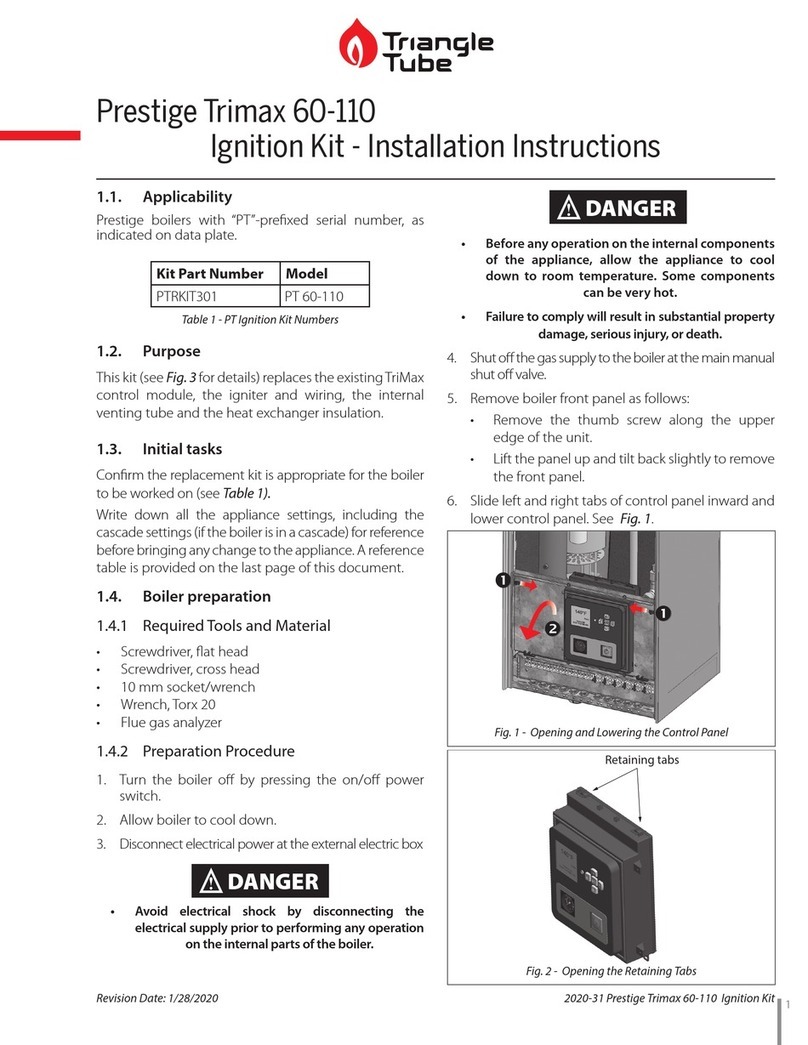
TriangleTube PTRKIT301 User manual

TriangleTube

TriangleTube PTRKIT301 User manual

TriangleTube PSRKIT44 User manual

TriangleTube

TriangleTube PSRKIT44 User manual

TriangleTube CHALLENGER CCRKIT38 User manual

TriangleTube

TriangleTube CHALLENGER CCRKIT38 User manual

TriangleTube PSRKIT36 User manual

TriangleTube

TriangleTube PSRKIT36 User manual

TriangleTube PTRKIT304 User manual

TriangleTube

TriangleTube PTRKIT304 User manual

TriangleTube PSRKIT80 User manual

TriangleTube

TriangleTube PSRKIT80 User manual
TriangleTube PSSTND02 User manual

TriangleTube

TriangleTube PSSTND02 User manual

TriangleTube PGRKIT30 User manual

TriangleTube

TriangleTube PGRKIT30 User manual

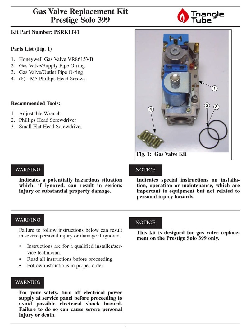
TriangleTube PSRKIT41 User manual

TriangleTube

TriangleTube PSRKIT41 User manual

TriangleTube CCRKIT32 User manual

TriangleTube

TriangleTube CCRKIT32 User manual

TriangleTube Instinct INSRKIT134 Use and care manual

TriangleTube

TriangleTube Instinct INSRKIT134 Use and care manual

TriangleTube Instinct SOLO 155-199 User manual

TriangleTube

TriangleTube Instinct SOLO 155-199 User manual

TriangleTube PSRKIT84 User manual

TriangleTube

TriangleTube PSRKIT84 User manual

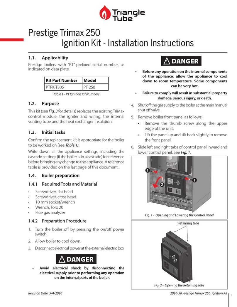
TriangleTube PTRKIT305 User manual

TriangleTube

TriangleTube PTRKIT305 User manual

TriangleTube PSRKIT51 User manual

TriangleTube

TriangleTube PSRKIT51 User manual
Popular Boiler Supplies manuals by other brands

Grant SpiraVac WPVKIT5POD Installation & user's instructions

Grant

Grant SpiraVac WPVKIT5POD Installation & user's instructions

Vaillant 0020230734 operating instructions

Vaillant

Vaillant 0020230734 operating instructions

ACV Prestige 85 Technical note

ACV

ACV Prestige 85 Technical note

Buderus GB162 installation instructions

Buderus

Buderus GB162 installation instructions

AFRISO WMS-WP6 operating instructions

AFRISO

AFRISO WMS-WP6 operating instructions

Immergas 3.030323 quick start guide

Immergas

Immergas 3.030323 quick start guide

IDEAL EXRKIT07 instructions

IDEAL

IDEAL EXRKIT07 instructions

Immergas VICTRIX SUPERIOR KIT quick start guide

Immergas

Immergas VICTRIX SUPERIOR KIT quick start guide

JJM Boiler Works JM-2 Installation operation & maintenance

JJM Boiler Works

JJM Boiler Works JM-2 Installation operation & maintenance

Navien G 002212 Series installation instructions

Navien

Navien G 002212 Series installation instructions

manuals.online logo
manuals.online logoBrands
  • About & Mission
  • Contact us
  • Privacy Policy
  • Terms and Conditions

Copyright 2025 Manuals.Online. All Rights Reserved.