manuals.online logo
Brands
  1. Home
  2. •
  3. Brands
  4. •
  5. TriangleTube
  6. •
  7. Boiler Supplies
  8. •
  9. TriangleTube PSRKIT80 User manual

TriangleTube PSRKIT80 User manual

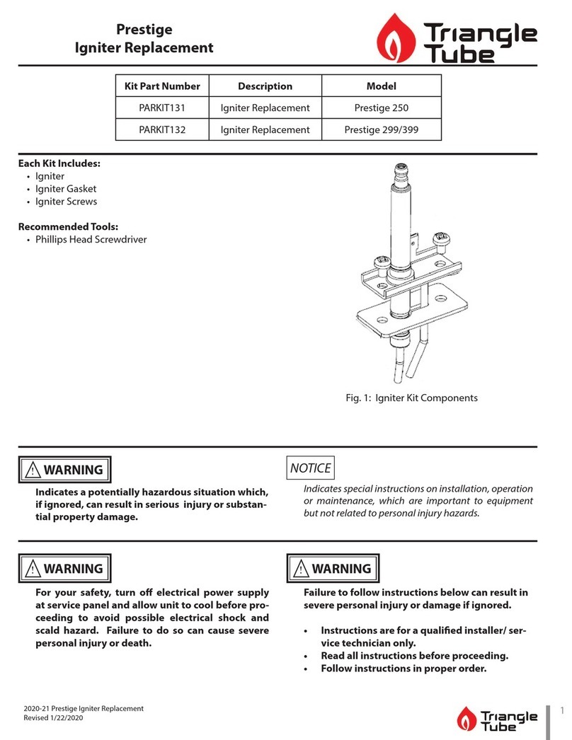
PRESTIGE Venturi
Replacement Kit
1
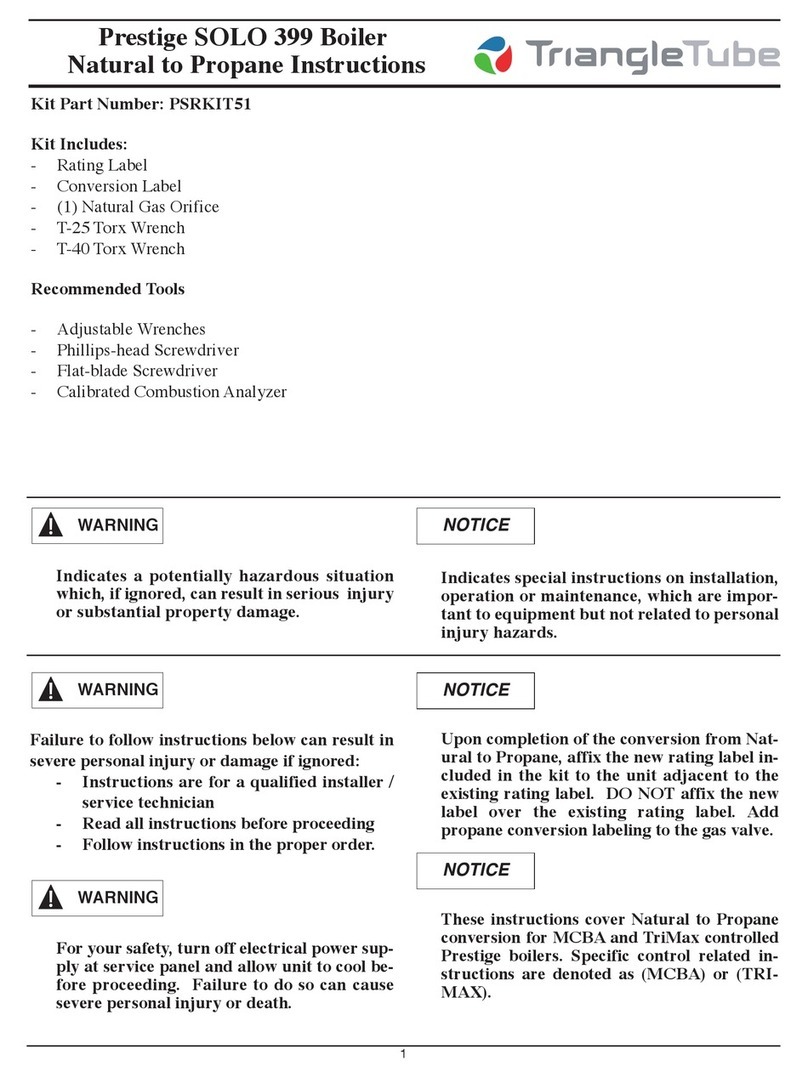
Kit Part Number:
PSRKIT80 (PS 60)
PSRKIT81 (PS 110 / PE 110)
PSRKIT82 (PS 175)
PSRKIT83 (PS 250)
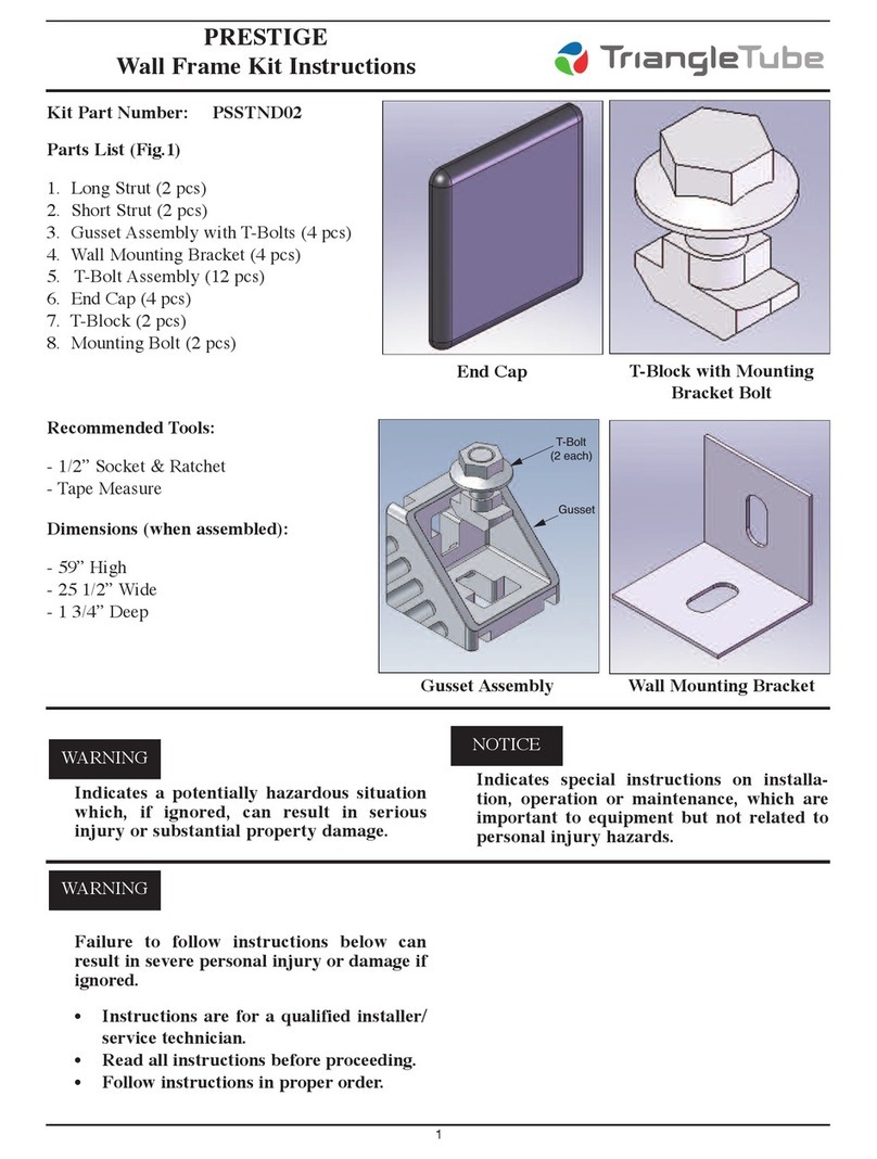
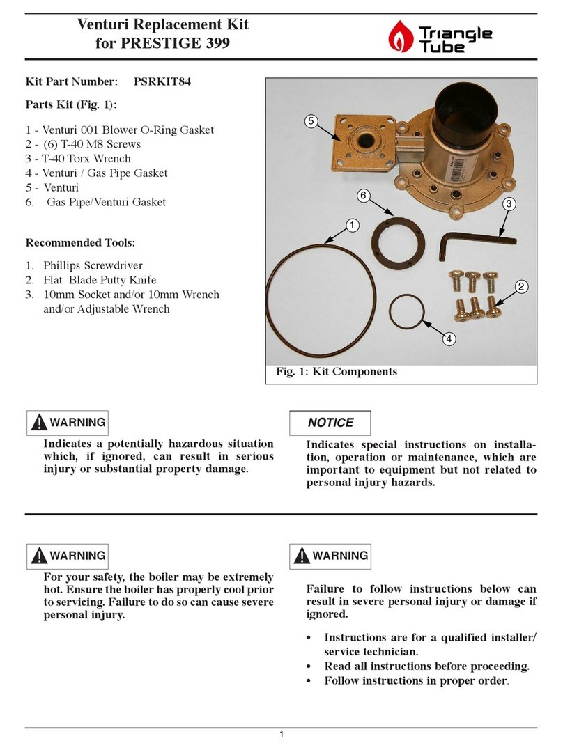
Parts List (Fig.1)
1 - Venturi ounting Gasket
2 - #25 Torx Wrench (not shown)
3 - (2) 5 x 12 Screws
4 - Venturi
Recommended Tools:
- Phillips Screwdriver
- Flat Blade Putty Knife
Indicates a potentially hazardous situation
which, if ignored, can result in serious
injury or substantial property damage.
For your safety, turn off electrical power
supply at service panel before proceeding to
avoid possible electrical shock hazard.
Failure to do so can cause severe personal
injury or death.
For your safety, the boiler may be extremely
hot. Ensure the boiler has properly cool prior
to servicing. Failure to do so can cause severe
personal injury.
Indicates special instructions on installa-
tion, operation or maintenance, which are
important to equipment but not related to
personal injury hazards.
Failure to follow instructions below can
result in severe personal injury or damage if
ignored.
• Instructions are for a qualified installer/
service technician.
• Read all instructions before proceeding.
• Follow instructions in proper order.
For appropriate venturi size to PRESTIGE
Model, Reference Table 1 on page 3. The
venturi size is listed on the label affixed to
the venturi and is imprinted on the black
venturi cone.
WARNING
WARNING
WARNING
WARNING
NOTICE
NOTICE
3
4
1
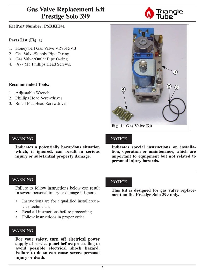
Fig. 1: Kit Components
PRESTIGE Venturi
Replacement Kit
Instructions
1. Turn power to the unit “OFF”.
2. Remove the front jacket panel. Swing away the
Control odule panel ( CBA) or tilt down the
Control odule panel (Tri ax).
3. Shut off gas supply to the Prestige boiler at the
main manual shutoff valve.
4. Disconnect the gas piping at the brass union
located near the gas valve inside the boiler
enclosure.
5. Using a Phillips screwdriver disconnect the rec-
tifier cable to the gas valve ( CBA).
6. Remove olex plug from gas valve (Tri ax).
7. Remove the air inlet elbow from the venturi.
Note the orientation of the venturi / gas valve
assembly and the venturi gasket in relation
to the blower housing when disassembling
the venturi / gas valve assembly.
8. Using the #25 Torx wrench from the kit remove
the 2 venturi mounting screws attaching the
venturi / gas valve assembly to the blower, see
Fig. 2. Remove the venturi / gas valve assem-
bly from the blower.
There is a gasket between the venturi and the
blower housing. If the gasket “sticks” to the
blower housing use a flat blade putty knife to
remove any gasket material. Make sure not
to scratch or score the mating surface on the
blower housing.
9. Remove the three screws attaching the gas valve
to the venturi as shown in Fig. 3. Use Torx
wrench supplied in kit to remove screws. Note
orientation of the venturi to the old gas valve for
reassembly of the new venturi on the gas valve.
10. Reassemble the gas valve, using the existing three
Torx screws to the venturi. See Fig. 3.
Ensure the gas valve/orifice gasket is in place
before reassembling the gas valve and venturi.
Failure to do so can result in death, serious
injury or substantial property damage.
For propane installations a brass orifice is
located inside the gas valve/orifice gasket.
This orifice must be placed inside of the new
gas valve/orifice gasket before reassembly.
Failure to insert the propane brass orifice, on
propane installations, before reassembling
the gas valve and venturi can result in the
production of carbon monoxide due to
incomplete combustion and may result in
death, serious injury or substantial property
damage.
NOTICE
NOTICE
WARNING
NOTICE
WARNING
2
Venturi/Gas
Valve Assembly
Venturi
Mounting Screw
Venturi
Mounting Screw
Fig. 2: Venturi/Gas Valve Assembly
PRESTIGE Venturi
Replacement Kit
3
For the reassembly process do not use adhe-
sive on any gasket surface.
11. Install the venturi gasket on the venturi and
reassemble the venturi / gas valve assembly to
the blower housing using the (2) 5 x 12
mounting screws supplied in the kit. Use the
#25 Torx wrench to tighten all screws and
secure the assembly.
12. Reconnect the rectifier plug to the gas valve
using the Phillips head screw ( CBA).
13. Reconnect olex plug to the gas valve
(Tri ax).
14. Reconnect the brass gas piping union connec-
tion. Open the main manual gas shutoff valve
before placing the PRESTIGE unit back into
operation check and test all gas connections for
leaks. Repair leaks if found.
Do not check for gas leaks with an open flame.
Use a bubble test. Failure to check for gas
leaks can cause severe personal injury, death
or substantial property damage.
15. Reattach the air inlet elbow to the venturi.
16. Reposition the Control odule panel and reat-
tach the front jacket panel.
17. Turn the electrical power “ON” to the PRES-
TIGE to return the unit back into service.
C MBUSTI N TEST/ADJUSTEMENT
It is recommended that the installer perform a com-
plete combustion check to ensure the following
combustion levels are met at high and low inputs
and the burner is operating at optimum conditions.
NOTICE
WARNING
Gas Valve
Blower
Venturi / Blower Gasket
Venturi
Fig. 3: Venturi Assembly
PRESTIGE
odel
Venturi
Size
PS 60 055
PS 110 002
PE 110
PS 175 052
PS 250 051
Table 1: Venturi Sizes
Natural Gas Propane
O2 Min. 2.30% 2.70%
O2 Max. 5.30% 4.70%
CO2 Min. 8.80% 10.70%
CO2 Max. 10.50% 12.00%
CO Max. 100 ppm 100 ppm
Table 2: Recommended Combustion Levels
PRESTIGE Venturi
Replacement Kit
4
The combustion testing and adjustments
must be performed by a qualified installer,
service agency or the gas supplier. All com-
bustion measurements must be perform with
calibrated equipment to ensure proper read-
ings and accuracy.
Failure to perform a complete combustion
test at both high and low input rates may
result in incomplete combustion and the pro-
duction of carbon monoxide, which can
cause severe personal injury, death or sub-
stantial property damage.
MCBA Instructions
1. anually place the boiler into High fire mode
by pressing the ODE button with “+” button
simultaneously on the control panel display
while in the standby (STBY) mode.
The control panel will display a H followed
by the current boiler temperature when
placed into high fire test mode.
2. If the combustion levels during High fire are
outside the recommended combustion settings
adjust the THROTTLE SCREW (see Fig. 4) as
follows:
Counter-clockwise adjustment of the THR T-
TLE SCREW at high fire:
O2decreases and C02increases
Clockwise adjustment of the THR TTLE
SCREW at high fire:
O2increases and CO2decreases
3. Once the combustion level is set at High fire,
manually place the boiler into Low fire mode by
pressing the ODE button with “-” button
simultaneously on the control display while in
the standby (STBY) mode.
The control panel will display a L followed
by the current boiler temperature when
placed into low fire test mode.
4. If the combustion level at Low fire is not with-
in +/- 0.2% of the combustion level measured at
High fire, remove the offset cover screw and
adjust the plastic FFSET SCREW using a T-
40 Torx wrench (see Fig. 4) as follows:
Counter-clockwise adjustment of FFSET
SCREW at low fire:
O2increases and CO2decreases
Clockwise adjustment of FFSET SCREW at
low fire:
O2decreases and CO2increases
5. Press the “+” and “-” buttons simultaneously to
shutdown the burner.
WARNING
NOTICE
NOTICE
WARNING
Offset Pressure
Cover Screw
Throttle
Screw
Fig. 4: Combustion Adjustment - Prestige Burner
PRESTIGE Venturi
Replacement Kit
5
Revised Date: 5/30/12 2011-51 Prestige Venturi Replacement Kit_1111
Trimax Instuctions
1. Press the round INSTALLER button. See Fig. 5.
2. Enter the installer access code “054” by using
the LEFT and RIGHT buttons to select a digit
and the UP and D WN buttons to change the
digit. Press the K button to enter the access
code.
3. Press the RIGHT button to highlight the
anual Operation icon then press the K
button.
4. Press the K button while the FAN icon is
highlighted to manually fire the burner and
power the CH circulator.
An adequate CH load must be present to dissi-
pate the heat generated during the combustion
test. If an adequate CH load is not available, an
indirect water heater can be used to dissipate the
heat by creating a DHW call which will enable
the DHW circulator.
5. Press the RIGHT button to adjust the firing rate
to 100%. Hold down the RIGHT button to
rapidly increase the firing rate.
6. If the combustion levels during High fire are
outside the recommended combustion settings
adjust the THROTTLE SCREW (see Fig. 4) as
follows:
Counter-clockwise adjustment of the THR T-
TLE SCREW at high fire:
O2decreases and C02increases
Clockwise adjustment of the THR TTLE
SCREW at high fire:
O2increases and CO2decreases
7. Once the combustion level is set at High fire,
manually place the boiler into Low fire mode by
pressing the LEFT button to adjust firing rate
down to 0%.
8. If the combustion level during Low fire is not
within +/-0.2 of the combustion level measured
at High fire, remove the offset cover screw and
adjust the plastic OFFSET SCREW (see Fig. 4)
using a T-40 Torx wrench as follows:
Counter-clockwise adjustment of FFSET
SCREW at low fire (0% firing rate):
O2increases and CO2decreases
Clockwise adjustment of FFSET SCREW at
low fire (0% firing rate):
O2decreases and CO2increases
9. Press the K button while the fan icon is high-
lighted to shutdown the burner.
10. Press the LEFT or RIGHT button to highlight
the home screen icon to exit the service
mode.
NOTICE
Installer
Button
Fig. 5: Trimax Navigation Buttons
Manual Operation
Released
O
O
O
CH
CH1
FAN
DHW
SYS
CH2

This manual suits for next models

3

Other TriangleTube Boiler Supplies manuals
TriangleTube PARKIT131 Use and care manual

TriangleTube

TriangleTube PARKIT131 Use and care manual

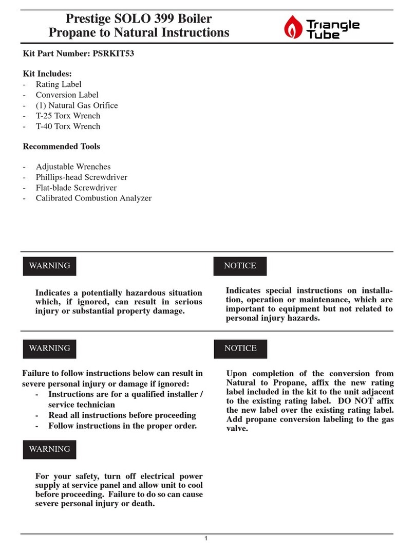
TriangleTube PSRKIT53 User manual

TriangleTube

TriangleTube PSRKIT53 User manual

TriangleTube PSRKIT41 User manual

TriangleTube

TriangleTube PSRKIT41 User manual

TriangleTube PSRKIT44 User manual

TriangleTube

TriangleTube PSRKIT44 User manual

TriangleTube PGRKIT25 User manual

TriangleTube

TriangleTube PGRKIT25 User manual
TriangleTube PTRKIT305 User manual

TriangleTube

TriangleTube PTRKIT305 User manual

TriangleTube PGRKIT30 User manual

TriangleTube

TriangleTube PGRKIT30 User manual
TriangleTube CHALLENGER CCRKIT38 User manual

TriangleTube

TriangleTube CHALLENGER CCRKIT38 User manual

TriangleTube Instinct SOLO 155-199 User manual

TriangleTube

TriangleTube Instinct SOLO 155-199 User manual

TriangleTube PSRKIT19 User manual

TriangleTube

TriangleTube PSRKIT19 User manual

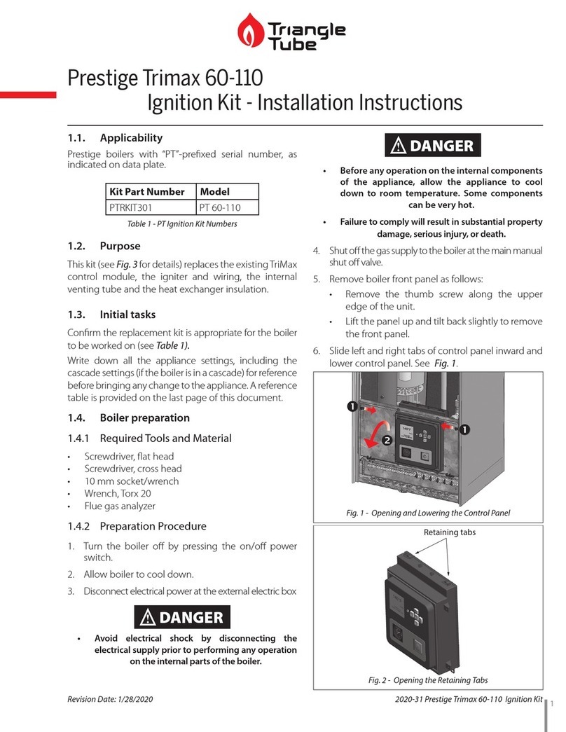
TriangleTube PTRKIT301 User manual

TriangleTube

TriangleTube PTRKIT301 User manual

TriangleTube PSRKIT84 User manual

TriangleTube

TriangleTube PSRKIT84 User manual

TriangleTube PSSTND02 User manual

TriangleTube

TriangleTube PSSTND02 User manual

TriangleTube CCRKIT32 User manual

TriangleTube

TriangleTube CCRKIT32 User manual

TriangleTube PSRKIT36 User manual

TriangleTube

TriangleTube PSRKIT36 User manual

TriangleTube Instinct INSRKIT134 Use and care manual
TriangleTube

TriangleTube Instinct INSRKIT134 Use and care manual

TriangleTube PSRKIT51 User manual

TriangleTube

TriangleTube PSRKIT51 User manual

TriangleTube PTRKIT304 User manual

TriangleTube

TriangleTube PTRKIT304 User manual
Popular Boiler Supplies manuals by other brands

IDEAL EXRKIT08 instructions

IDEAL

IDEAL EXRKIT08 instructions

Immergas 3.031186 Instruction and warning book

Immergas

Immergas 3.031186 Instruction and warning book

Tucson GBPHR/8/CCW Installation, operation and maintenance manual

Tucson

Tucson GBPHR/8/CCW Installation, operation and maintenance manual

Grant SpiraPod installation instructions

Grant

Grant SpiraPod installation instructions

Miura WP2-200A installation manual

Miura

Miura WP2-200A installation manual

REMEHA Rematic 2945 C3K+ Assembly instructions

REMEHA

REMEHA Rematic 2945 C3K+ Assembly instructions

Immergas 3.030323 quick start guide

Immergas

Immergas 3.030323 quick start guide

Beretta 20067668 instruction manual

Beretta

Beretta 20067668 instruction manual

REMEHA Rematic 142 Assembly instructions

REMEHA

REMEHA Rematic 142 Assembly instructions

Navien G 002212 Series installation instructions

Navien

Navien G 002212 Series installation instructions

manuals.online logo
manuals.online logoBrands
  • About & Mission
  • Contact us
  • Privacy Policy
  • Terms and Conditions

Copyright 2025 Manuals.Online. All Rights Reserved.