TRONXY X5SA-500-PRO User manual


Thank you for choosing TRONXY products!
We will serve you whole heartedly!
Please read the instruction carefully
Please visit tronxy.com for more information
TEL:+86-755-89968500
Relevant information is stored in
SD card,please check

After- sale service:support@tronxy.com
Service nach dem Verkauf: support@tronxy.com
アフターサービス:support@tronxy.com
Послепродажное обслуживание: support@tronxy.com
Facebook QR CodeX5SA-500Pro Install
video QR Code
Aftersale contact
QR Code
Servicio postventa: support@tronxy.com
Serviço pós-venda: support@tronxy.com
판매 후 서비스 : support@tronxy.com
بع دعيبلا :support@tronxy.com
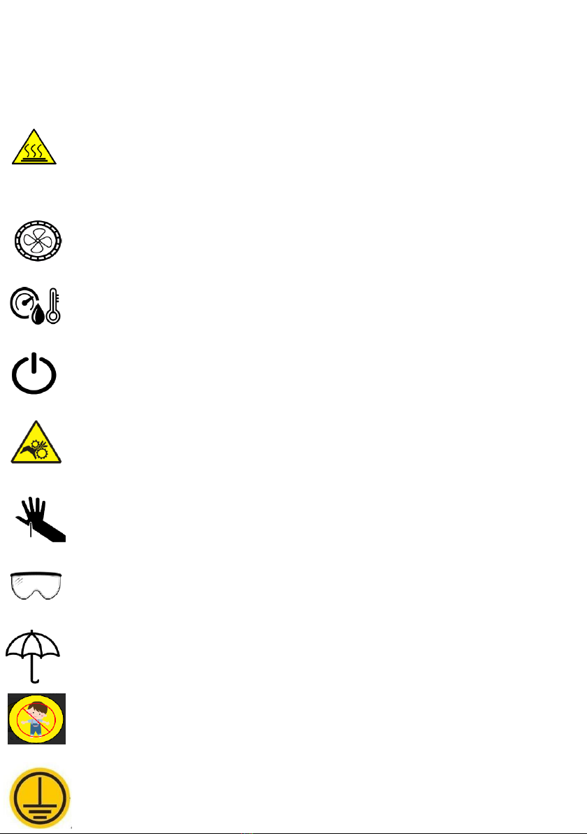
Pay attention
Please read this instruction carefully and follow the
safety instruction.
When the 3D printer is working, it will produce high temperature.Do not
touch working parts or extruder directly.After printing, the working part
may still be in the high temperature state.Please wait patiently for the
working parts and the print model to cool down before removing the model
from the print platform.
Please use the 3D printer in a spacious and well-ventilated
environment.
The recommended ambient temperature for 3D printers is
8°C-40°C, and the humidity is 20%-80%. Using outside this
range may bring bad printing effects.
In case of emergency, could turn off the power of the
3D printer directly.
3D printers contain working parts that move at high
speeds, so be wary of pinching your hands.
When removing the model from the print platform, be careful
not to swipe sharp objects at your finger.
Assemble the 3D printer or polish the model. suggest Wear
goggles.
Please pay attention to the protection of 3D printer
against rain and moisture.
Keep children away from the machine when it running
It is not recommended to run a 3D printer when left
unattended.
Use wires must be connected to the earth

Catalogue
1. Machine parameter ………………………………………1
2. Introduction to machine structure …………………2
3. Packing list ……………………………………………………3
4. Installation instructions …………………………………4
5. Interface operation and printing …………………17
6. Slice software ………………………………………………20
7. Fault cause analysis ………………………………………23

Print parameters
Print principle
: FDM (Fused deposition molding)
Print size
: 500×500×600 (mm3)
Print accuracy
: 0.1-0.4 mm
Positioning accuracy
:X/Y0.00625mm,Z 0.0125mm
Nozzle quantity
: 1
Nozzle size
: 0.4 mm
Print speed
: 20~100mm/s (suggest 60mm/s)
Moving speed
: 100mm/s
Filament
: PLA, TPU, ABS, wood etc.
Temperature parameters
Environmental temp:
8°C - 40°C
Nozzle temp:
Max260℃
Heat bed temp:
support
Software
Slice software:
Cura
Input format:
.STL .OBJ
Output format:
GCode
Connection:
TF card, USB cable(Suitable for skilled users
)
Power supply
Power input:
110V/220V AC, 50/60Hz
Power output
:24V/21A DC
Physical parameter
Machine size:
810mm×812mm×915mm
Machine weight:
~28.5kg
1. Machine parameter
1
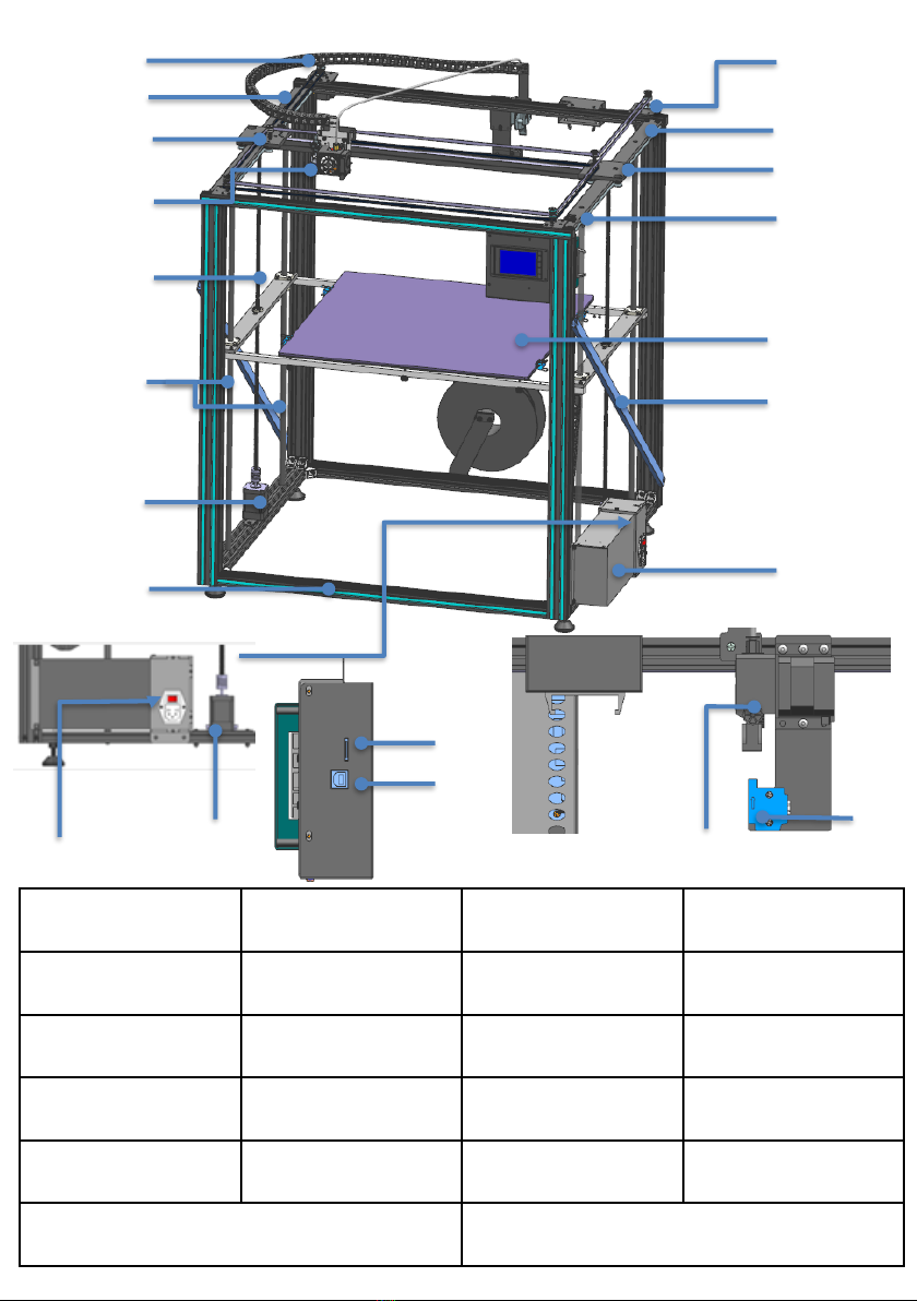
2. Introduction to machine structure
④
⑤
①
②
③
⑥
⑦
⑧
⑨
⑩
⑪
⑫
⑬
⑮
⑭
⑯⑰
⑱
⑲
⑳㉑
2
1.Power Supply 2.Stainless steel pipe 3.Heatbed 4.Y axis switch
6.Y-right guide rail
5.Y- right skateboard 7.Xmotor
9. Y-left guide rail 10.Y- right skateboard 11. extruder head
13.lead screw
12.polish rod
14.Z2motor 16.power switch
17.Z1motor 18.TF interface 19.USB interface
15.aluminum frame
20.Titan extruder
21.filament run-out detection
8.Ymotor
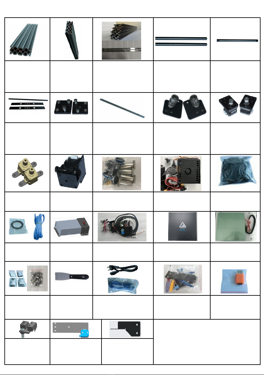
3. Packing list
2
040
aluminum
profile
630mm 2PCS
660mm 2PCS
2020aluminum
profile
740mm 2PCS
4040aluminum profile
780mm 4PCS
Stainless steel pole
2PCS
OSG External double
axis guide rail
-Y
axis
670mm 2PCS
OSG External double
axis guide rail
-X
axis
650mm 1PCS
beams/footlock
2pcs
left and right
sliding parts
polished rod
760MM 4PCS
lead screws
665MM 2PCS
left /right belt pulley
parts X/Y axis motors
Zaxis motor
parts
Titan extruder
component bag
controller + touch
screen belt bag
filament
+seal
(
Color random
)
Power Supply
print head
aluminum plate with
balck sticker heat bed
screws bag 4PCS
Corner code bag
1PCS
shovel
(
Color
random)
USB cable+ power line
Tools bag reader+TFcard
Yswitch parts
1PCS
filament run out
detection parts
1PCS
Double limit plate
2pcs
3
After receiving the goods, please
check the accessories according to
the packing list. If you have any
questions, please contact customer
service.

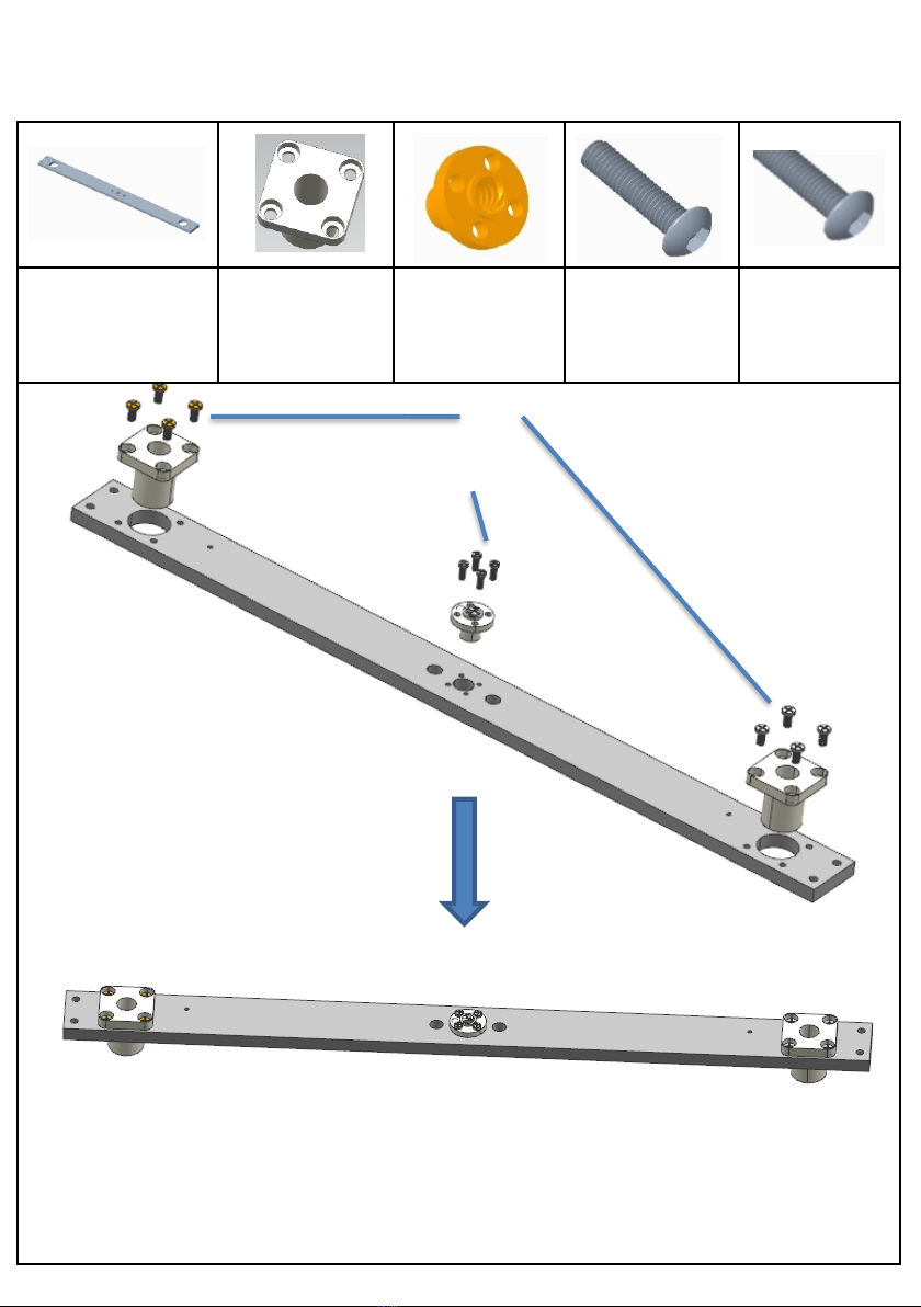
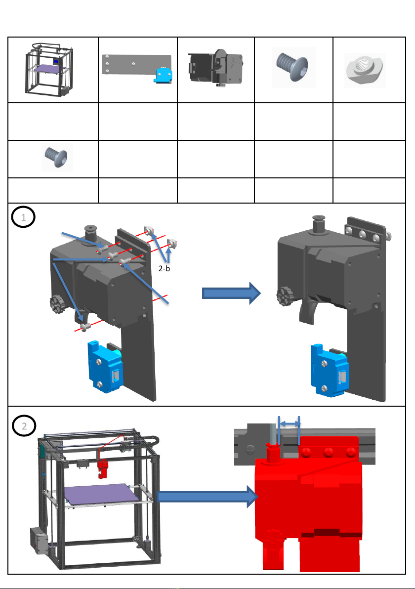
4. Installation instructions
Step 1:base frame assembly
Assembly material specification and quantity
:
aluminum1
40*40*780 4PCS
aluminum2
40*20*660 2PCS
aluminum3
40*20*630 2PCS
Corner code
20PCS
screws M4*8
40PCS
gasket M4
40PCS
boat nuts M4
40PCS
screws M5*45
8PCS
12-aluminum1
4
1-aluminum2
M5*45
M5*45
2-aluminum3
Four countersunk
holes facing upward
on the surface
M4*8 M4 gasket boat nuts
Corner codes can be installed with
20 standby codes at a time
32-aluminum1
M5*45
M5*45
2
Note:
Installation
corner codes
should be kept
parallel and
vertical between
each aluminium
profile without
clearance.
Adjustment of
M5*45 can be
loosened slightly
before locking.
Slightly lock M5*45 screw for
easy follow-up adjustment
M6 threaded
hole Upward
M6 threaded hole
Upward
M6 threaded
hole Upward
M6 threaded hole
Upward
Installation corner codes in the connection of aluminium
profiles, it is necessary to keep the vertical and parallel
locking angle codes between the various aluminium
profiles.
The first step is to install the frame. After the
installation, the frame is assembled with the
second step, as shown in the figure.

Assembly material specification and quantity
:
base frame
1pcs
aluminum4
20*20*740 2PCS
L skateboard 1PCS
Y left guide 1PCS
R
skateboard
1PCS
Y right guide 1PCS
screwsM6*25
16PCS
Step 2: Sliding plate assembly
Take out the Y-axis guide rail and penetrate into
the left component and the right component of
the slide, respectively, as shown in the figure.
1The screw M6*25 is slightly locked on the Y-axis
guide rail to facilitate subsequent adjustment.
Direction Reference
Point for Installation
of Guideway
5
2aluminum
4
8-M6*25
Note: The installation position of Aluminum
Profile 4 and the bottom Aluminum Profile 3 (with
countersunk head holes) are in the vertical
direction. Do not misfit them.
2
Note: The left and right skateboards
penetrate the guide rail.
Please install in the right direction
according to the drawing.
(Refer to Y-axis guideway bag
Letters, L to L, R to R)
38-M6*25
When installing Y-axis guide to the frame, please
note that M4 screw holes are in the same direction,
and use this to determine the front of the 3D printer.
M4 screw
hole
Aluminum profile 4 aligns bottom frame, slightly
locking M6*25 screw, no locking is needed to
facilitate subsequent adjustment and installation.
Assembly material specification and quantity
:
basic frame 1pcs
X axis guide rail parts
20*18*650 1PCS
Print head parts
1pcs
drag chain plate
1pcs
screws
M4*20 6PCS
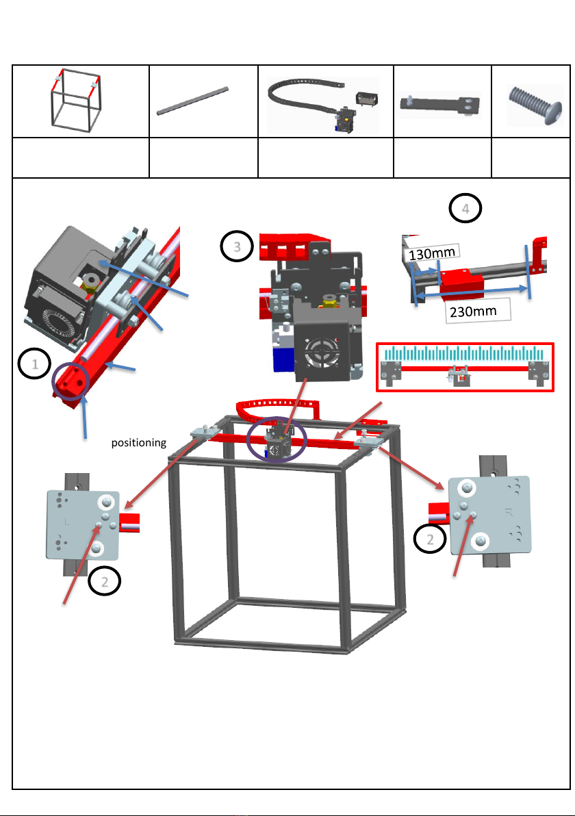
Step 3: Sliding plate assembly
1
pulley
X axis guide rail
M4 screws holes positioning
print head
3-M4*20
3-M4*20
2
2
3
4
6
1.Insert the print head into the X-axis guide rail, pay attention to the direction of the M4 screw hole, as
shown in Figure 1.
2. Insert the X-axis rail assembly into the alignment hole of the chassis, and tighten the screw
RM4*20 without locking it, as shown in Figure 2.
3. Move the left and right sliders to confirm that the X-axis rail assembly moves flexibly after locking
the RM4*20 screw.
4. After adjustment, lock the screw of RM5*25 on the Y-axis guide and move the X-axis guide assembly
again. Repeat the adjustment to ensure that the slide is flexible and has no gap after the locking screw.
As shown in the figure, the pulley on the print head
runs through the X axis guide rail and the slide
block moves smoothly without any clearance
The skateboard is in line with
the X-axis guide
Assembly material specification and quantity
:
basic frame parts
1pcs
right wheel parts
1pcs
left wheel parts
1pcs
X motor
1pcs
Y motor
1pcs
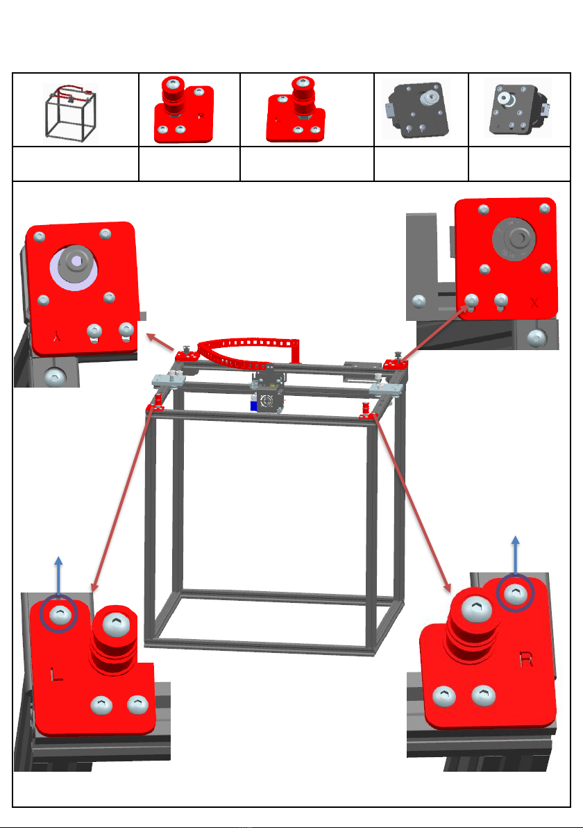
Step 4:XY axis motors and wheels assembly
7
This screw
positioning
Don't need to
tighten M4*16
This screw
positioning
Don't need
to tighten
M4*16
1. Lock and fix the assembled parts in the
position as shown in the figure
Assembly tips for M4 ship nut: first
align the M4 nut with the aluminum
profile slot, put it into the aluminum
profile slot, use a screwdriver to
reverse loosen, release the M4 ship
nut over the aluminum profile slot,
and then tighten it forward
Assembly material specification and quantity
:
basic frame
1pcs
Belt
2pcs Ties
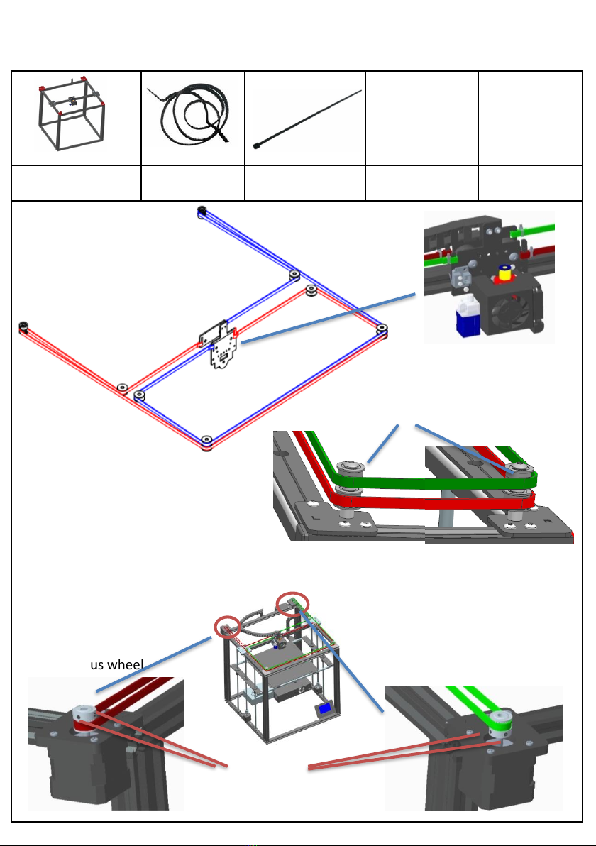
Step 5:Belts assembly
4-M3*3
8
Synchronous wheel
Synchronous wheel
Note: When the machine prints normally
after assembly.If the belt is too loud when
moving,The height of the left and right
wheel assembly can be adjusted by
increasing and reducing the gaskets.
During the printing process, the leather belt
has a slight sound, which is normal.
Left and right wheels
Belt tying diagram
X motor
Y motor
1.As shown in the figure, after
adjusting the distance between
the motor gear and the belt, lock
the 2 rice screws on the gear.
2. Also assemble the second belt,
the tension of the second belt
should be equal.
Note: Synchronization wheels on X, Y axis motors
Height should be adjusted by itself.
Be sure to install the belt
Each belt is on the same planeUp.
Location of Print Head Band
Assembly material specification and quantity
:
beams
2pcs
Linear bearing
4pcs
copper linear
bearing
2pcs
screws M4*12
16pcs
screws M3*8
8pcs
Step 6:Linear bearing assembly
16-M4*12
9
8-M3*8

Assembly material specification and quantity
:
basic frame
1pcs
Z axis motor parts
2pcs
foot lock parts
2pcs
bearing base parts
2pcs
polish rod
Φ8*760 4PCS
lead screwT8*665
2PCS
screws M4*30
8PCS
screws M4*8
4PCS
screws M4*16
4PCS
Step 7:Z axis parts assembly
4-M4*8
2-M3*3
4-M4*4
4-M4*30
M3 hole is inside.
1
2
3
10
polish
rod
polish
rod
lead screw
bearing base parts
As shown in Figure 1, assemble the assembly, put
the assembly into the frame as shown in Figure 2,
and align the holes to lock the screws.
Adjust the verticality of the polished
rod and tighten the screws
Shim
4-M4*30
M4 nut
4-M4*16
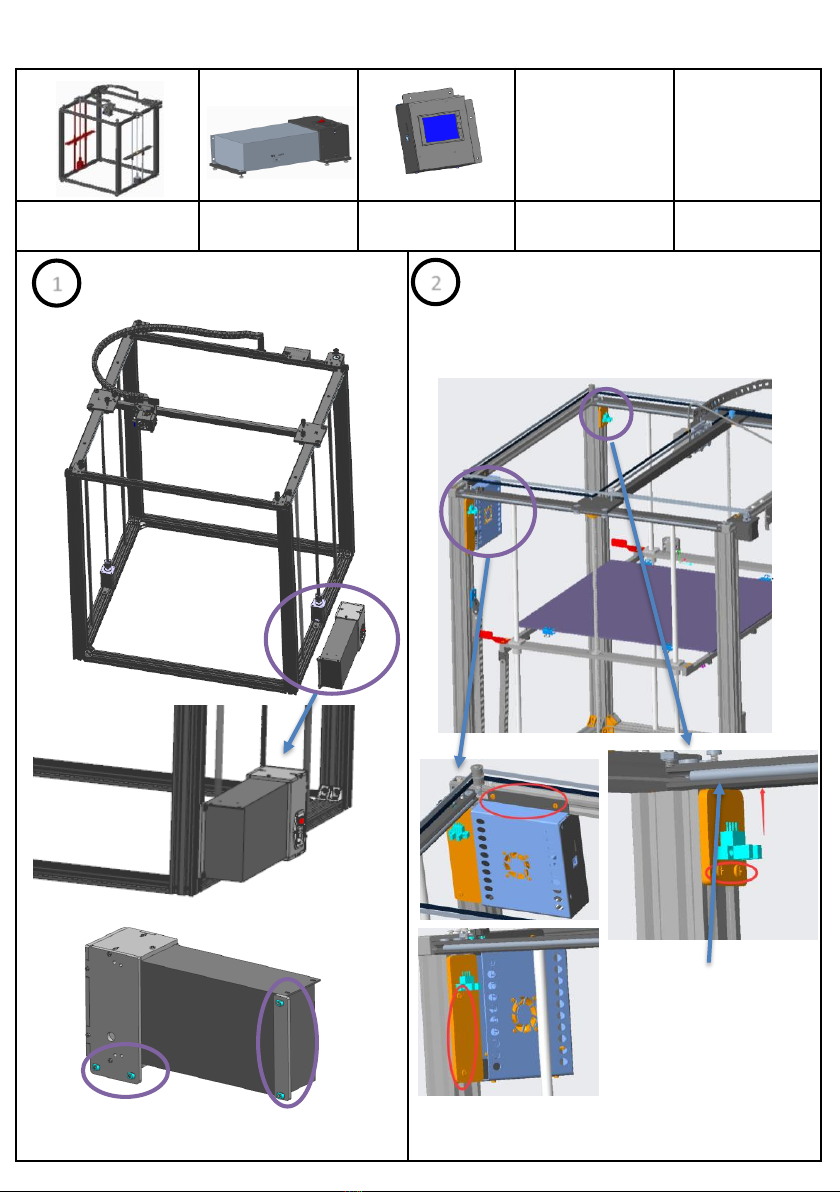
Assembly material specification and quantity
:
basic frame
1PCS
Power Supply
1PCS
controller box
1PCS
Step 8:Controller box assembly
1Install the power supply in the
lower right corner of the front of
the printer
2
boat nuts
11
boat nuts
Align
Install the main control box on the right
(facing the machine) profile (including a
photoelectric switch), and the other
photoelectric switch is fixed on the left
profile

Assembly material specification and quantity
:
basic frame
1pcs
heat bed parts
1pcs
beams
2pcs
plastic nuts M3
6pcs
screws M4*12
8pcs
spring
6pcs
nuts M3
6pcs
screws KM3*30
6pcs
Double limit
plate 2pcs
Step 9:Print plate assembly
1
4pcs hole position
6-KM3*30
6-spring
6-M3nuts
≈10mm
Move the left and right transverse plates on the
same plane. Lock the hot bed assembly on the
transverse plate according to Figure 2, and fix the
tow chain bracket according to Figure 3.
Rotate the screw, synchronize the moving platform
up and down, confirm the flexible movement,
need to adjust the screw PM4*12 and light rod and
motor screw.
beams
12
2-boat nuts+2-M4*8
2-M4*8
Hot bed drag chain
8-M4*12
3
2
Double
limit
plate
Assembly material specification and quantity
:
basic frame
1pcs
filament run out
detection parts
1pcs
Titan extruder
1pcs
screw RM4*8
2pcs
boat nuts
M4
2pcs
screw RM4*6
2pcs
Step 10:Feeding motor assembly
1
2-RM4*6 2-boat nuts
2
13
RM4*8
RM4*8
10MM
Assemble Titan extruder to filament runout detection parts
As shown, lock the Titan extruder assembly to the basic frame

Assembly material specification and quantity
:
printer
1PCS
Y switch parts
1PCS
bracket part
1PCS
screw
PM5*10
screwRM4*6
4PCS
boat nuts M4
2PCS
Step 11:Switch and filament bracket assembly
feeding tube
Note: the feed tube of the print head is not inserted at the bottom, which may lead to
blockage.
2-RM4*6 2-boat nuts M4 2-M5*10
14
Limit switch installed above Y-axis R Guide
Assembly material specification and quantity
:
printer
1PCS seal end cap
4PCS
clips
4PCS
Stainless
steel pole
2PCS
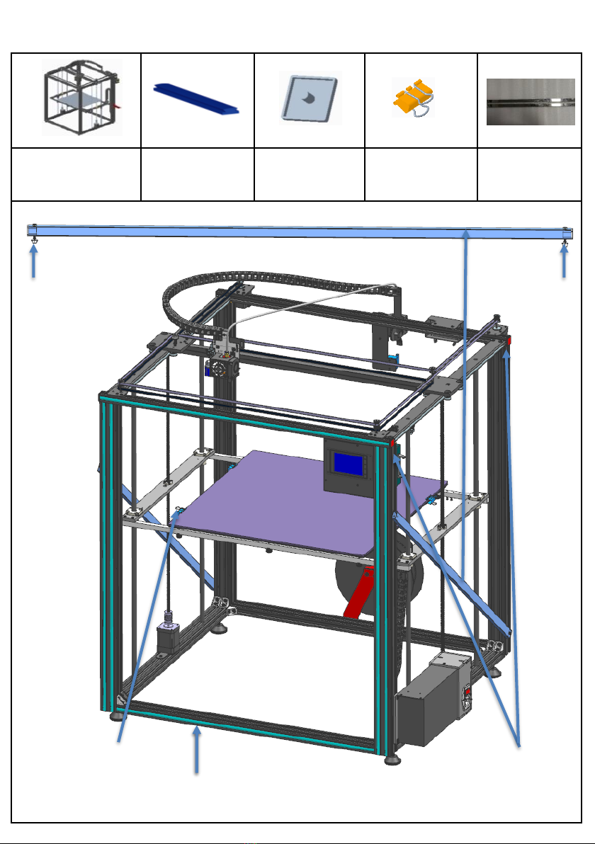
Step 12:Black sticker and seal assembly
15
seal
4-end cap
4-clips
boat nuts M4 boat nuts M4
Fix stainless steel rod to both sides of printer
Table of contents
Other TRONXY 3D Printer manuals

TRONXY
TRONXY X5S 2E User manual

TRONXY
TRONXY X5 User manual

TRONXY
TRONXY P802M User manual

TRONXY
TRONXY X1 User manual

TRONXY
TRONXY XY-2 PRO User manual

TRONXY
TRONXY X5SA-400-2E User manual

TRONXY
TRONXY X5SA-500 User manual

TRONXY
TRONXY X3A User manual

TRONXY
TRONXY Ultrabot User manual

TRONXY
TRONXY X5SA User manual

TRONXY
TRONXY X6-2E User manual

TRONXY
TRONXY VEHO 600-2E User manual

TRONXY
TRONXY X5SA-500-2E User manual

TRONXY
TRONXY X5S User manual

TRONXY
TRONXY X3A User manual

TRONXY
TRONXY D01 User manual

TRONXY
TRONXY X3A User manual

TRONXY
TRONXY XY-3 User manual

TRONXY
TRONXY XY-2 User manual

TRONXY
TRONXY X5SA-400-PRO User manual


