TRONXY X6-2E User manual
Model name:X6-2E
Instructions
深圳市创星元科技有限公司
SHENZHEN TRONXY TECHNOLOG CO.,LTD

j. Cannot provide Valid documents or Beyond the warranty period.
Precautions for use
Before using this machine, please carefully read this manual and the following notes:
1. Keep children away from the machine when using the machine. Children are
forbidden to touch the machine in use.
2. Please put the machine on a stable surface before using the machine.
3. Please keep this manual for future reference.
4.The open hole of the housing is strictly prohibited to cover, which is used for
ventilation and heat dissipation of the machine to avoid overheating.
5.Please pay attention to the notice and warning posted on the machine to
avoid danger or injury.
6.It is strictly forbidden to use the machine in the environment of inflammable
and explosive substances.
7.It is strictly forbidden to pour any liquid or dust into the machine, or it will
damage the machine or even cause a dangerous accident.
8.Please do not disassemble or repair the machine without permission. In
addition to normal quick assembly steps and common problems, please ask a
professional to help.
9.Do not use the machine under high temperature (above 85 ° C) environment,
otherwise may damage to the machine.
11.For use of the machine, the following is not covered by warranty:
a.Due to abnormal external forces (such as fall, extrusion, knock against,
impact) caused by the damage of products;
b.Product damage caused by violation of product operation manual;
c.Product damage caused by using materials that are not compatible with or
have not been recognized by relevant national standards;
d.Beyond use under the conditions of use (such as the mainboard working
environment for 5 to 40 ℃, customers in the above 40 ℃ or below 5 ℃ when
used under the condition of damage).
g.Damage caused by irresistible external factors.
h.Normal consumption of parts, such as printing plateform, nozzle and other
accessories.
i. Damage by Pure artificial condition
10.When unattended, it is recommended not to run the printer.
e.Damage caused by privately modifying firmware and appearance structure.
f.Damage caused by improper storage (such as dampness, mildew, etc.).

Print size
Power
input
Pocision
Power
Print
Certificate
Nozzle
size
Connectio
n
Print color
Hotbed
Material
Nozzle
Display
Ambient
temperat
Print
ambient
Machine
material
slicing
software
Machine
weight
files
format
Packing
weight
operation
software
Packing
size
Operaton
system
Machine
Power
110V/220V AC,50/60Hz
DC 12V 20A
CE FCC
USB interface.TF card
PLA.ABS
0.1mm-0.4mm optional
Aluminium profiles,sheet
metal
≈10.1kg
220*220*210
X/Y0.0125mm,Z0.02mm
20-100mm/s(advise 60mm/s)
0.2mm,0.3mm,0.4mm
optional
Dual color
≈12.3kg
500*530*220mm
470*445*407
1. Product parameters
3.5 inches full color touch
screen
8-40°C
support
Maxium260°C
20-80%
Repetier-Host.Cura
WinXP/Win7/MacOS
support
TRONXY exclusive slice
software
STL.OBJ.DAE.AMF.G-Code
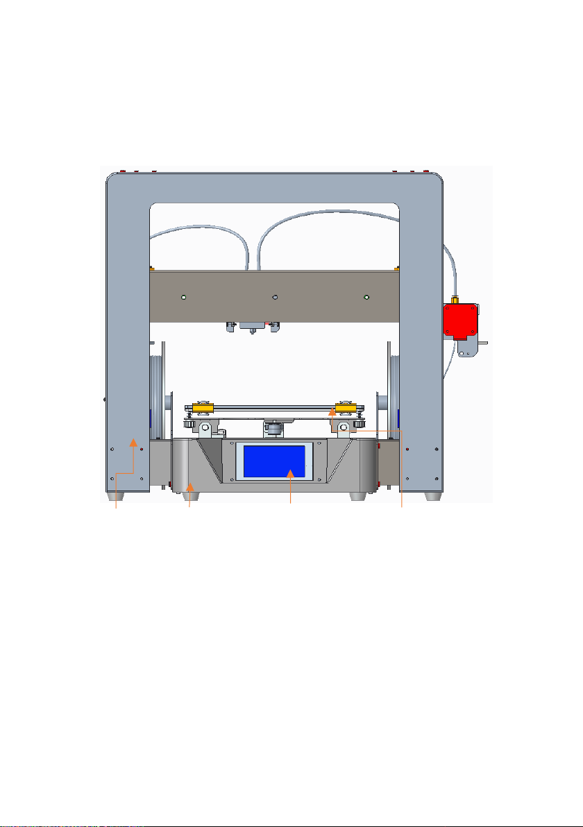
Gantry bracket The base X axis platform
2. Machine Introduction
Touch screen
1.Front view
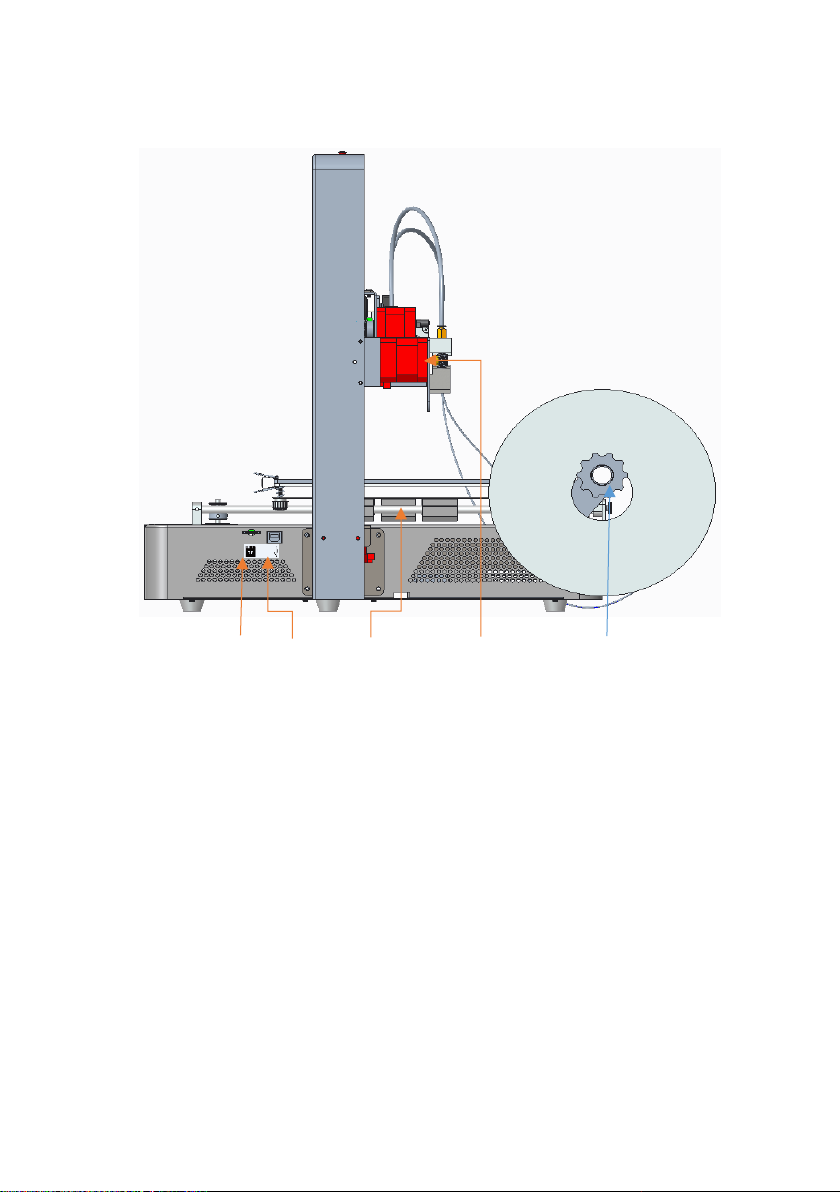
FT card slot, USB Y polished rod Right feeder
2.Right view
The right material shelf

the left material shelf
Adjusting nut left feeder
3. Left view
110V/220V selection port
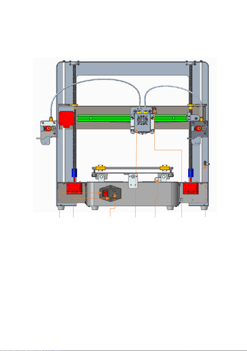
4.Back view
Power switch Power fuse Power cord connector Two-color extruder Y shaft switch X shaft switch Z shaft switch
3. Product assembly
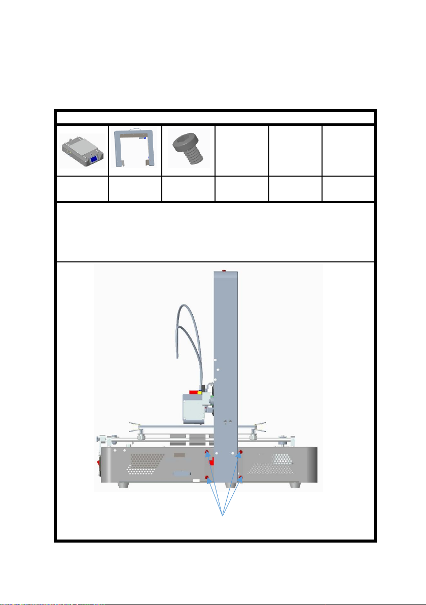
Step 1: assemble the base and the rack (take care to avoid scratching
parts when taking and assembling).
Assembly parts:
The base
1pcs
shelves
1pcs
screwPM4*6
8个
PM4*6 screws
to pass through the hole in the position as shown in the figure, and lock it with
the M4 tooth hole on the base.
Take out the bottom rack from the packing box and put it on the shelf, as
shown in the figure. Align with the position as shown in the figure, and use 8
PM4*6 screws
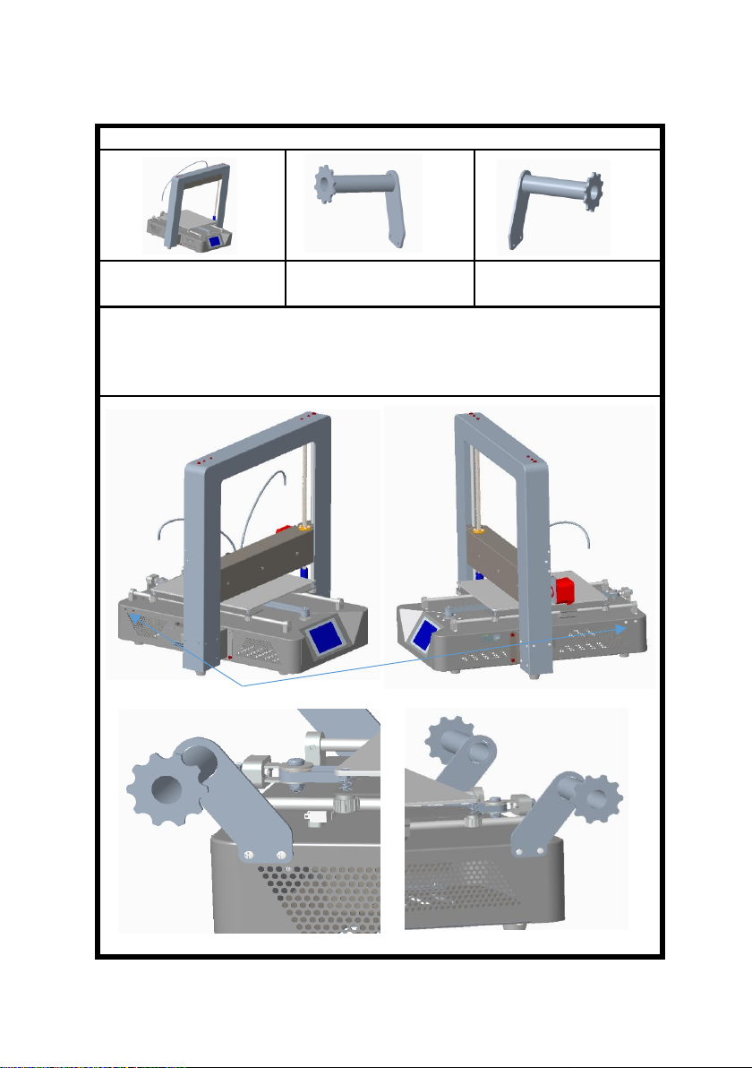
Loose screw
Loosen the 2 screws on the left and right sides of the cabinet, take 1 piece of
left and right material rack as shown in the figure,
place it according to the position shown, align the holes, and lock it with 2
screws.
printer 1pcs
left rack parts 1pcs
right rack parts 1pcs
Step 2: assemble the filament rack
Assembly parts:

screws PM3*4
feeder parts
2pcs
printer 1pcs
screws PM3*4
screws PM3*4 6pcs
Assembly parts:
Step 3: feeder assembly
2. Insert the material tube into the air nozzle hole of the feeder.
1. Screw through the machine sheet metal hole, align with the screw tooth hole
of the feeder component, and then lock it, as shown in the figure.
12 p female terminal
Assembly parts:
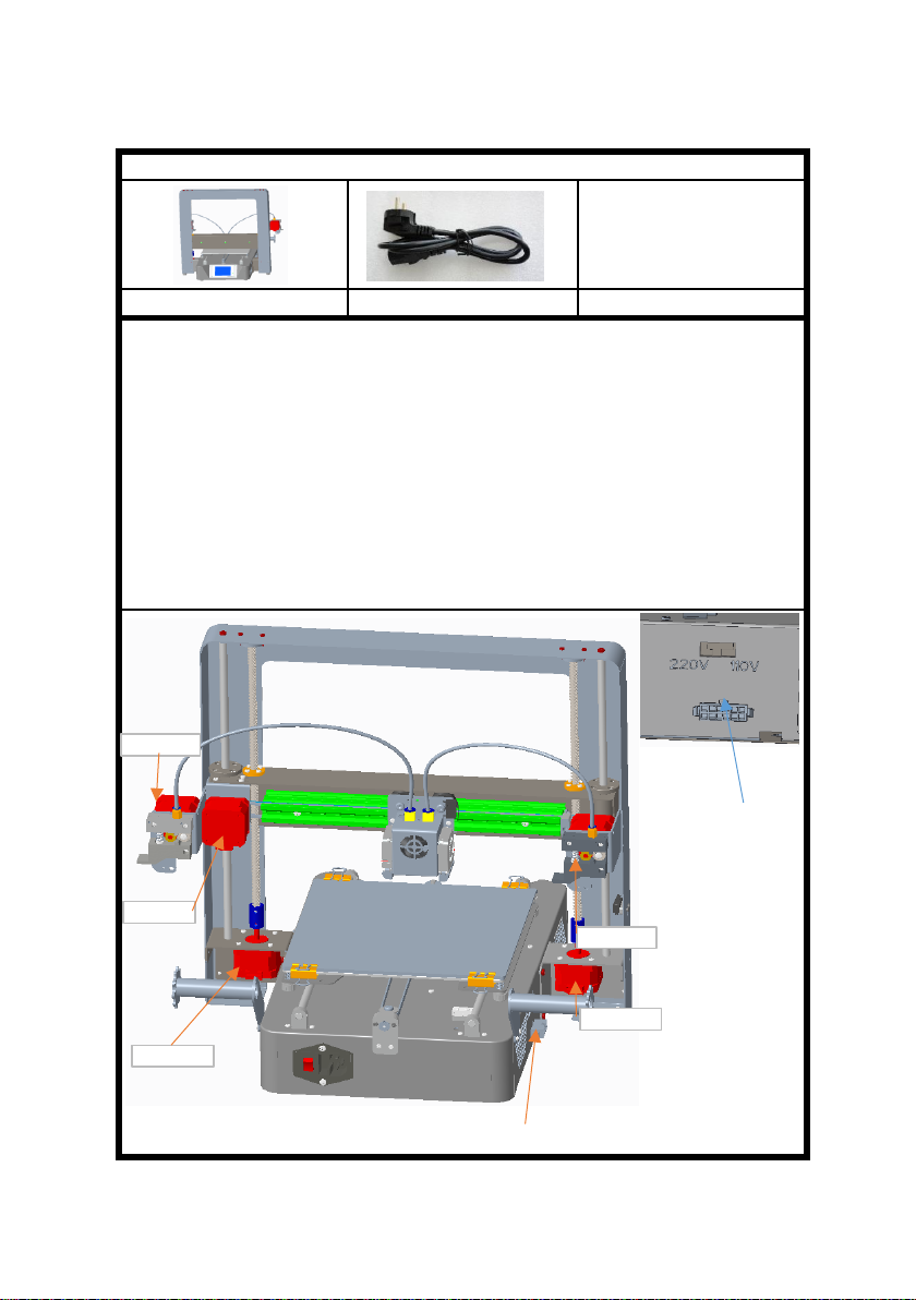
You can select 110V voltage.
5.Remove the power cord and plug into the 3P port of the host power supply.
printer(included wiring) 1pcs
4.According to the local voltage, select the power supply voltage of the host. As
shown, the position shift is 220V, and the toggle switch is to the right.
The rest is plugged into e2-motor.
Step 4: wiring
Power supply
voltage
selection
Make sure the debugging is good.
1. Insert the male terminal of the shelf 12P wire into the female terminal of the
left rear side of the base.
2. 2Motor 6P terminals protruding from the left back side of base, short plug in
z1-motor, long plug in e1-motor.
3. 3 Motor 6P terminals protruding from the right rear side of the base are
inserted into z2-motor for short while x-motor for long.
Power line 1pcs
X-MOTOR
Z1-MOTOR
Z2-MOTOR
E1-MOTOR
E2-MOTOR

as shown in the figure.Basic functionality for displaying submenus.
2.Click the system menu and enter it into the system submenu, as shown
in the figure: click the return menu and return to the superior menu.
2.1Click the state, and the display is as shown in the figure: the machine
position state parameters are displayed.
Click back menu to return to the superior menu.
4. Operational guidelines
1.Enter the main screen of the startup, display the system, tools, and
print three main menus. Click on each of the three sub-menus,

2.3Click the Chinese location menu to enter Chinese and English.Click back
menu to return to the superior menu.
2.2Click the machine information and the display is as shown in the
figure: the machine brand, ID, version and other information are
displayed.
Click back menu to return to the superior menu.
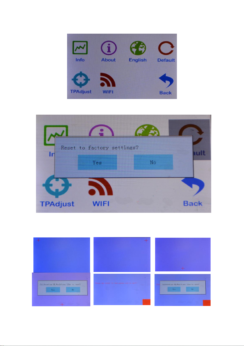
2.5Click the screen correction icon to enter the screen correction and
click the cross position for correction.
2.4Click the factory setting and ask if the factory setting is restored.Click
to return to restart and restore the factory Settings.
Adjust the screen when the menu is off, save it back.
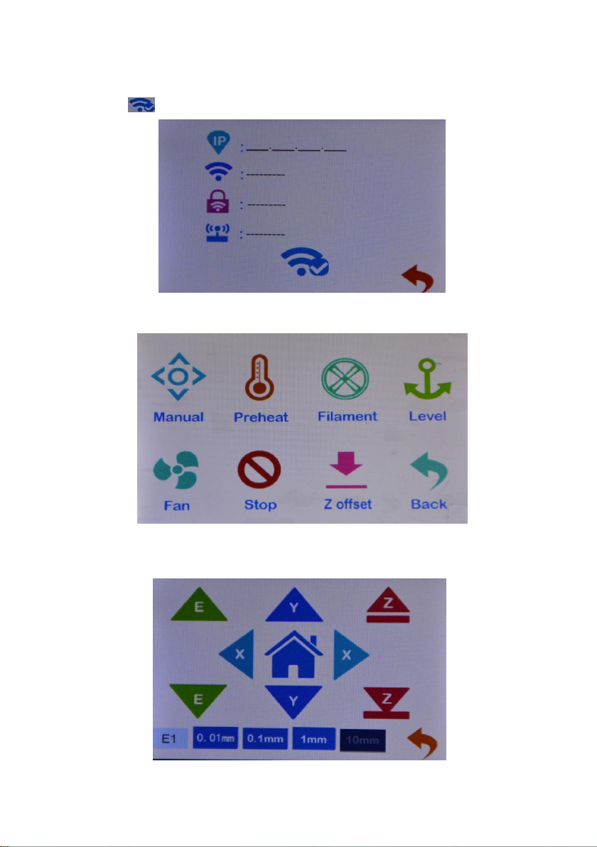
2.6Click the WIFI menu to enter WIFI parameter setting.Save Settings click on
the icon to return.
3.Click the tools menu to enter the machine parameter setting
and adjustment.
3.1.1 Click the manual menu to enter the manual adjustment
mode.Adjust the motor rotation, E extruder feeding/discharging, XYZ
shaft motor moving.ICONS 0.01mm, 0.1mm, 1mm, 10mm,
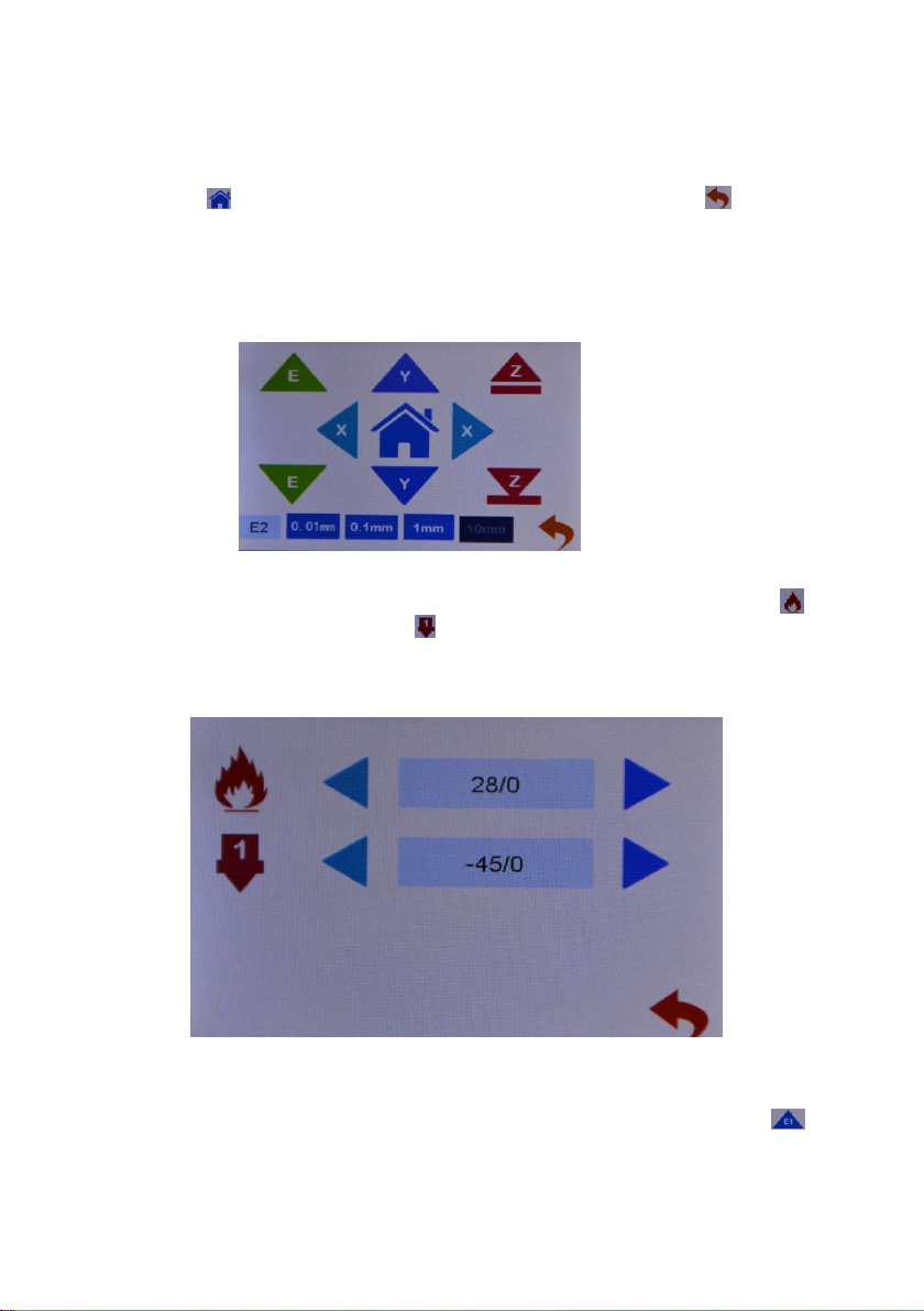
3.1.2 Click on the E1 icon, and the E1 icon changes to show E2. Click on
the E2 icon againto show E1, as shown in figure E1E2. Click on the
switch state.When displaying E1,click icon E to start extruder 1; when
displaying E2, click icon E to start extruder 2.
3.2Click the preheat icon, as shown in the figure, to set the heating
temperature of the machine extrusion head and the hot bed, the icon
hot bed heating and the icon hot head heating, and click the icon
on the right and left direction to adjust the setting temperature heating.
Use the heating function when replacing filaments.Click the digital icon
to directly switch to the preset temperature.
Set the heating temperature, the temperature reached, click the icon
to return the material.When installing the consumables, insert the
consumables directly into the feeder hole
After clicking, the dark color is displayed, such as icon 10mm, indicating
that each click of motor stroke moves 10mm.
Click the icon and the machine returns to the origin.Click back
to the parent menu.
3.3Click the icon of loading and unloading filaments to indicate
preheating.Remove the filaments to warm up before pulling them out

and click the icon to send the materials to the nozzle to flow the
materials.Click the icon motor to stop.Single side feed can not be
too long,Avoid plugging the hot material into the cold end of E2.E2
motor filaments feed back and forth.changed to E2,click
filaments return,click filamenst in。
and press down the feeder pressing block. As shown in the figure, pass
the filaments through the feeder to the material pipe,
3.4Leveling menu, auto leveling function, click the icon to enter auto
leveling.The machine reads the parameters of the leveling point and
saves them.Automatic leveling function selection.This function is not
available on this machine.
Adjusting nut
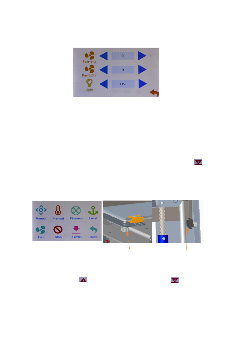
3.6.1Click the emergency icon, the machine stops in the current state,
and the motor unlocks.When adjusting the gap between the printing
platform and the nozzle, use emergency stop to let the extruder slide
freely.Gap size, with a piece of A4 paper between the nozzle and the
platform sliding resistance, but do not tear the paper is appropriate.The
platform should be positioned near the support point of the
platform,The platform should be positioned near the support point of
the platform, but avoid screw holes. Adjust each support point.
3.6.2Will print platform of the first four adjusting nut is tightened, the
spring pressure in the shortest possible location, click on the icon ,
extrusion head down, run into the Z axis stop switch, adjust the position
of the switch, to squeeze head nozzle and the platform about 2-3 mm
apart, then loosen the adjusting nut, fine-tuning platform for extrusion
head nozzle and the mobile platform about 2-3 mm apart, Distance
from the nozzle to an A4 sheet of paper thickness.
3.7Click the Z offset icon to enter the Z axis position adjustment.The
function of automatic leveling is effective.Select the fine tuning 0.1mm
icon, click the icon Z axis to move up, and click the Z axis to
move down.djust the nozzle and platform to A4 paper thickness. Click
the icon set Z to zero and save the setting.
This function is automatically leveling Z axis compensation, with leveling
function used, leveling simple.This function is not available on this
machine.
The Z axis switch
3.5Click the fan icon to enter the fan setting, and turn the fan value 0
OFF, 100 ON, light ON, and light OFF.

4.2Click on the file and select the file, which is sliced, to enter the file
screen.Click the icon to delete the file.Click the icon to enter
print mode.
Top left frame preview model;The right picture frame shows the status
parameters, the green hourglass shows the printing time,and the blue
hourglass shows the time needed after printing.Indicates the printing
speed by the number of the icon,the name of the printing file by the
icon, and the printing progress by the percentage.
4.1Click on the print icon to enter print.The screen displays the files in
the machine memory card.
Click the arrow to scroll up and down.Click the folder, open the folder,
and display the folder contents.

4.2.1Click the icon to stop printing and ask if the filaments should
be replaced.To replace the filaments,click YES to replace the filaments as
step 3.3 and return to continue printing.Click NO and go back to print.
4.2.2Click the icon to stop printing, and the machine asks if the state
is saved. Select "YES".The next printing will start from the current
state.Select NO, machine state reset.Click cancel to continue
printing.This function continues for breakpoint.After the model print
stops, the stop save state is shut down, and you can continue printing
after the next start.Boot prompt last print interrupt, select YES continue
last print.
Table of contents
Other TRONXY 3D Printer manuals

TRONXY
TRONXY X5SA User manual

TRONXY
TRONXY X5SA-400-2E User manual

TRONXY
TRONXY XY-3 User manual

TRONXY
TRONXY X3A User manual

TRONXY
TRONXY X5SA-500 User manual

TRONXY
TRONXY X5S User manual

TRONXY
TRONXY VEHO 600-2E User manual

TRONXY
TRONXY X1 User manual

TRONXY
TRONXY XY-2 PRO User manual

TRONXY
TRONXY VEHO600 User manual

TRONXY
TRONXY X6D User manual

TRONXY
TRONXY X5S 2E User manual

TRONXY
TRONXY X3A User manual

TRONXY
TRONXY X5SA-500-2E User manual

TRONXY
TRONXY XY-3 PRO V2 User manual

TRONXY
TRONXY X3A User manual

TRONXY
TRONXY XY-2 User manual

TRONXY
TRONXY X5 User manual

TRONXY
TRONXY X5SA-400-PRO User manual

TRONXY
TRONXY D01 User manual


