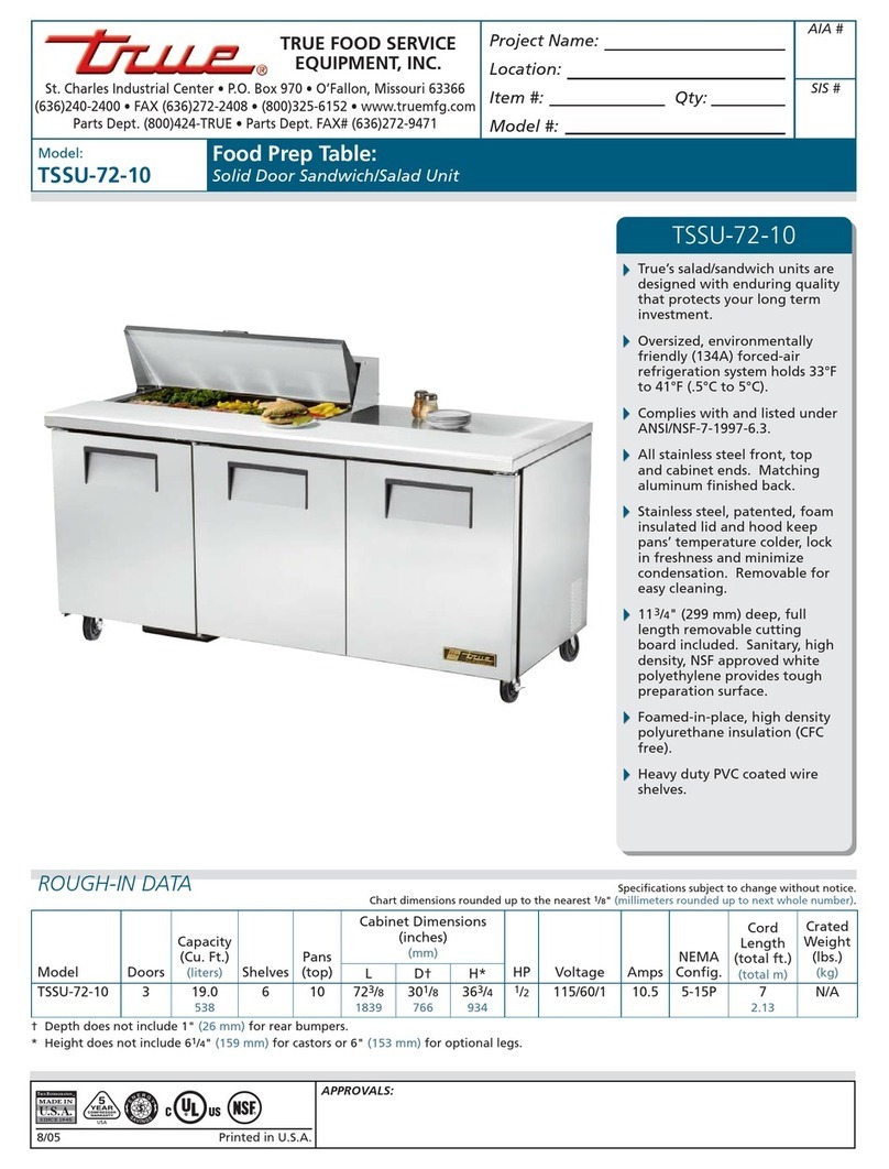
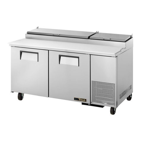
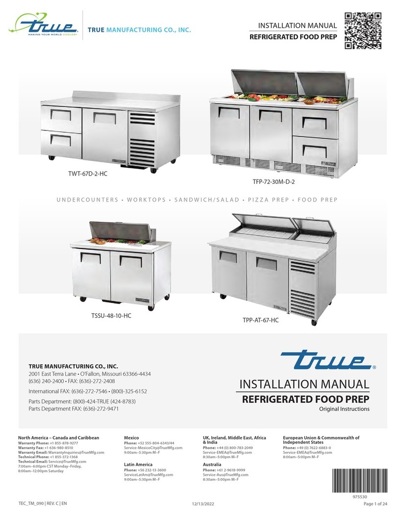
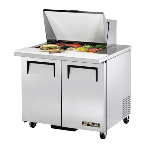
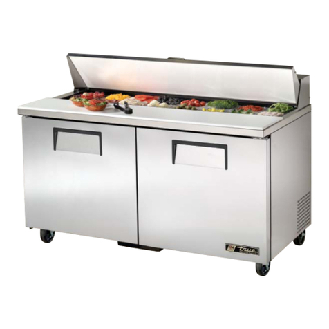
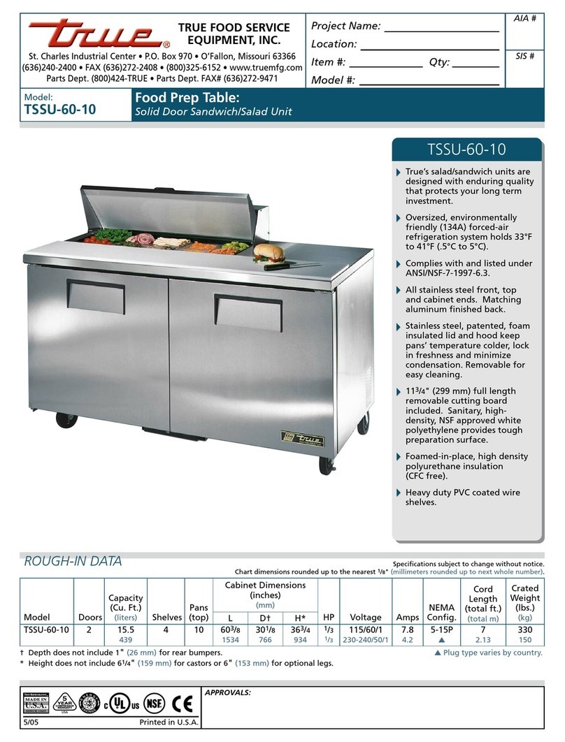
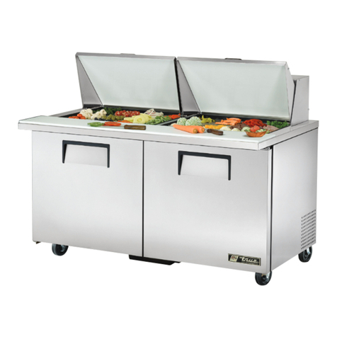
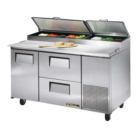
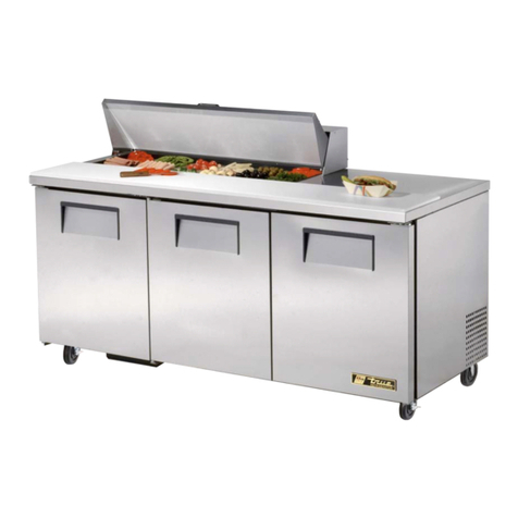
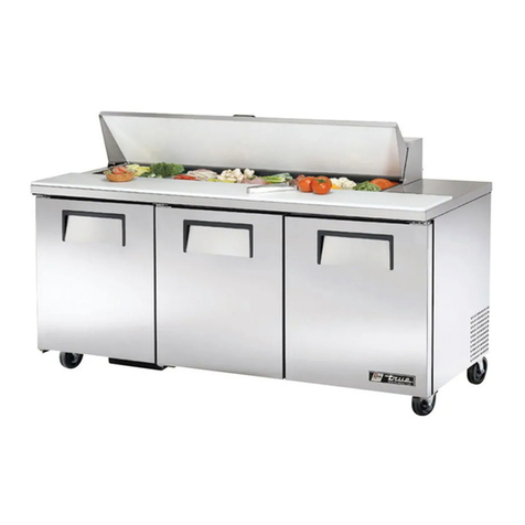
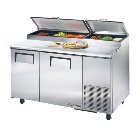
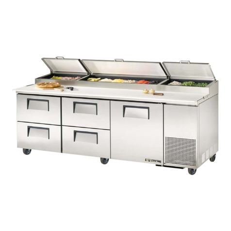
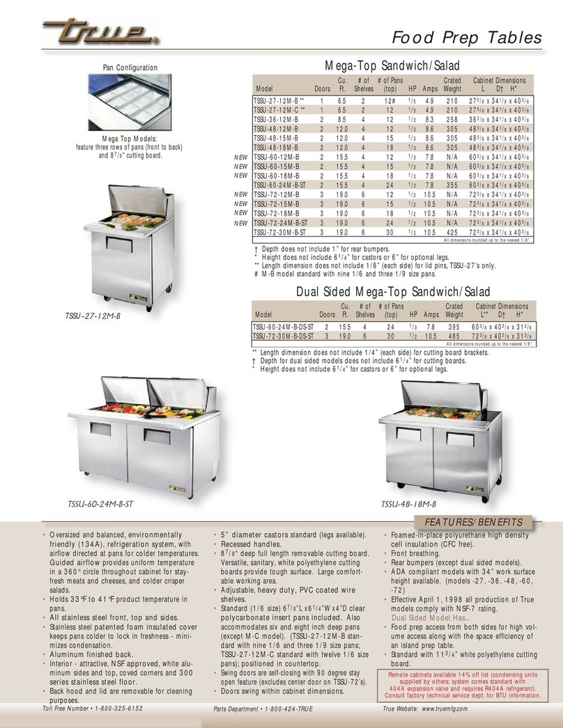
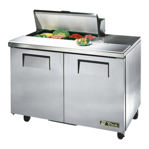
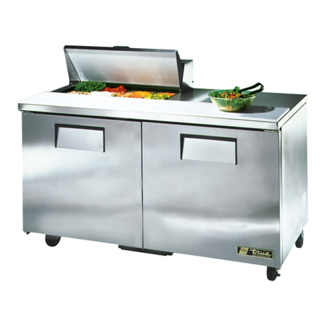
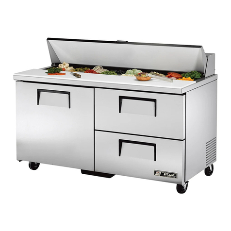
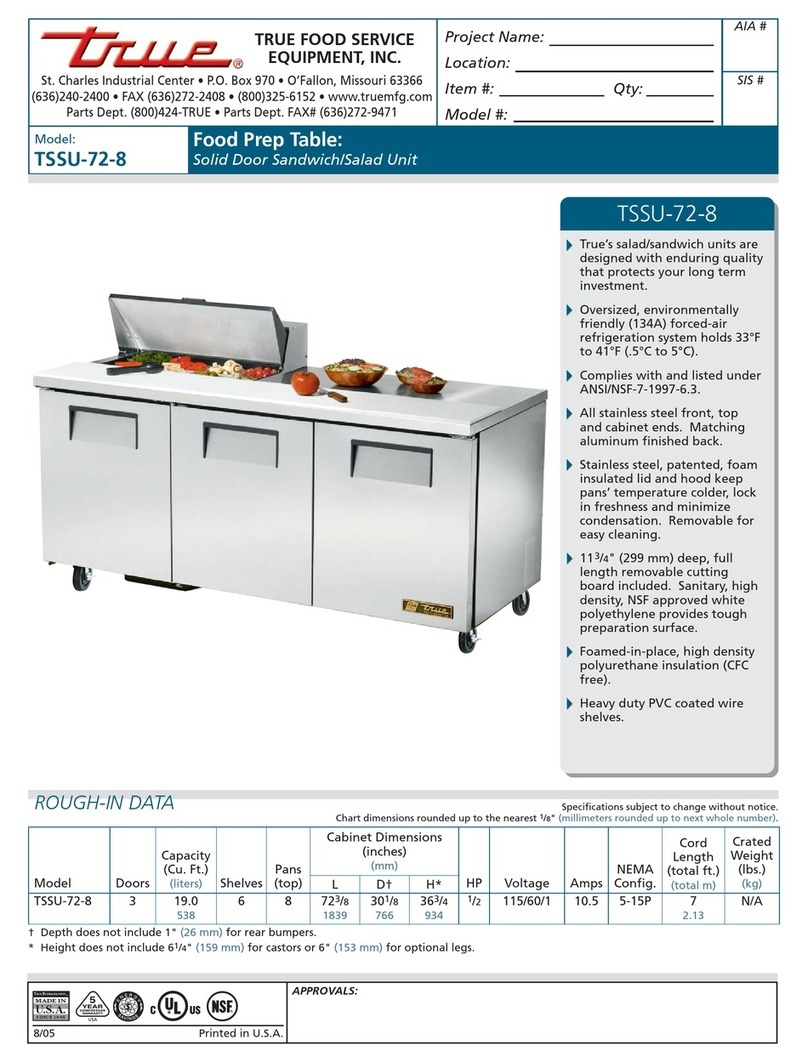
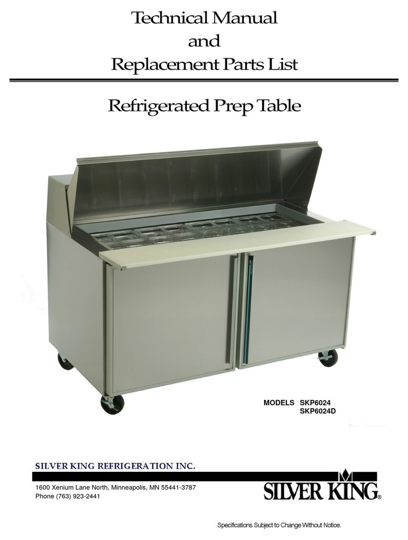
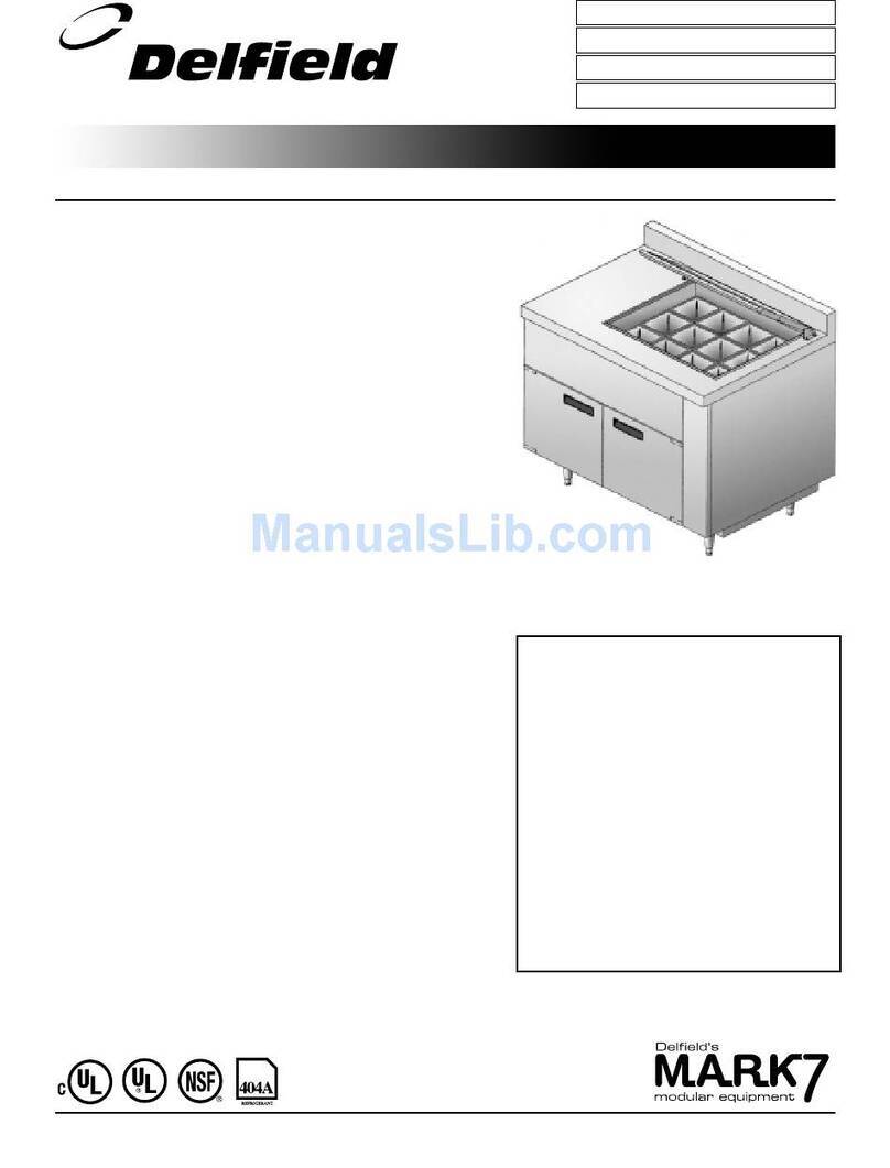
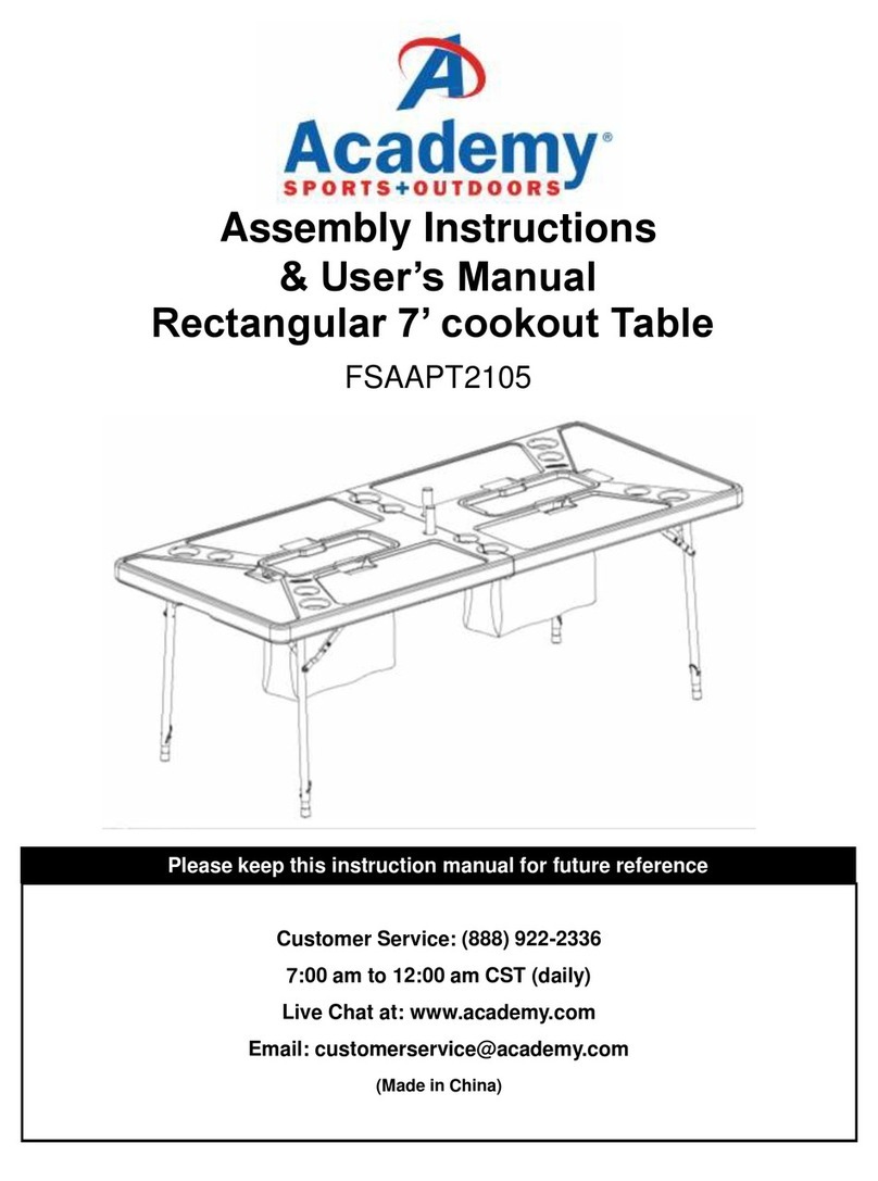
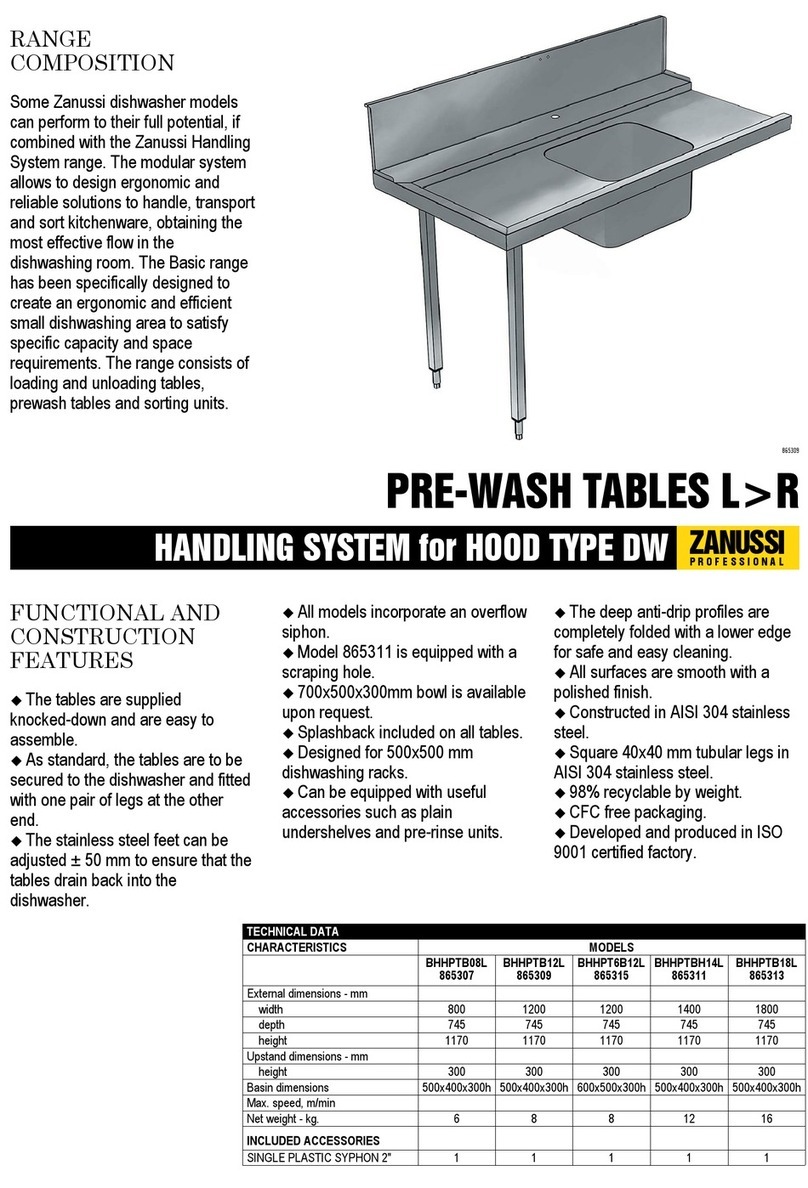
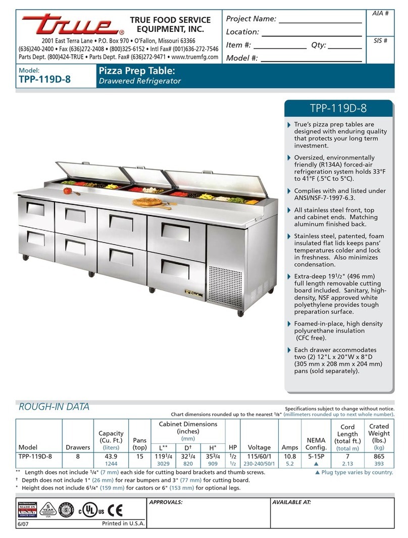
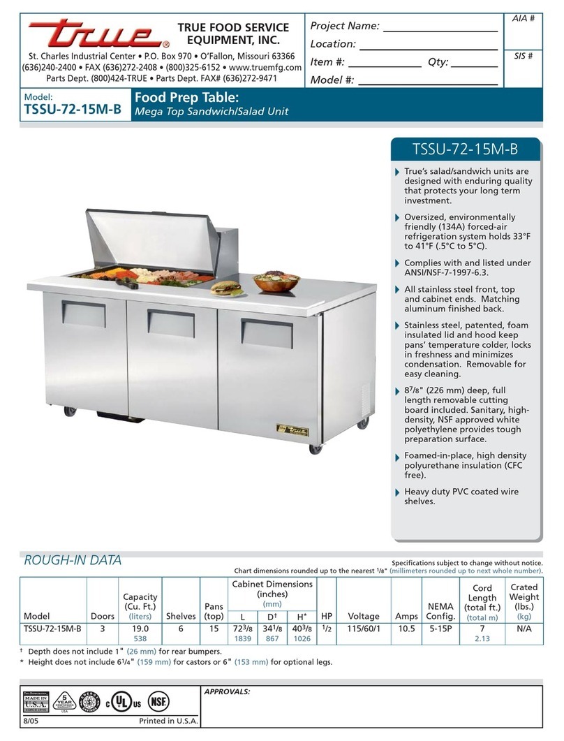
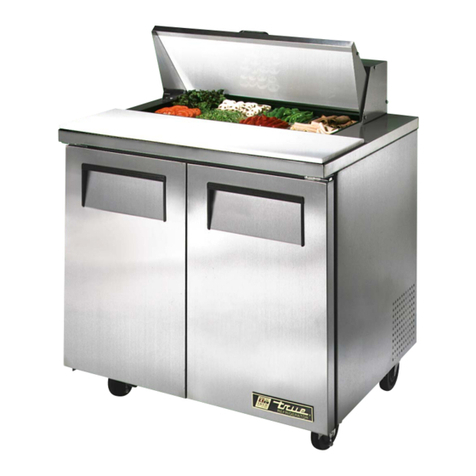
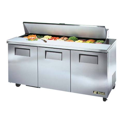
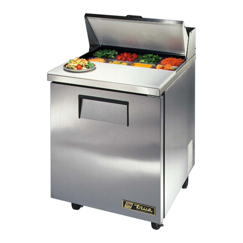
True TWT-67D-2 User manual

TABLE OF CONTENTS
Safety Information
Safety Precautions 1
Proper Disposal 2
Connecting Electricity 3
Adapter Plugs 3
Installation / Operation Instructions
Ownership 4
Required Tools 4
Uncrating 4
Locating & Clearances 5
Installation of Leg/Castors (TSSU, TWT, TUC, TPP) 6
Leveling and Castor Adjustment for TFP Models 7
Pizza Prep Tables 8
Installing TSSU Hood Cover 8
Leveling Cabinet 9
Electrical Instructions 9
Wire Gauge Chart 10
Start-up 11
Cabinet Air-Flow 11
Temperature Control Location & Setting for TFP 12
Temperature Control Adjustment High Altitude 12
LAE Temperature Control (TUC-24-HC/TUC-24G-HC) 13-19
TSSU-27-12M-C Chiller Hose 20
Shelving Install/Operation & Light Switch 21
TFP Drawer Removal & Installation 22
Maintenance, Care & Cleaning
Cleaning Condenser Coil 23-24
Stainless Steel Equipment Care & Cleaning 25-26
Composite Cutting Board Maintenance 26
Periodic Maintenance for Lids 27
Warranty (U.S.A. & Canada Only!) 28
INSTALLATION MANUAL FOR UNDERCOUNTERS,
WORKTOPS, SANDWICH/SALAD, PIZZA PREP, & FOOD PREP
UNDERCOUNTERS, WORKTOPS,
SANDWICH/SALAD, PIZZA PREP, & FOOD PREP
TRUE FOOD SERVICE EQUIPMENT, INC.
2001 East Terra Lane • O’Fallon, Missouri 63366-4434
(636)-240-2400 • FAX (636)272-2408 • INT’L FAX (636)272-7546 • (800)325-6152
Parts Department (800)424-TRUE • Parts Department FAX# (636)272-9471
CONGRATULATIONS!
You have just purchased the finest commercial
refrigerator available. You can expect many years of
trouble-free operation.
Spanish, German, French, Dutch, Portuguese, and
Polish versions included.
TPP-67
TWT-67D-2
TSSU-48-10
TUC-27
TFP-48-18M-D-4
(FOOD PREP (TFP) MODELS ONLY AVAILABLE IN 115v/60Hz VOLTAGE)
#970211 • SB • 2/14

True Food Service Equipment, Inc.
............ www.truemfg.com ............

11
True Food Service Equipment, Inc.
............ www.truemfg.com ............
SAFETY INFORMATION
• Thisrefrigeratormustbeproperlyinstalled
andlocatedinaccordancewiththeInstallation
Instructionsbeforeitisused.
• Donotallowchildrentoclimb,standorhangonthe
shelvesintherefrigerator.Theycoulddamagethe
refrigeratorandseriouslyinjurethemselves.
• Donottouchthecoldsurfacesintherefrigerator
compartmentwhenhandsaredamporwet.Skin
maysticktotheseextremelycoldsurfaces.
• Donotstoreorusegasolineorotherflammable
vaporsandliquidsinthevicinityofthisoranyother
appliance.
• Keepfingersoutofthe“pinchpoint”areas;
clearancesbetweenthedoorsandbetweenthedoors
andcabinetarenecessarilysmall;becarefulclosing
doorswhenchildrenareinthearea.
NOTE
We strongly recommend that any servicing be preformed by
a qualified individual.
• Unplugtherefrigeratorbeforecleaningand
makingrepairs.
• Settingtemperaturecontrolstothe0positiondoes
notremovepower.
• Danger-Riskoffireorexplosion.Flammablerefrigerantused.Donotusemechanicaldevicestodefrost
refrigerator.Donotpuncturerefrigeranttubing.
• Danger-Riskoffireorexplosion.Flammablerefrigerantused.Toberepairedonlybytrainedservicepersonnel.
Donotpuncturerefrigeranttubing.
• Caution-Riskoffireorexplosion.Flammablerefrigerantused.Consultrepairmanual/owner’sguidebefore
attemptingtoservicethisproduct.Allsafetyprecautionsmustbefollowed.
• Caution-Riskoffireorexplosion.Disposeofproperlyinaccordancewithfederalorlocalregulations.Flammable
refrigerantused.
• Caution-Riskoffireorexplosionduetopunctureofrefrigeranttubing;followhandlinginstructionscarefully.
Flammablerefrigerantused.
• Caution-Keepclearofobstructionallventilationopeningsintheapplianceenclosureorinthestructurefor
building-in.
WARNING!
Use this appliance for its intended purpose as described in this Owner Manual.
TO LOCATE REFRIGERANT TYPE, SEE SERIAL LABEL INSIDE CABINET.
This cabinet may contain fluorinated greenhouse gas covered by the Kyoto Protocol (please refer
to cabinet’s inner label for type and volume, GWP of 134a= 1,300. R404a= 3,800).
For Hydrocarbon Refrigeration Only (R-290) See Below:
How to Maintain Your TRUE Unit to Receive the Most Efficient and
Successful Operation
You have selected one of the finest commercial refrigeration units made. It is manufactured under strict quality controls with
only the best quality materials available. Your TRUE cooler when properly maintained will give you many years of trouble-
free service.
SAFETY PRECAUTIONS
When using electrical appliances, basic safety precautions should be followed, including the following:
22
True Food Service Equipment, Inc.
............ www.truemfg.com ............
SAFETY INFORMATION
PROPER DISPOSAL OF THE REFRIGERATOR
DANGER!
RISK OF CHILD ENTRAPMENT
USE OF EXTENSION CORDS
NEVER USE AN EXTENSION CORD! TRUE will not warranty any refrigerator that has been connected to an extension cord.
Childentrapmentandsuffocationarenotproblems
ofthepast.Junkedorabandonedrefrigeratorsarestill
dangerous…eveniftheywillsitfor“justafewdays.”If
youaregettingridofyouroldrefrigerator,pleasefollow
theinstructionsbelowtohelppreventaccidents.
Before You Throw Away Your Old Refrigerator or
Freezer:
• Takeoffthedoors.
• Leavetheshelvesinplacesothatchildrenmaynot
easilyclimbinside.
Refrigerant Disposal
Youroldrefrigeratormayhaveacoolingsystem
thatuses“OzoneDepleting”chemicals.Ifyouare
throwingawayyouroldrefrigerator,makesurethe
refrigerantisremovedforproperdisposalbya
qualifiedservicetechnician.Ifyouintentionally
releaseanyrefrigerantsyoucanbesubjectto
finesandimprisonmentunderprovisionsofthe
environmentalregulations.
REPLACEMENT PARTS
• Componentpartsshallbereplacedwithlikecomponents.
• Servicingshallbedonebyauthorizedservicepersonnel,tominimizetheriskofpossibleignitionduetoincorrect
partsorimproperservice.
• Lampsmustbereplacedbyidenticallampsonly.
• Ifthesupplycordisdamaged,itmustbereplacedbyaspecialcordorassemblyavailablefromthemanufactureror
itsserviceagent.

33
True Food Service Equipment, Inc.
Thepowercordfromthisapplianceisequippedwith
agroundingplugwhichminimizesthepossibilityof
electricshockhazard.
Havethewalloutletandcircuitcheckedbyaqualified
electriciantomakesuretheoutletisproperlygrounded.
Iftheoutletisastandard2-prongoutlet,itisyour
personalresponsibilityandobligationtohaveitreplaced
withtheproperlygroundedwalloutlet.
Therefrigeratorshouldalwaysbepluggedintoit’sown
individualelectricalcircuit,whichhasavoltagerating
thatmatchestheratingplate.
Thisprovidesthebestperformanceandalsoprevents
overloadingbuildingwiringcircuitswhichcouldcausea
firehazardfromoverheatedwires.
Neverunplugyourrefrigeratorbypullingonthepower
cord.Alwaysgripplugfirmlyandpullstraightoutfrom
theoutlet.
Repairorreplaceimmediatelyallpowercordsthathave
becomefrayedorotherwisedamaged.Donotuseacord
thatshowscracksorabrasiondamagealongitslengthor
ateitherend.
Whenremovingtherefrigeratorawayfromthewall,be
carefulnottorolloverordamagethepowercord.
HOW TO CONNECT ELECTRICITY
Do not, under any circumstances, cut or remove the ground prong from the power cord.
For personal safety, this appliance must be properly grounded.
WARNING!
USE OF ADAPTER PLUGS
NEVER USE AN ADAPTER PLUG! Because of potential safety hazards under certain conditions, we strongly recommend
against the use of an adapter plug.
............ www.truemfg.com ............
SAFETY INFORMATION
(North America Use Only!)
NEMAplugs
TRUEusesthesetypesofplugs.If
youdonothavetherightoutlethave
acertifiedelectricianinstallthecorrect
powersource.
Theincomingpowersourcetothecabinetincludingany
adaptersusedmusthavetheadequatepoweravailable
andmustbeproperlygrounded.Onlyadapterslisted
withULshouldbeused.

............ www.truemfg.com ............ 44
True Food Service Equipment, Inc.
INSTALLATION / OPERATION INSTRUCTIONS
............ www.truemfg.com ............
Toensurethatyourunitworksproperlyfromthefirst
day,itmustbeinstalledproperly.Wehighlyrecommend
atrainedrefrigerationmechanicandelectricianinstall
yourTRUEequipment.Thecostofaprofessional
installationismoneywellspent.
BeforeyoustarttoinstallyourTRUEunit,carefully
inspectitforfreightdamage.Ifdamageisdiscovered,
immediatelyfileaclaimwiththedeliveryfreightcarrier.
TRUE is not responsible for damage incurred during
shipment.
OWNERSHIP
• AdjustableWrench
• PhillipsHeadScrewdriver
• Level
REQUIRED TOOLS
Thefollowingprocedureisrecommendedforuncrating
theunit:
A. Removetheouterpackaging,(cardboardandbubbles
orstyrofoamcornersandclearplastic).Inspectfor
concealeddamage.Again,immediatelyfileaclaim
withthefreightcarrierifthereisdamage.
B. Moveyourunitasclosetothefinallocationas
possiblebeforeremovingthewoodenskid.
C. Removedoorbracketonswingglassdoormodels
(seeimage1-2).
NOTE
Keys for coolers with door locks are located in warranty
packets.
UNCRATING
INSTALLATION / OPERATION INSTRUCTIONS
1
2
Glass Door Models Only.
REMOTE UNITS (This section applies to remotes only!)
• Remotecabinetsmustbeorderedasremote.
Wedonotrecommendconvertingforastandard
selfcontainedtoremotesystem.
• Allremotecabinetsmustbehardwired.
• Nocastorsavailable.
• Allremotecabinetscomestandardusing404A
refrigerant.
• Allremoteunitscomestandardwithexpansion
valve,liquidlinesolenoid,heatedcondensatepan,
anddefrosttimerwhenapplicable.
• ContactTRUETechnicalServiceforBTU
requirements.
• Nowiringnecessarybetweencabinetand
condensingunit.
• Allremotecondensingunitspurchasedfrom
TRUEare208/230voltssinglephase.
If you have any questions regarding this section, please
call TRUE at 1-(800)-325-6152.

............ www.truemfg.com ............ 55
True Food Service Equipment, Inc.
INSTALLATION / OPERATION INSTRUCTIONS
A. Placepackingmaterialbehindcabinetasacushion.
Carefullylaytheunitonitsbacktoremoveskid.
When lifting unit remember to
leave the cabinet upright for 24 hours before
plugging into power source.
B. Removeskidbyunscrewingallbaserailanchor
brackets.Placeskidtotheside.
C. Carefullyliftcabinetupright.
D. Beforeremovingunitofftheshippingskidbesure
nottodamagedrainpanatthebaseoftheunit.
E. Appliancetestedaccordingtotheclimateclasses5
and7fortemperatureandrelativehumidity.
LOCATING
Removing skid from bottom of cabinet.
WARNING: Be sure there is adequate ventilation in your room. Under extreme heat conditions,
(100°F+, 38°C+), you may want to install an exhaust fan. Warranty is void if ventilation is insufficient.
CLEARANCES: (For proper cabinet operation, clearance guidelines should be followed.)
TPP, TSSU, TUC, & TWT
Unless otherwise noted – 1” at the rear, 0” at the sides, and 0” at the top.
TFP, TUC-24-HC, TUC-24G-HC-LD
0” at the rear, 0” at the sides, and 0” at the top.

............ www.truemfg.com ............ 66
True Food Service Equipment, Inc.
INSTALLATION / OPERATION INSTRUCTIONS
Thread castor into the underside of
cabinet frame rail.
Thread leg into cabinet bottom
frame rail.
The end of the leg is adjustable to
easy leveling.
Use the tool provided to tighten
the castor into place.
For leveling, insert the shim between
the castor and frame rail.
1 2 3
45
INSTALLATION OF LEGS AND CASTORS
TSSU, TWT, TUC, TPP
Important Safeguard for installation of leg/castor (Images 1-5 demonstrate procedure)
Securing Castors and Legs
Toobtainmaximumstrengthandstabilityoftheunit,itis
importantthatyoumakesureeachcastorissecure.Legsare
hand-tightenedsecurelyagainstthelowerrailassembly.The
bearingraceonthecastorofthetopedgeofthelegmust
makefirmcontactwiththerail.
Unit leveling
Fourlevelingshimshavebeenprovidedforlevelingcastored
unitspositionedonunevenfloors.Shimsmustbepositioned
betweenrailendandbearingrace.TRUErequiresafourshim
limittoeachindividualcastor.
A. Turnthebearingracecounter-clockwiseuntilthecabinet
islevel.Levelfronttobackandsidetoside.(diagonally)
B. Installthedesirednumberofshims,makingsuretheslot
oftheshimisincontactwiththethreadedstemofthe
castor.
C. Ifmorethanoneshimisused,turntheslotata90°angle
sotheyarenotinline.
D. Turnthebearingraceclockwisetotightenandsecurethe
castorbytighteningtheanchoringboltwitha3/4inch
open-endwrenchorthetoolprovided.
CAUTION
To avoid damage to lower rail assembly, slowly raise unit to
upright position.

............ www.truemfg.com ............ 77
True Food Service Equipment, Inc.
Adjusting Castors for Proper Leveling
Levelunit.Ifunitisnotlevelshimsarerequired.Follow
theseinstructionstoinstallshims.
1. Removefrontandreargrilldependinguponwhichcastor
needsadjusting.Locatethecastorbox.(Seeimage1).
2. Layunitonit’sback.Usesoftpackingmaterialandbe
carefulnottoscratchtheunit.Removepansandlidand
placethemtothesidebeforelayingunitonit’sback.
3. Eachunithasonecastorboxdifferentfromtheothers.
Thisboxistotallyinclosed.Removethiscastorboxfrom
bottomofunit.Backoutfourscrewsanchoringthebox.
Youwillneeda1/4”hexheadnutdrivertodisassemble
thiscastorbox.(Seeimage2).
4. Loosencastorwithtoolprovided.(Seeimage3).
5. Installthedesirednumberofshims,makingsuretheslot
oftheshimisincontactwiththethreadedstemofthe
castor.(Seeimage4).Ifmorethanoneshimisused,turn
theslotata90°anglesotheyarenotinline.
6. Afteradjustingcastorreassembleandreinstallcastorbox.
Thencarefullyuprightunitandreinstallpansandlid.
INSTALLATION / OPERATION INSTRUCTIONS
LEVELING AND CASTOR ADJUSTING
TFP MODELS ONLY
12
34
Locate castor box One castor box on each unit
is fully enclosed.
Loosen castor. Install shims.
Castor Box
Anchor
Screws

88
True Food Service Equipment, Inc.
............ www.truemfg.com ............
INSTALLATION / OPERATION INSTRUCTIONS
PIZZA PREP TABLES
A. Removereargrillandthreadelectriccordthrough
grommetingrill.
B. Replacegrill.
C. AligncuttingboardwithRivnutsandattachretainer
cliptotabletop(figure1).
D. Installthelidbrackets.Notethatthereisa
specificallydesignedleft,center(ifapplicable),and
rightbracket.
CUTTING BOARD
RETAINER
CLIP
TABLE TOP
Figure 1.
ANCHORING THE TSSU HOOD COVER
TSSU Hood Installation Instruction
Assembly
1.Locatethelid,(packagedwithinthecardboard
containerontopofthesaladsandwichunit),and
positionunderthehood.
2.Insertlidintohoodwhileflexingtheendsinward.
Makesurelidhandleisfacingoutofthehood.(See
image1).
3.Lettheendsofthelidflexbackintoposition.Hinge
pinslocatedinthehoodslideintosidesofthelid
hingepinholes.(Seeimage2).
1
2
Hood
Lid
Hinge Pin
Hinge Pin Hole

99
True Food Service Equipment, Inc.
............ www.truemfg.com ............
A. Beforeyournewunitisconnectedtoapowersupply,
checktheincomingvoltagewithavoltmeter.If
anythinglessthan100%oftheratedvoltagefor
operationisnoted,correctimmediately.
B. Allunitsareequippedwithaservicecord,andmust
bepoweredatproperoperatingvoltageatalltimes.
Refertocabinetdataplateforthisvoltage.
TRUE requires that a sole use circuit be dedicated for the
unit. Failure to do so voids warranty.
WARNING
Compressor warranties are void if compressor burns out
due to low voltage.
WARNING
Power supply cord ground should not be removed!
WARNING
Do not use electrical appliances inside the food storage
compartments of the appliances unless they are of the
type recommended by the manufacturer.
NOTE
To reference wiring diagram - Remove front louvered grill,
wiring diagram is positioned on the inside cabinet wall.
ELECTRICAL INSTRUCTIONS
A. Setunitinitsfinallocation.Besurethereisadequate
ventilationinyourroom.Underextremeheat
conditions,(100°F+,38°C+),youmaywanttoinstall
anexhaustfan.
WARNING
Warranty is void if ventilation is insufficient.
B. ProperlevelingofyourTRUEcooleriscriticalto
operatingsuccess(fornon-mobilemodels).Effective
condensateremovalanddooroperationwillbe
effectedbyleveling.
C. Thecoolershouldbeleveledfrominsidethecabinet.
Placealevelontheinsideflooroftheunitfrontto
backandsidetoside.
D. Ensurethatthedrainhoseorhosesarepositionedin
thepan.
E. Freeplugandcordfrominsidethelowerrearofthe
cooler(donotplugin).
F. Theunitshouldbeplacedcloseenoughtothe
electricalsupplysothatextensioncordsarenever
used.
WARNING
Cabinet warranties are void if OEM power cord is tampered
with. TRUE will not warranty any units that are connected to
an extension cord.
LEVELING
INSTALLATION / OPERATION INSTRUCTIONS

1010
True Food Service Equipment, Inc.
............ www.truemfg.com ............
INSTALLATION / OPERATION INSTRUCTIONS
Wire Gauge for 2% Voltage Drop in Supply Circuits
115 Volt Distance In Feet To Center of Load
Amps 20 30 40 50 60 70 80 90 100 120 140 160
2 14 14 14 14 14 14 14 14 14 14 14 14
3 14 14 14 14 14 14 14 14 14 14 14 12
4 14 14 14 14 14 14 14 14 14 12 12 12
5 14 14 14 14 14 14 14 12 12 12 10 10
6 14 14 14 14 14 14 12 12 12 10 10 10
7 14 14 14 14 14 12 12 12 10 10 10 8
8 14 14 14 14 12 12 12 10 10 10 8 8
9 14 14 14 12 12 12 10 10 10 8 8 8
10 14 14 14 12 12 10 10 10 10 8 8 8
12 14 14 12 12 10 10 10 8 8 8 8 6
14 14 14 12 10 10 10 8 8 8 6 6 6
16 14 12 12 10 10 8 8 8 8 6 6 6
18 14 12 10 10 8 8 8 8 8 8 8 5
20 14 12 10 10 8 8 8 6 6 6 5 5
25 12 10 10 8 8 6 6 6 6 5 4 4
30 12 10 8 8 6 6 6 6 5 4 4 3
35 10 10 8 6 6 6 5 5 4 4 3 2
40 10 8 8 6 6 5 5 4 4 3 2 2
45 10 8 6 6 6 5 4 4 3 3 2 1
50 10 8 6 6 5 4 4 3 3 2 1 1
Wire Gauge for 2% Voltage Drop in Supply Circuits
230 Volts Distance In Feet To Center of Load
Amps 20 30 40 50 60 70 80 90 100 120 140 160
5 14 14 14 14 14 14 14 14 14 14 14 14
6 14 14 14 14 14 14 14 14 14 14 14 12
7 14 14 14 14 14 14 14 14 14 14 12 12
8 14 14 14 14 14 14 14 14 14 12 12 12
9 14 14 14 14 14 14 14 14 12 12 12 10
10 14 14 14 14 14 14 14 12 12 12 10 10
12 14 14 14 14 14 14 12 12 12 10 10 10
14 14 14 14 14 14 12 12 12 10 10 10 8
16 14 14 14 14 12 12 12 10 10 10 8 8
18 14 14 14 12 12 12 10 10 10 8 8 8
20 14 14 14 12 10 10 10 10 10 8 8 8
25 14 14 12 12 10 10 10 10 8 8 6 6
30 14 12 12 10 10 10 8 8 8 6 6 6
35 14 12 10 10 10 8 8 8 8 6 6 5
40 14 12 10 10 8 8 8 6 6 6 5 5
50 12 10 10 8 6 6 6 6 6 5 4 4
60 12 10 8 6 6 6 6 6 5 4 4 3
70 10 10 8 6 6 6 5 5 4 4 2 2
80 10 8 8 6 6 5 5 4 4 3 2 2
90 10 8 6 6 5 5 4 4 3 3 1 1
100 10 8 6 6 5 4 4 3 3 2 1 1
CONDUCTORS AND CIRCUITS

1111
True Food Service Equipment, Inc.
............ www.truemfg.com ............
INSTALLATION / OPERATION INSTRUCTIONS
A. Thecompressorisreadytooperate.Pluginthe
cooler.
B. TemperaturecontrolsetatNo.4positiongives
refrigeratorsanapproximatetemperatureof35°F.
Allowunittofunctionseveralhours,completely
coolingcabinetbeforechangingthecontrolsetting.
C. Excessivetamperingwiththecontrolcouldleadto
servicedifficulties.Shoulditeverbecomenecessary
toreplacetemperaturecontrol,besureitisordered
fromyourTRUEdealerorrecommendedservice
agent.
D. GoodairflowinyourTRUEunitiscritical.Be
carefultoloadproductsothatitneitherpresses
againstthebackwall,norcomeswithinfourinches
oftheevaporatorhousing.Refrigeratedairoffthe
coilmustcirculatedownthebackwall.
NOTE
If the cooler is disconnected or shut off, wait five minutes
before starting again.
RECOMMENDATION
Before loading product we recommend you run your TRUE
unit empty for two to three days. This allows you to be sure
electrical wiring and installation are correct and no shipping
damage has occurred. Remember, our factory warranty
does not cover product loss!
REPLACEMENT PARTS
TRUE maintains a record of the cabinet serial number for
your cooler. If at any time during the life of your cooler, a
part is needed, you may obtain this part by furnishing the
model number and serial number to the company from
whom you purchased the cooler. Call Toll-Free: (800)-424-
TRUE (Direct to Parts Department). (800)-325-6152 (U.S.A.
& Canada only) or call: (636)-240-2400.
WARNING
REMOVAL OF BAFFLES IN CONDIMENT PAN AREA WILL
ADVERSELY AFFECT REFRIGERATION PERFORMANCE.
PLEASE LEAVE THE BAFFLES IN THE CORRECT LOCATION.
(See images below)
STARTUP
AIR-FLOW THROUGHOUT CABINET (TPP UNITS ONLY!)
Baffle in the correct location.

1212
True Food Service Equipment, Inc.
TERMS
Cut-out-Temperaturesensed
bythecontrollerthatshutsthe
compressoroff.
Cut-in-Temperaturesensedbythe
controllerthatturnsthecompressor
on.
REQUIRED TOOLS
•PhillipsHeadScrewdriver
•5/64”or2mmAllenWrench
•T-7TorxWrench
STEP 1
Unplugthecooler.
STEP 2
Removethescrewsthatsecurethe
temperaturecontroltotheinsetbox
lowerleftsideofthecabinet(when
facingthefrontofthecabinet).
STEP 3
Pulloutgentlyfromcabinet.
STEP 4
Forhighelevationinstallations,it
maybenecessaryto“warm-up”the
setpoints.Tomaketheadjustment,
inserttheappropriatetoolineach
adjustmentscrewandturn1/4ofa
revolutionclockwise(totheright).
Thisprocedurewilladjustboth
thecut-inandcut-outabout2°F
warmer.
STEP 5
Makesuretoreconnectthepink
wiretotheproperspade
terminalwhenreinstalling.
............ www.truemfg.com ............
INSTALLATION / OPERATION INSTRUCTIONS
NOTE
Mechanical temperature
controllers are affected when
functioning at high altitude.
The cut-in and cut-out
temperatures will be colder than
when the controller functions closer
to sea level.
Danfoss Temperature Control
(High Altitude Only!)
Cut-outAdjustmentScrewAllen(5/64”
or2mm)(clockwiseforwarmer)
Cut-inAdjustmentScrewTorx(T-7)
(clockwiseforwarmer)
CompressorConnection(pink)
TEMPERATURE CONTROL ADJUSTMENT FOR
HIGH ALTITUDE ONLY!
TEMPERATURE CONTROL LOCATION AND
SETTING - TFP UNITS ONLY
TFP Temperature control is located on
the back of the unit.
Set control to 5.

............ www.truemfg.com ............ 1313
True Food Service Equipment, Inc.
TUC-24-HC and TUC-24G-HC Only
DISPLAY

............ www.truemfg.com ............ 1414
True Food Service Equipment, Inc.
LAE CONTROL
SEQUENCE OF OPERATION
1. Cabinet is plugged in.
a. Display will illuminate.
b. Interior light will illuminate on glass door models only. (If lights do not come on please see
instructions on following page(s).) Solid door cabinet lights are controlled by door switch.
2. After the LAE control preprogrammed time delay of 3 minutes, the compressor and evaporator fan(s) will start if
the control is calling for cooling.
a. Control may be already pre-programmed from the factory so at the start of every compressor cycle or
during a defrost cycle, the condenser fan(s) will reverse for 30 seconds to blow dirt off the condensing
coil.
3. The LAE control will cycle the compressor but may also cycle evaporator fan(s) on and off determined by the
Set-Point and Differential temperatures. (If the Set-Point needs to be changed due to conditions please see
instructions on the following page(s).)
a. The Set-Point is the preprogrammed temperature which shuts off the compressor.
b. The Differential is the preprogrammed temperature that is added to the Set-Point temperature that will
start the compressor.
Example: If the Set-Point is -9°F/-23°C and the Differential is 10°F/5°C
(Set-Point) -9°F + 10 (Differential) = 1°F
Or
(Set-Point) -23°C + 5 (Differential) = -18°C
The compressor and evaporator fan(s) will cycle off -9°F/-23°C
and back on at 1°F/-18°C
4. The LAE control may be preprogrammed to initiate defrost by interval or at specic times of day. (If additional
Defrost Intervals or Cycles are needed or a Manual Defrost is required due to conditions please see instruc-
tions on the following page(s).)
a. At this time the “dEF” will appear on the display and compressor will turn off until a preprogrammed
temperature or duration is reached. During this time for freezers only, evaporator fan(s) will also
turn off and the coil heater and drain tube heaters will also be energized.
b. After the preprogrammed temperature or duration for defrost has been reached there may be a short
delay for both the compressor and evaporator fans to restart. At this time “dEF” may still appear
on the display for a short time.
True Manufacturing recommends that ONLY the Set-Point and/or
Defrost Interval may be adjusted due to certain conditions.
This sequence is NOT model specific.
If you have any questions, please contact the Technical Service Department.
Phone: 800-325-6152 • Email: service@truemfg.com

............ www.truemfg.com ............ 1515
True Food Service Equipment, Inc.
LOCKING & UNLOCKING LAE CONTROLLER
WHY:
LOCKING OF CONTROL IS NECESSARY TO PREVENT
CHANGES TO PROGRAM THAT MAY AFFECT CABINET
OPERATION
HOW:
A. Tochangelocksettingpressandreleasetheinfobutton
.“t1”willappear.Seeimage1.
Presstheupbuttonuntil“Loc”appears.
Seeimage2.
B. Whilepressingandholdingtheinfobuttonpress
theupordownbuttontochangethelock
settings.If“no”appears,thecontrollerisunlocked.If“yes”
appears,thecontrollerislocked.Seeimages3and4.
C. Oncethelocksettinghasbeensetcorrectlyreleasethe
infobutton.
Wait5secondsforthedisplaytoshowtemperature.
Seeimage5.
1
2
5
LAE Electronic Control
Info/Set Point
Button
Manual Defrost/
Down Button
Manual Activation/
Up Button
Stand-By
Button
3Image 3:
If “no” appears
on screen,
the controller
is unlocked.
4Image 4:
If “yes” appears
on screen,
the controller
is locked.
Compressor
Running
Activation of 2nd
Parameter Set - NA
Alarm - NA
Cabinet in Defrost
Evaporator Fan
Running
LAE Control Icons

............ www.truemfg.com ............ 1616
True Food Service Equipment, Inc.
HOW TO TURN GLASS DOOR MODEL
LIGHTS ON/OFF
WHY:
LIGHT MAY BE CONTROLLED BY LAE CONTROLLER OR
INTERIOR LIGHT SWITCH.
HOW:
A. Tocontrolinterior/signlightsbytheLAEController,
pressandreleasethe“ManualActivation”button.
B. Tocontrolinterior/signlightsbytheinteriordoor
switch,depresstherockerswitchtothe“ON”position.
LightSwitchislocatedoninsidetoprightofthe
ceiling.
ON Position
(Solid Door models lights are controlled by a door switch)
May need to unlock control.
LAE Electronic Control
Info/Set Point
Button
Manual Defrost/
Down Button
Manual Activation/
Up Button
Stand-By
Button
Compressor
Running
Activation of 2nd
Parameter Set - NA
Alarm - NA
Cabinet in Defrost
Evaporator Fan
Running
LAE Control Icons

............ www.truemfg.com ............ 1717
True Food Service Equipment, Inc.
LAE Electronic Control
Info/Set Point
Button
Manual Defrost/
Down Button
Manual Activation/
Up Button
Stand-By
Button
1
2
Compressor
Running
Activation of 2nd
Parameter Set - NA
Alarm - NA
Cabinet in Defrost
Evaporator Fan
Running
LAE Control Icons
May need to unlock control.
WHY:
THE SET POINT IS THE TEMPERATURE AT WHICH THE
COMPRESSOR WILL SHUT OFF.
Please note that the “set point” IS NOT the cabinet
holding temperature.
HOW:
A. Toseethesetpoint,pressandholdtheinfobutton.
Seeimage1.
B. Whilestillholdingtheinfobutton,
presstheupordownbuttontochange
the“setpoint”.
C. Oncethe“setpoint”hasbeensetcorrectlyreleasethe
infobutton.
edisplaywillshowtemperature.Seeimage2.
HOW TO CHANGE THE “SET POINT”

............ www.truemfg.com ............ 1818
True Food Service Equipment, Inc.
HOW TO INITIATE A MANUAL DEFROST
May need to unlock control.
WHY:
A ONE TIME ADDITIONAL DEFROST MAY BE NECESSARY
TO CLEAR ACCUMULATED FROST/ICE FROM EVAPORATOR
COIL.
HOW:
emethodtoinitiateamanualdefrostisdeterminedby
theDefrostModeParameter“DTM”preprogrammedin
thecontroller.
A.REGULAR TIME DEFROST (TIM)
Ifcontrollerispreprogrammedfor“TIM”,pressand
releasetheManualDefrostbuttonuntil“dEF”appears.
B.REAL TIME CLOCK (RTC)
Ifcontrollerispreprogrammedfor“RTC”presstheand
holdtheManualDefrostbuttonfor5secondsuntil
“dh1”appears.ReleasetheManualDefrostbuttonand
thenpressandholdforanadditional5secondsuntil
“dEF”appears.
DEFROST WILL ONLY TERMINATE ONCE A SPECIFIC PRESET TEMPERATURE
OR A PRESET TIME DURATION IS REACHED.
LAE Electronic Control
Info/Set Point
Button
Manual Defrost/
Down Button
Manual Activation/
Up Button
Stand-By
Button
Compressor
Running
Activation of 2nd
Parameter Set - NA
Alarm - NA
Cabinet in Defrost
Evaporator Fan
Running
LAE Control Icons
This manual suits for next models
5
Table of contents
Other True Food Prep Table manuals

True
True TSSU-36-12M-B User manual

True
True TSSU-60-24M-B-ST User manual

True
True TSSU-72-12M-B User manual

True
True TSSU-48-15M-B User manual

True
True TSSU-60-16-ADA User manual

True
True TSSU-72-10 User manual

True
True TSSU-27-8 User manual

True
True TPP-119D-8 User manual

True
True TPP-60 User manual

True
True TSSU-36-8 User manual

True
True TSSU-72-30M-B-ST User manual

True
True TPP-44 User manual

True
True TSSU-60-16D-4 User manual

True
True TSSU-48-12 User manual

True
True TSSU-72-30M-B-ST User manual

True
True TSSU-72-18-ADA User manual

True
True TPP-119 User manual

True
True TPP-93 User manual

True
True TUC-27 User manual

True
True TSSU-27-12M-B User manual