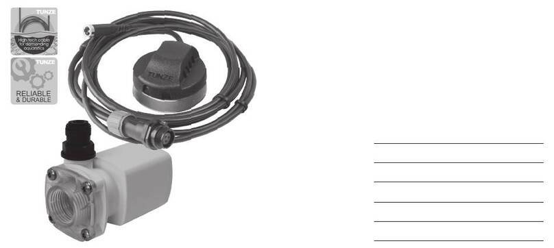
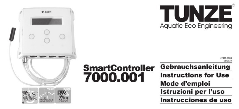
Tunze SmartController 7000 User manual

SmartController
7000
x7000.8888_E
01/2017
TUNZE
WEB
INTERFACE
TUNZE
HIGH PRECISION
MEASUREMENT
TUNZE
ALL-IN-ONE
SOLUTION
High Tech Aquarium Ecology
TUNZE®Aquarientechnik GmbH
Seeshaupter Straße 68
82377 Penzberg - Germany
Tel +49 8856 2022
Fax +49 8856 2021
info@tunze.com
www.tunze.com
1
Instructions for use
English
Contents
General information / scope of delivery
Technical data / accessories / spare parts / delivery state
Switching socket / CO2valve / Y-cable / combinations
Safety instructions / safety instructions for the magnet holder of the pH / mV electrode holder
Safety instructions for TUNZE®power supplies / wall mounting of the SmartController
Care and cleaning of the electrode
Basic settings with the touch panel – initial start-up
pH / CO2SmartController 7070.000 (setting using the touch panel)
Temperature SmartController 7028.000 / pumps, lamps (setting using the touch panel)
Settings for smart phone, tablet, or PC with WiFi
Integration into an existing WiFi network in the Access Point Mode
Integration into an existing WiFi network in the Client Mode
Reset of the Client Mode / important notice in case of incorrect depiction
Connecting multiple SmartControllers in the Access Point Mode / Client Mode
Access to the SmartController via the Internet / menu “Pumps”
Pulse mode – wave motion simulation
Interval mode – high and low tide simulation
Menu “Lamps” – lamp 1
Menu “Lamps” – season
Menu “Measurement”
Warranty / disposal
Page
2
3
4
5
6
7
8
9
10
11
11
12
13
14
15
16
17 - 19
20
21
22 - 23
24

e-jet
5005
nanostream®
6040
nanostream®
6055
nanostream®
6095
stream3
6150
stream
6155
stream
6105
stream
6255
SmartController
7000
2
High Tech Aquarium Ecology
This device is suitable for users (including children) with
limited physical, sensorial or mental abilities or without any
experience or previous knowledge, if suitable supervision or
detailed instructions on the operation of the device is provided
by a responsible person.
Please make sure that children do not play with the device.
Mains connection
Connector for pH or redox probe
Temperature
sensor
Splash-protected touchpad with
touch protection / parental control
Live display of pump performance
Transparent polycarbonate sleeve to protect from moisture
Four 3-in-1 connectors for
pumps / LEDs / controlled
power sockets / valves
Operating display for pumps
WiFi inside (for all OS)
Live display of temperature,
pH or redox
Wall mount
Scope of delivery
• SmartController 7000
• Temperature probe
• 4 control outputs with 4 connection cables each with a
length of 1.2 m (47.2 in.)
• Mounting set
Suitable for devices with Wi-Fi and browser.
Dimensions without mount (L x W x H):
133 x 33 x 116 mm (5.2 x 1.2 x 4.5 in.)
Up to 8 pumps or 8 LED 8850 lights are controlled with the
separately available Y-cable 7090.300 (7) (not included in the
scope of delivery!).
Ambient temperature: 0°- 45°C (32° - 113°F)
General information
The TUNZE®SmartController 7000 (1) combines all important
functions needed to create natural conditions within the
aquarium. It is able to control all Turbelle®electronic (2). In
addition, it also controls TUNZE®LEDs 8850 (3), CO2valves (4),
as well as switching sockets (5), for example, for 230 V valves
or ozone devices and power outlets for the timed on-switching
of lights. The Moonlight Turbelle®7097.050 (6) can also be
controlled by the SmartController 7000 according to the cycle.
In addition, it measures and regulates the temperature, the pH
value and Redox values. The settings can be easily performed
through a web interface with any WiFi-enabled device which
uses a web browser. But even without WiFi it is possible to
quickly and easily perform the basic settings via the touch panel.

SmartController
7000
3
High Tech Aquarium Ecology
Delivery state
Before each connecting/disconnecting of the connecting
cables to a Turbelle®pump or TUNZE®LED8850,alwaysrst
disconnect the power supply from the mains socket and switch
it off (14)!
The SmartController 7000 is supplied with 4 cables 7092.300
(15). One CO2valve (9) from the Valve Set 7070.200, one
switching socket outlet 7070.120 (10), one TUNZE®LED 8850
(16) or one Turbelle®pump (17) can be connected to each
cable.
Spare parts
(13) 7000.400 Wall mount for SmartController 7000
(14) 5012.010 Power supply unit 12 V
(15) 7000.891 Protective cap Ø 12.6 x 9.6 mm (0.5 x 0.4 in.)
Accessories
(1) 7040.120 Buffer solution for pH 7 and 9
(2) 7040.130 Buffer solution for pH 5 and 7
(3) 7075.150 Redox test solution +475 mV, 50 ml (1.7 oz.)
(4) 7040.200 Cleaning solution for electrodes
(5) 7070.300 pH / mV electrode holder
(6) 7070.100 pH electrode plastic
(7) 7070.110 pH electrode glass
(8) 7055.100 mV electrode glass
(9) 7070.200 CO2valve set
(10) 7070.120 Controlled Power Socket
(11) 7097.050 Moonlight Turbelle®
(12) 6105.500 Safety Connector
mV
with Controlled Power Socket 7070.120,
with mV electrode 7055.100.
Measuring range: -700 - 700 mV
Control range: 0 - 500 mV
Hysteresis: 0 and 5 mV
Settings only possible via WiFi.
Temperature
with Controlled Power Socket 7070.120.
Temperature scale: °C or °F
Measurement and control range: 5 - 50°C (41 - 122°F)
Hysteresis: 0 to 0.3 °C (0.54°F)
Technical data
Measurement and control range
pH
with Controlled Power Socket 7070.120, with CO2Valve
Set 7070.200 and pH electrode 7070.110 or pH electrode
7070.100.
The measurement is temperature compensated.
Measurement and control range: pH 1.5 - 12
Hysteresis: pH +0.02 and -0.05 mV

Additional power supply for SmartController 7000 – Safety Connector
Incaseofapowerfailure,theSmartControllernolongercontrolsanyoutput.Ifowpumpsareconnectedto
a safety connector 6105.500 (14), the SmartController 7000 must also be connected to a safety connector
(possibly same battery with 12 V).
The Safety Connector enables a normal operation with the TUNZE®power supply unit (15), but in case
of a power failure it will automatically switch over to a battery (16) or a DC power source. It should always
be ensured that the battery is in an optimal condition, by using a commercially available battery charger.
Indoor use of lead starter batteries for cars is inadmissible!
Never connect the SmartController 7000 directly to a battery or other DC power source or without a fuse!
The maximum DC voltage is 18 volts (switch-off limit) - if exceeded, the electronics will be destroyed!
A
B
24V
+ +
+ ++
+ +
12V
OR OR
SmartController
7000
4
High Tech Aquarium Ecology
Combinations
A switching socket or a valve can also be combined with a
Y-cable. Therefore it is possible to control 3 different devices
through a single socket.
Combinations:
(A) switching socket + Y-cable + pump + LED 8850
(B) switching socket or valve + Y-cable + 2 pumps or
2 LEDs 8850
If a switching socket or valves are connected to a socket
together with pumps or LEDs 8850, make sure that the
switching socketorthe valveisalwaysconnectedrst,and
then the pump or LED 8850 light only connected afterwards to
the supplied connector sockets of the switching socket / valve.
Y-cable
With the Y-cable 7090.300 (10), a further device can be
connected to a socket. Through this, two different devices
can be simultaneously controlled on a single socket (c), for
example, a Turbelle®pump and a TUNZE®LED 8850 (11).
Alternatively, two pumps (12) or two LEDs 8850 (13) can also
be operated on a single socket. With 4 Y-cables it is thus
possible to connect 8 Turbelle®pumps or 8 TUNZE®LEDs
8850 to the SmartController 7000 (5).
Caution!
When using a Y-cable it is only possible to connect
identical dimming LED lights with the same voltage, for
example, 2 x 8850.000 with 24 V (13a), or 2x 8810.000 /
8820.000 / 8830.000 with 12 V (13b). A combination of these
two lamps will destroy the 12 V lamp!
Switching socket /
CO2valve
The switching socket (Controlled Power Socket) 7070.120 (1)
and the CO2valve (2) from the CO2valve set 7070.200 each
have a connection (a) for the SmartController 7000 (3) and a
socket (b) for connecting additional TUNZE®LED 8850 (4) or
a Turbelle®pump (5).
Therefore, without an additional cable a switching socket (1)
or a valve (2) can be operated on a single socket / channel (c)
of the SmartController 7000 (3) together with a TUNZE®LED
8850 (4) or together with a Turbelle®pump (5).
It is, however,
NOT
possible to connect a switching socket and
a valve to a single socket / channel (c)!
When connecting a CO2bottle (6), ensure that the CO2 valve
(7) and the non-return valve (8) are correctly connected in the
direction of the arrow (9).
NO OTHER
CONTROL UNITS!
SmartController
7000
5
High Tech Aquarium Ecology
Safety instructions
for the magnet holder
of the pH / mV
electrode holder
Very strong magnet!
(7)
Keep the magnet holder out of reach of children!
Caution! Risk of injury!
(8)
Do not bring the magnet halves together! The magnet halves
cling together with a force of approx. 30 to 200 kg (66 to 441
lbs.), depending on the type of direct contact.
Only touch the magnetic parts on the sides with your hand.
Never place the hand or the ngers between the contact
surfaces (9)!
The magnets attracts metal parts and other magnets which
are less than 10 cm (3.94 in.) away with great force! When
handling the magnet, no metal parts, other magnets, blades
or knives should be within a vicinity of 10 cm (3.94 in.) in order
to avoid injuries.
Beware of magnetically sensitive items such as pacemakers,
data carriers, credit cards and keys. Maintain a minimum
distance of at least 30 cm (10.92 in.)!
When transporting the Magnet Holder, always use the supplied
spacer adapter.
Heating above 50°C (122°F) will lead to the destruction of the
magnet, or loss of the magnetic effect (10).
Safety instructions
Thee connection to third-party devices, for example, to a
different power supply or switch is not allowed (1)!
Only use the SmartController 7000 in aquariums whose
operation is also permitted outdoors (2).
Before putting the power supply into operation, please check
whether the operating voltage of the appliance corresponds
with the mains voltage.
Aquarium water temperature max. +35°C (95°F) (3).
Do not bend the probe cable and also do not use it to attach
the probe (4).
Absolutely observe the chapter “Care and cleaning of the
electrode”.
For the pH/CO2SmartController Set 7070.000: Water is
constantly absorbs CO2and moves it into the hose in the
direction of the valve. Therefore, unscrew the hose from the
metering valve, if the CO2bottle is depleted or the control
system is switched off.
The switching socket 7070.120 may only be opened only by
an electrician (5).
The SmartController 7000 and power supply must be protected
from moisture (6).
Keep the instruction manual in a safe place.

NO OTHER
CONTROL UNITS!
SmartController
7000
6
High Tech Aquarium Ecology
Wall mounting of the
SmartController
The SmartController 7000 can be mounted to smooth walls
with the supplied adhesive strips, or be screwed to the wall.
(Screws not included in the scope of delivery!)
A suitable wall must be dry and protected from splash water
and moisture.
The SmartController 7000 may under no circumstances be
attached above the Aquarium (4)!
Water from a pump connected to the SmartController 7000
could follow the cable and damage the device. To avoid this,
we recommend forming a loop with the cable or placing the
SmartController 7000 higher than the pump.
Observe the cable length of the devices because connecting
cables may not be extended.
Several TUNZE®controllers can be placed densely side by
side, and all cable outlets positioned at the bottom (5).
Route the cables in such a manner that no water can travel
along them and penetrate into the controller!
Safety instructions
for TUNZE®power
supply units
TUNZE®power supply units have not been designed for
outdoor operation (1).
In order to prevent water damage, the power supply unit should be
placed as far away from the aquarium as possible.
Operation is permitted only with a residual-current-operated
circuit-breakertted,max.30mA.
Before working in the a
quarium, please make sure that all electric
units in use have been di
sco
nnected from the mains.
Do not repair a damaged mains cable – repla
ce the unit
completely.
The connection to devices, such as electronic switches or
speed controllers, of other
makes is not permissible (2)!
The
SmartController 7000
on the pump cable is susceptible to
water and may be destroyed in case of water damage!
The operation of the
SmartController 7000
is permissible only
with the original TUNZE®power supply unit.
Mount the power supply unit in a dry and well-ventilated
position only.
Do not mount in the vicinity of heat sources (3).
Ambient temperature during operation: 0°C to +35°C (32°C
to 95° F)
Ambient humidity during operation: 30% - 90%
Storage temperature: -25°C to +80° Celsius (-13°F to 176°F)
Storage humidity: 30% - 95%

SmartController
7000
7
High Tech Aquarium Ecology
Care and cleaning of
the electrode
The accuracy of the pH or mV measurement depends on the
cleaning condition of the electrode. For this reason, it should
be treated with special care.
Never stick the electrode into the sand to test the pH or
mV value in the ground. The sensitive glass sphere could
be destroyed as a result, whereas the damage would be
irreparable and the warranty would become void. (1).
During the operation, the electrode should be half immersed
in water. Cable and screw connections must not come into
contact with water.
The cable of the electrode should not be pinched or
mechanically stressed.
A strong algae growth on the electrode will falsify the measured
value. Please mount in position which is as dark as possible.
A dirty or algae-covered electrode may not be cleaned
mechanically: the delicate glass membrane would be
destroyed (2).
Cleaning in intervals of 1 - 3 months
The electrode should be cleaned to avoid faulty measurements.
Please clean using the TUNZE®cleaning solution 7040.200 in
intervals of 1 to 3 months.
Let the electrode soak in the cleaning solution for about 10
minutes (3).
Then rinse with very clean water (aqua dest.) and dry with very
soft paper (4).
Service life of the electrode
If a clean electrode is properly stored, the self discharge
(consumption) is lower than when it is used in measuring
media. Therefore, the electrode tip should always be kept
moist between the measurements, and preferably stored in a
KCl solution. The electrode has a salt reservoir made of KCl (5)
on the inside. This salt reservoir will be gradually consumed. If
it is exhausted, there could be severe incorrect measurements
and the electrode must be replaced.
If the electrode is exposed to the open for several hours, the
membrane at the tip can dry out, resulting in a defect of the
electrode.
The service life of the electrodes during continuous operation
is approx. one to two years, whereas this time can usually be
extended with good care and occasional measurements. A
storage time of the mV or pH electrode for several months
beforerstuseonlyslightlyshortenstheservicelife,ifthetip
of the electrode remains in the protective cap with KCl solution
andiskeptmoist.Exactspecicationsaretherebynotpossible
here, because the lifetime depends on the respective usage.
The date of manufacture of the electrode is located on the
outer side of the electrode packaging.

display
enter
down
up
back
SmartController
7000
8
High Tech Aquarium Ecology
Basic settings with
the touch panel —
initial start-up
Connect the SmartController 7000 to the mains adapter
5012.010 as the power supply, and then connect to the power
grid (1).
The SmartController 7000 can be quickly adjusted without
a WiFi-capable device using the touch panel. This option is
especially interesting for the SmartController 7000 as a pH/CO2
controller (7070.000) or temperature controller (7028.000). Not
all settings can be performed the touch panel. Some functions
can only be performed through the web interface. The settings
of the redox value are possible over WiFi.
Touch panel interface:
Press enter to get into the menu.
Press on upward or downward until “System” appears in
the display.
Setting the time:
Press on enteragain→“time”willappearinthedisplay.
Conrmwithenter. Use the up / down keys to set the
time. Save with enter.
Enabling the food timer:
Press back for 5 seconds. It also works if the parental lock
is activated.
Select temperature scale:
Back to the menu, then up, then press enter again and
choose between °Celsius and °Fahrenheit. Save with enter.
Select language:
Back to the menu, then up, then press enter again and
choose between German and English. Save with enter.
Note: The language setting in the touch panel is independent
from the language setting in the browser (WiFi).
Setting the date:
Back to the menu, then upward→“date”willappearinthe
display.Conrmwithenter. Set the date with the buttons
up / down. Save with enter.
Parental lock:
Press enter and back simultaneously. After blinking
twice, the middle LEDs (2) will extinguish and a simple
touch protection will be enabled. Press enter and back
simultaneously again to deactivate.
In case of a possible failure of the touch panel / display:
Activate the food-timer, then disable it again. Should obscure
characters appear on the display, exit the menu by pressing
the back button or wait for some time.

display
up
back enter
down
1234
SmartController
7000
9
High Tech Aquarium Ecology
pH/CO2SmartController
7070.000
(setting using the touch panel)
Scope of delivery pH/CO2-SmartController
(1) SmartController 7000
(2) pH electrode made of glass 7070.110
(3) CO2valve set 7070.200
(4) Buffer solution for pH 5 / 7 7040.130
(5) pH / mV electrode holder 7070.300
Adjust pH:
Press enter to get into the menu.
Press on upward or downward until “pH value” appears in
the display.
Press on enter again → “pH control” will appear in the
display.
When you activate the pH control, the CO2valve 7070.200
(3) or the switching socket (6) 7070.120 can be connected to
channel 4(leftmost socket), and through this the pH value
can be regulated.
pH set-point value:
Press on upward or downward until “pH set-point value”
appears in the display. The set-point can be set as “Maximum
pH”. Save with enter.
Adjust pH 5 / 7 calibration:
With back, the previous program step can be reached.
Press on upward or downward until “5 / 7 calibration”
appears in the display.
When pressing enter, an automatic calibration will be
performed with the pH buffer for pH 7 and pH 5. The second
row of the display will then show “pH 5 + enter”.
First clean the electrode with a cleaning solution and wipe
down, or let it drip off thoroughly.
Immerse the electrode in calibration solution 5 dive and then
press enter.
The second row of the display will then show “please wait”.
The calibration for the buffer solution 5 is completed, when the
second line of the display shows “pH7 + enter”.
Initially rinse the electrode with as pure as possible water and
wipe down.
Afterwards, immerse the electrode in calibration solution 7 and
press enter.
The display will again show “please wait”. The calibration for
both buffer solutions is completed, when the display reads
“completed”!
Perform the same procedure with the “7 / 9 calibration” for the
pH buffer 7 and 9.
When the SmartController 7000 is connected to a smart phone
or a PC, the history of the pH value of the last 22 hours will be
depicted in a graphic.

display
up
back enter
down
4321
SmartController
7000
10
High Tech Aquarium Ecology
Temperature
SmartController
7028.000
(setting using the touch panel)
For this you need:
(1) SmartController 7000
(2) Controlled Power Socket 7070.120
Adjust temperature control:
Press enter to get into the menu.
Press on upward or downward until “Temperature”
appears in the display.
Press on enteragain→“Temp.control”willappearinthe
display.
Press enter again, press on upward or downward and
then enter press again to turn the temperature control on
or off again.
With a renewed pressure on upward “Cooling temp.” to cool
or “Heating temp.” for heating will be selected.
By pressing on enter, it is now possible to directly specify
the respective set-point temperature. It can be set with up or
down, and stored with enter.
Devices for cooling, e.g. fans or refrigeration units, must be
connected to a switching socket 7070.120 (2) on channel 3
(second socket from the left).
Devices for heating must be connected to an (additional)
switching socket 7070.120 (2) on channel 2(second
socket from the right). However, please observe: Do not
exceed the maximum power rating of the switching sockets!
When the SmartController 7000 is connected to a smart phone
or a PC, the history of the temperature of the last 22 hours will
be depicted in a graphic.
Pumps, lights
(setting using the touch panel)
The settings for the Turbelle®pumps and TUNZE®lights can
also be set with the touch panel in a similar manner as the
temperature control. However, we recommend conducting the
settings through a WiFi connection.

SmartController
7000
11
High Tech Aquarium Ecology
Settings for smart
phone, tablet or
PC with WiFi
Integration of
an existing WiFi
network in the
Access Point Mode
Connect the SmartController 7000 to the mains adapter
5012.010 as the power supply, and then connect to the power
grid (1).
After inserting the mains plug, a hotspot connection with the
network name
#smartcontroller_7000
will automatically
be created in the SmartController 7000, to which a smart
phone, tablet or computer with WiFi can easily connect to. The
password for the WiFi connection is
smartcontroller7000
.
After the successful connection has been established, open
the browser of the smart phone, tablet or PC, and enter the
address
192.168.2.1
.
The website of the SmartController 7000 (2) will now open and
allow the performance of settings (4).
Therstconnectioncantakeseveralminutes!
First, select one of the available languages (3), then click on
the “Settings” menu item (4).
“Settings” menu
Time and date (5), as well as the language are shown on
the display of the SmartController 7000 (6), and the unit of
temperature in °C or °F (7) can be set with the dark blue
buttons in this menu.
Should a depiction in the browser present a problem, it might
be wise to enter the address as trustworthy in the anti-virus
software of the PC, because some anti-virus programs block
JavaScript applications. This is also necessary if after opening
the page, the window “Connection interrupted” is displayed.

SmartController
7000
12
High Tech Aquarium Ecology
Integration into
an existing WiFi
network in the
Client Mode
In order to create a connection to an existing network, the
SmartController7000mustrstbeconnectedasdescribedin
the chapter “Settings with smart phone, tablet, or PC with WiFi”
as described on page 11. Select the menu item “Settings” (1).
The default setting in the window “WiFi settings” (1a) is initially
set to “Current mode: Access Point (2)”.
There are two ways to connect:
A.Makenochangesintheeld“ObtainIP4addressviaDHCP
(automatically)” (5a). Here, an IP address is automatically
assigned to the SmartController 7000 from the external
router. Subsequently, it can be queried from the existing
router and, if necessary, permanently assigned to the
SmartController 7000 in the router.
→Enterthe“networkname”(SSID)(3a),and“Password”
(4a) of your WiFi network, and click on “Client Mode” (6a).
Now, the smart controller will be connected to your network.
If necessary, make a bookmark entry for this address after
the language selection.
ShoulditnotbepossibletondtheassignedIPaddress
in the router of the network, the SmartController 7000
can be found on the network with the help of a utility
software. If the Bonjour®service from Apple®is installed,
the SmartController 7000 can be found by entering
smartcontroller.local/
in the browser. With Windows®
and Apple®devices, this utility software can be downloaded
from Apple®(for example, from https://support.apple.com/)
on the Internet. The Bonjou®service will already be installed
after the programs iTunes, QuickTime or the Safari browser
has been installed.
With Android devices, a Bonjour®service (Bonjour®
browser) must be installed as an App from the Playstore.
With this application, the SmartController 7000 and the
assigned IP address can possibly be found in a subdirectory
(e.g. Workgroup). This address must be entered in your
browser, in order to access the SmartController 7000.
B. Prerequisite: There is a known IP address from the router
availableonthenetwork.Intheeld“IP4-Adresse”make
changesintheeld“ObtainviaDHCP(automatically)”(5a)
to “manual input” (5b) (1a 1b).
→enterthe“networkname”(SSID)(3b)and“Password”
(4b) of the WiFi network. In the window, IP (7), enter the
known free IP address and in the eld “Gateway” (8)
the address of the router (gateway). Afterwards click on
“Client Mode” (6B). Now, the SmartController 7000 will be
connected to your network.

SmartController
7000
13
High Tech Aquarium Ecology
Important note
in case of
a faulty display
If the WiFi connection to the SmartController 7000 is
interrupted and only partial information is visible in the
browser, a reboot via the control button “New start” (4) in the
menu “Settings” will usually be sufcient. If this page is no
longer reachable, you can force a restart by pulling the mains
plug of the SmartController 7000.
Older browsers on a tablet or PC don’t fully support the display
of the browser window of the SmartController 7000. In this
case, please install a current browser.
By entering the assigned IP address in the browser, the
SmartController 7000 will now be found from now on (1c).
If necessary, make a bookmark entry for this address after
the language selection. At the end, press “Take over”.
Reset of the
Client Mode
IfaconnectiontothespeciednetworkinClientModehasnot
been found through the browser, then the assigned network
should be switched off or SmartController 7000 switched on
outside of this network.
If the SmartController 7000 is unable to successfully
connect with the existing network in the Client Mode
(1c), it will automatically attempt to connect after 60
seconds in the Access Point Mode (1a) with the network
name
#smartcontroller_7000 (2) and the IP address
192.168.2 .1 (3)
. A connection to the SmartController 7000
then be possible again as described in the chapter “Integration
into an existing WiFi network in the Access Point Mode (see
page 11).
Note: If your access point is out of operation for a prolonged
time due to maintenance work (max. 24 hours), your
SmartController 7000 will automatically reconnect afterwards.

SmartController
7000
14
High Tech Aquarium Ecology
Connecting multiple
SmartControllers
in the Access
Point Mode
The rst SmartController 7000remains unplugged from the
mains power grid (1) and only the second is put into operation
by inserting the power plug (2). Now create a connection to
the second SmartController 7000 as described in the chapter
“Integration into an existing WiFi network in the Access Point
Mode (see page 11), meaning a connection of your PC with
the network name
#smartcontroller_7000
and with the
password
smartcontroller7000
.
In the menu item “Settings” (3) the second device must then
be switched to the Client Mode (4). Thereby, a different IP
address is used, e.g. the IP address
192.168.2.2
can be
used for the second device.
Before you conrm thesetting forthe ClientMode,the rst
SmartController 7000 must now also be switched on (2). It will
then work as master.
For additional SmartControllers which are to be operated
simultaneously in the Access Point Mode, the procedure is
the same as with the second SmartController 7000. The last
number in the IP address is then counted up by one. For the
third device you can also select the IP address
192.168.2.3
.
Connecting multiple
SmartControllers
in the Client Mode
The connection of additional devices is carried out exactly
as described in the chapter “Integration into an existing WiFi
network in the Client Mode (see page 12), but other devices
are only recognized if the respective IP address was assigned
in the local area network as described in point 1 and 2.
The Bonjour® service will always only let you nd a single
SmartController 7000.

4321
SmartController
7000
15
High Tech Aquarium Ecology
Caution!
Only turn on the control for temperature, pH or mV (see
chapter “Measurement menu”, page 21), if a switching socket
(Controlled Power Socket) (3) or a valve (4) is plugged in to the
corresponding connector socket.
Whendirectlyconnectingapumptoasocket(channel 1-4)
(5) of the SmartController 7000 with the controller for a
switching socket or a valve switched on, the pump will stop
running.
If the pump was connected to the switching socket or the
valve, the control of both devices will be possible.
Access to the
SmartController
via the Internet
(web interface)
In order to reach the SmartController 7000 outside of the in-
house WiFi network, an external access to the router must
be enabled. For example, this can be performed through a
secure VPN connection. This may, however, entail security
risks and thus requires advanced computer skills.
The connection is made possible through the built-in OpenVPN
server (2). To do this, the data of the port or a DynDNS must be
enteredonthepage“Settings”(1).Fromthis,aconguration
lewillbecreatedwhichisthenloadedontothedevice,and
imported into the OpenVPN program.
Afterwards,theincomingUDPtrafcwillbeforwardedinthe
router to port 1194 of the SmartController 7000.
An example of such a VPN connection will be shown in a
video which is available on our website www.tunze.com in the
article SmartController 7000 (7000.000).

pulse only
SmartController
7000
16
High Tech Aquarium Ecology
Menu “Pumps”
Pulse mode —
wave motion simulation
Thepulseoperationgeneratesbiologicallyactivecurrentow
pulses (= wave motion). This simulates a natural wave motion
just like in the ocean. The greater the difference between the
speciedpumpperformances,thegreaterthewavecharacter
ofthecurrentowandtheeffectontheanimalswillbe.
Up to four pumps can be connected directly to the
SmartController 7000 (1). With Y-adapter cables 7090.300 (2)
an expansion up to 8 pumps will be possible.
Connect the SmartController 7000 to the mains adapter
5012.010 as the power supply, and then connect to the power
grid (3).
Open the SmartController 7000 page in the browser and select
a language (4).
When you click on the menu item “Pumps” (5), the black button
“Pulsemode”(6)willbedisplayedduringtherstopening.
Field “General settings”
(7):
With the “Pulse mode” (6) button activated, the time between
minimum and maximum circulation performance of the pumps
(8) can be set here simultaneously for all 4 channels / pumps
with the top regulator. This will generate an efcient wave
motion simulation.
Additionally, it is possible to easily set the time frame of the
feeding break (9) and the ramp for the smooth running of all
pumps (10).
Furthermore, in the pulse mode (6) it is possible to also perform
settings for the “Storm mode” (11), “Night mode” (12) and the
setting of the pumps as “Wave generators” (13), as well as
the separate adjustment of the circulation performance of the
four pumps channels (14) (for this, see the chapter “Interval
mode — high and low tide simulation”, page 17).

1234
interval
SmartController
7000
17
High Tech Aquarium Ecology
Menu “Pumps”
Interval mode —
high and low tide
simulation
The interval operation between low tide (channels 1-2
) and
high tide (
channels 3-4
) (1) enables the creation of two
circulation currents in the aquarium (2) The reef rock is
regularlyoodedfrombothsides,thesedimentsarewashed
away and the invertebrates exposed to current from all
directions. We recommend setting the pump performances as
equally as possible, in order to achieve the same circulation
performance from both sides.
Connect the SmartController 7000 to the mains adapter
5012.010 as the power supply, and then connect to the power
grid (3).
Open the SmartController 7000 page in the browser and select
a language (4).
When you click on the menu item “Pumps” (5), the black
button “Pulse mode” (6) will be displayed initially during the
rstopening.Clickthisblackbuttonandselect“IntervalMode”
(6b). The pumps will now be controlled alternately, for example,
the right pump in the aquarium once and then the left pump
once. On the SmartController 7000, the
channels 1-2
and
channels 3-4
will be controlled in an alternating cycle (1).
Field “General settings”
(7):
With the “Interval mode” (6) button activated, the time between
minimum and maximum circulation performance of the pumps
(8) can be set here simultaneously for all 4 channels / pumps
with the top regulator. This will generate an efcient wave
motion simulation.
Additionally, it is possible to easily set the time frame of the
feeding break (9) and the ramp for the smooth running of all
pumps (10).

1234
9a
9b
interval
SmartController
7000
18
High Tech Aquarium Ecology
Field “Interval settings”
(1):
Here, it is possible to continue the operation of the other non-
controlled pumps with a minimum circulation performance
with the help of the top regulator “Operation of deactivated
pumps with minimal capacity” (2).
With the lower regulator “Interval time” (3) the time can be
selected for the pump alternation from one minute up to 10
hours.
Field “Setting of the four pump channels”
(4):
Here, the pump output can be individually adjusted with the
regulator precisely as needed on each channel.
Field “Wave generator settings”
(5):
By moving the “Use of channel 3 and 4 as a wave generator”
regulator (6) upwards, the function as wave generators (wave
box principle) is assigned to the pumps or wave boxes on the
channels 3
and
4
.
The
channels 3
and
4
can simultaneously be set to
synchronous or alternating (asynchronously).
If the pumps / waveboxes are adjacent and they should be
switched asynchronously, the function “Channel 4 and 3 in
the inverse operation, if...” will be activated - the regulator is
pushed upwards (7). Otherwise leave the regulator down.
Clicking on the “Auto-adjust start” (8a) button will enable
an automatic search for detecting the optimal resonance
frequency for the pumps / waveboxes in the aquarium. The
pulsing will initially start with a cycle time of 0.3 seconds.
Every 3 seconds it will then increase by a time of 0.01 up to a
max. of 2.5 seconds. During this time, the aquarium should be
closely observed. A water movement can be observed, once
the resonant frequency is reached. Now press the function
“Auto adjust stop” (8b).
The“wavetime”canadditionallybemanuallyneadjustedin
±0,01 second steps with a regulator (9a) or with two buttons
(9b).
Caution!
If the “wave generator” mode is activated, the
channels 1
and
2
will remain in the “Interval” mode.

1234
interval
SmartController
7000
19
High Tech Aquarium Ecology
Field “Storm mode settings”
(1):
Here, you can select a de-sedimentation of the reef structure
intheaquarium.Thestorm-likecurrentowisnotconstantly
in operation, but can be programmed for several times a day
or week (3 hours to 5 days). The “Storm mode” is based on
axedandprecisepumpcycle,whichcontrolsallfourpump
outputsforveminutesaccordingtothefollowingprogram:
Pump 1 -> 20 seconds
Pump 2 -> 20 seconds
Pump 3 -> 20 seconds
Pump 4 -> 20 seconds
Pumps1+2→20seconds.
Pumps3+4→20seconds.
Pump 1 -> 20 seconds
Pumps1+2→20seconds
Pumps1+2+3→20seconds
Pumps1+2+3+4→20seconds
Position the pumps in the aquarium in such a manner, that the
“Storm mode” is not able to cause any water damages!
Field “Night mode”
(2):
In the night mode, a night mode of the pump output can
be selected using a regulator (3). If the regulator has been
pushed upwards, a time window for the night mode will also
be adjustable (4). The internal real time clock will interrupt the
pulse operation of the connected pumps during this time. The
pumps will then continue to run with minimal performance. In
the morning, after the time has expired, the selected pulse
operation of the pump will start again in the “Pulse mode” (see
page 16).
Eect of Interval mode in the aquarium:
The interval operation between low tide (
channels 1
and
2
)
and high tide (
channels 3
and
4
) enables the creation of
twoannularowsintheaquarium.Thereefrockisregularly
oodedfrombothsides,thesedimentsarewashedawayand
the invertebrates exposed to current from all directions.
Result:
The pumps at the outputs 1 and 2 will operate for 6 hours, and
vary their output between 20% and 80%.
After 6 hours the pumps 1 and 2 will be switched off, and
the pumps 3 and 4 will continue to operate and vary their
performance between 40% and 100%.
After 6 further hours, the pumps 1 and 2 will switch on again,
etc.
If the night mode function “night mode” is enabled, this will
interrupt the pulse operation for the programmed time interval,
for example, from 9:00 p.m. to 9:00 a.m., during which all
pumps will remain in the minimal performance setting, but
the high and low tide simulation “Interval mode” will continue
to function. In the morning after 9 a.m., the selected pulse
operation of the pump will start.
Example:
Channels 1
and
2
to 20% and 80%.
Channels 3
and
4
to 40% and 100%.
Interval time to about 6 hours.
Pulse frequency to 1.5 sec.
Connect a pump to each socket of the
SmartController 7000 outputs.

9a
9b
SmartController
7000
20
High Tech Aquarium Ecology
Menu “Lamps” —
Lamp 1
Connect the SmartController 7000 to the mains adapter
5012.010 as the power supply, and then connect to the power
grid (1).
Open the SmartController 7000 page in the browser and select
a language (2a).
After clicking on the menu item “Lights” and “Light1” (2b) the
menu “Lamps channel 1” will be displayed (3).
Field “Course of day settings”
(4):
Here, the light curve throughout a day can be set either by
directly dragging the points on the graph (5), or by pressing the
dark blue buttons with the appropriate times below them (6).
Function “Course of the day simulation” (7):
Here, the actuated light (here lamp 1) can simulate the
light curve of an entire day course within about a minute
in fast forward.
Bar “Transfer channel 1 with a ... minutes time delay to
the other channels” (8):
With this function the light curve of the course of a day
can be transferred from Lamp 1 to other light channels
(2 - 4) with a time delay.
This approach should be conducted with preference in
practice, instead of a separate setting for each individual
lamp / each individual light channel!
Any changes to the course of the day for the other
lights/light channels, separate adjustments can still be
performed individually, after the setting of lamp 1 and the
subsequent transfer to the other lights.
Field “Moonlight settings”
(9):
Regulator “Enable moonlight” (9a):
By switching on the “Enable moonlight” function, the
desired moonlight LED (in this case light 1) will be used
as moonlight. The moonlight LED in lamp 1 will assume
its function as the moonlight at the time of the last time
setting for the course of the day setting, and will switch
offduringthersttimesettingforthecourseoftheday.
Regulator “Use of individual moonlight LEDs in the
TUNZE®LED” (9b):
Through this, it is possible to use various LEDs of a lamp
as moonlight. This enables a color adjustment of the
moonlight.
Field “Real-time test”
(10):
The different LEDs of a lamp can be tried out and tested for
performance with this function.
Field “Lightning settings”
(11):
In the “Storm mode” (see chapter “Interval mode - high and
low tide simulation, S. 17) the actuated light can also simulate
lightningashes,whilethepumpsarein“Stormmode”.
Table of contents
Other Tunze Controllers manuals

Tunze
Tunze 7096 User manual

Tunze
Tunze Osmolator 3 User manual

Tunze
Tunze Multicontroller 7093 User manual

Tunze
Tunze RO Water Controller 8555 User manual

Tunze
Tunze 7095 User manual

Tunze
Tunze SmartController 7000.001 User manual

Tunze
Tunze Turbelle Wavecontroller 7092 User manual

Tunze
Tunze 7074/2 User manual

Tunze
Tunze 7094 User manual

Tunze
Tunze 7097 User manual
Popular Controllers manuals by other brands

Tech Controllers
Tech Controllers EU-R-10S PLUS user manual

Nuvation
Nuvation BMS Grid Battery Controller installation guide

APEXi
APEXi Super AVC-R instruction manual

Emerson
Emerson Fisher 92C instruction manual

Brooks
Brooks SLA5810/20 Installation and operation manual

SIGMA TEK
SIGMA TEK SR 011 Technical manual