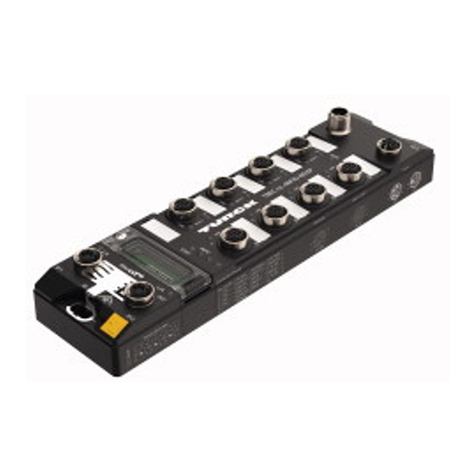
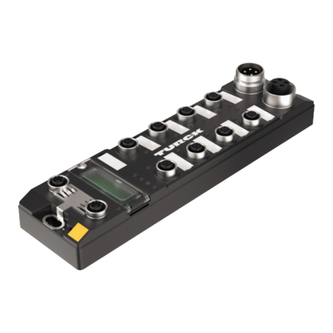
turck TBEN-Lx-8IOL User manual
Other turck Control Unit manuals
turck
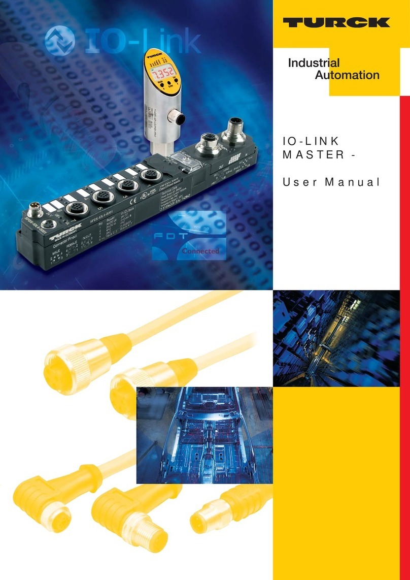
turck IO-LINK MASTER User manual
turck
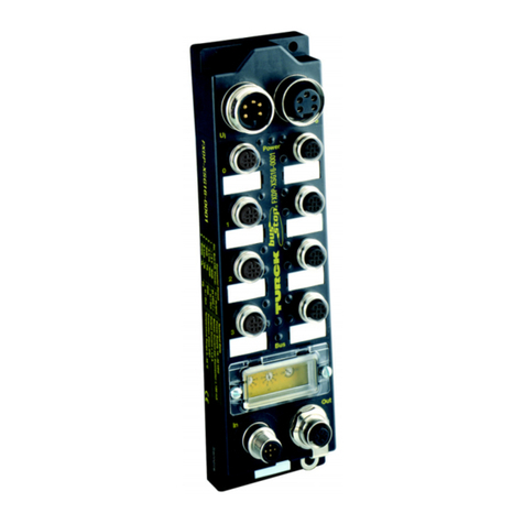
turck FXDP Series User manual
turck
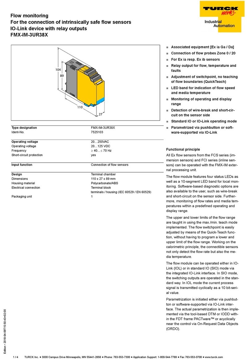
turck FMX-IM-3UR38X User manual
turck
turck TBEN-LH-8IOL User manual
turck
turck IM18-CCM51-12I User manual

turck
turck TBEN-RFID Series Technical manual
turck
turck TBEN-L 8IOL Series User manual
turck
turck TBEN EN1 Series User manual
turck
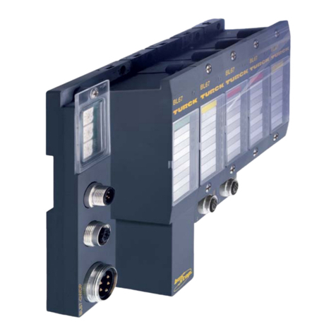
turck BL67 User manual
turck
turck TX-EXTEND User manual
turck
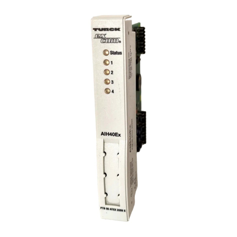
turck excom I/O System Use and care manual
turck
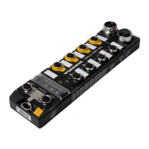
turck TBPN-L1-FDIO1-2IOL User manual

turck
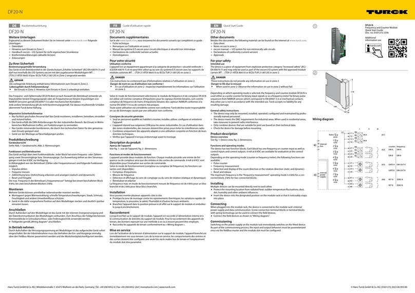
turck TX700 HMI/PLC Series User manual
turck
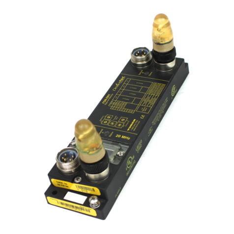
turck DF20-N User manual
turck
turck FDN-DN1 User manual

turck
turck TBEN-S Series User manual
turck
turck excom-RMD1-BU User manual

turck
turck TBEN-LL-8IOL User manual

turck
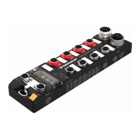
turck TBIP-L 4FDI-4FDX Series User manual
turck
turck TBPN-L FDIO1-2IOL Series User manual
Popular Control Unit manuals by other brands

Festo
Festo Compact Performance CP-FB6-E Brief description

Elo TouchSystems
Elo TouchSystems DMS-SA19P-EXTME Quick installation guide

JS Automation
JS Automation MPC3034A user manual

JAUDT
JAUDT SW GII 6406 Series Translation of the original operating instructions

Spektrum
Spektrum Air Module System manual

BOC Edwards
BOC Edwards Q Series instruction manual

KHADAS
KHADAS BT Magic quick start

Etherma
Etherma eNEXHO-IL Assembly and operating instructions

PMFoundations
PMFoundations Attenuverter Assembly guide

GEA
GEA VARIVENT Operating instruction

Walther Systemtechnik
Walther Systemtechnik VMS-05 Assembly instructions

Altronix
Altronix LINQ8PD Installation and programming manual

