turck NIC EM30-IOL Series User manual

Your Global Automation Partner
Instructions for Use
NIC…-EM30-IOL-…
Inductive Couplers

Contents
Hans Turck GmbH & Co. KG | T +49 208 4952-0 | [email protected] | www.turck.com V01.00 | 2023/03 | 2
Contents
1 About these Instructions ...................................................................................................................4
1.1 Target groups ...................................................................................................................4
1.2 Explanation of symbols used.........................................................................................4
1.3 Other documents.............................................................................................................4
1.4 Feedback about these instructions ..............................................................................4
2 Notes on the product .........................................................................................................................5
2.1 Product identification .....................................................................................................5
2.2 Scope of delivery..............................................................................................................5
2.3 Turck service .....................................................................................................................5
3 For your safety.....................................................................................................................................6
3.1 Intended use .....................................................................................................................6
3.2 General safety instructions ............................................................................................6
4 Product description ............................................................................................................................7
4.1 Device overview...............................................................................................................7
4.2 Properties and features ..................................................................................................7
4.3 Operating principle .........................................................................................................8
4.4 Functions and operating modes...................................................................................8
4.4.1 IO-Link mode......................................................................................................................................8
4.4.2 SIO mode.............................................................................................................................................8
4.4.3 Configuration mode........................................................................................................................8
4.4.4 Foreign object detection (FOD) ..................................................................................................9
4.5 Technical accessories ................................................................................................... 10
5 Installing ............................................................................................................................................ 12
5.1 Angle offset.................................................................................................................... 13
5.2 Lateral offset.................................................................................................................. 13
6 Connection ........................................................................................................................................ 14
6.1 Wiring diagrams............................................................................................................ 14
6.2 IO-Link mode ................................................................................................................. 14
6.3 SIO mode ........................................................................................................................ 14
6.3.1 Digital input..................................................................................................................................... 14
6.3.2 Digital output.................................................................................................................................. 14
7 Commissioning................................................................................................................................. 15
7.1 IO-Link mode ................................................................................................................. 15
8 Operation........................................................................................................................................... 16
8.1 LEDs ................................................................................................................................. 16
8.2 Temperature derating.................................................................................................. 17
8.3 Resetting to factory settings....................................................................................... 17
9 Setting................................................................................................................................................ 18
10 Troubleshooting............................................................................................................................... 19
11 Maintenance ..................................................................................................................................... 20

12 Repair ................................................................................................................................................. 20
12.1 Returning devices ......................................................................................................... 20

Contents
Hans Turck GmbH & Co. KG | T +49 208 4952-0 | [email protected] | www.turck.com V01.00 | 2023/03 | 3
13 Disposal.............................................................................................................................................. 20
14 Technical Data .................................................................................................................................. 21
14.1 Technical data of the primary side ............................................................................ 21
14.2 Technical data of the secondary side........................................................................ 21
14.3 Technical data of inductive transfer system............................................................ 22
14.4 Ambient conditions...................................................................................................... 22
14.5 Design ............................................................................................................................. 22
15 Turck subsidiaries — contact information.................................................................................. 23

About these instructions
Feedback about these instructions
Hans Turck GmbH & Co. KG | T +49 208 4952-0 | [email protected] | www.turck.com V01.00 | 2023/03 | 4
1 About these Instructions
These instructions for use describe the structure, functions and the use of the product and will
help you to operate the product as intended. Read these instructions carefully before using the
product. This is to avoid possible damage to persons, property or the device. Retain the instruc-
tions for future use during the service life of the product. If the product is passed on, pass on
these instructions as well.
1.1 Target groups
These instructions are aimed at qualified personal and must be carefully read by anyone
mounting, commissioning, operating, maintaining, dismantling or disposing of the device.
1.2 Explanation of symbols used
The following symbols are used in these instructions:
DANGER
DANGER indicates a dangerous situation with high risk of death or severe injury if
not avoided.
WARNING
WARNING indicates a dangerous situation with medium risk of death or severe in-
jury if not avoided.
CAUTION
CAUTION indicates a dangerous situation of medium risk which may result in minor
or moderate injury if not avoided.
NOTICE
NOTICE indicates a situation which may lead to property damage if not avoided.
NOTE
NOTE indicates tips, recommendations and useful information on specific actions
and facts. The notes simplify your work and help you to avoid additional work.
uCALL TO ACTION
This symbol denotes actions that the user must carry out.
aRESULTS OF ACTION
This symbol denotes relevant results of actions.
1.3 Other documents
Besides this document the following material can be found on the Internet at www.turck.com:
nData sheet
nDeclarations of Conformity (current version)
nQuick Start Guide
nCommissioning manual IO-Link devices
nApprovals
nIO-Link parameters
1.4 Feedback about these instructions
We make every effort to ensure that these instructions are as informative and as clear as pos-
sible. If you have any suggestions for improving the design or if some information is missing in
the document, please send your suggestions to [email protected].

Notes on the product
Turck service
Hans Turck GmbH & Co. KG | T +49 208 4952-0 | [email protected] | www.turck.com V01.00 | 2023/03 | 5
2 Notes on the product
2.1 Product identification
These instructions apply to the following inductive couplers:
nNICP-EM30-IOL-H1141
nNICS-EM30-IOL-HK1141
NIC P – EM30 – IOL H1141
NIC Functional principle –
Functional principle
NIC Non-flush inductive coupler
IOL IO-Link
IO-Link
IOL IO-Link, COM3
PComponent –
Component
PPrimary side (transmitter)
SSecondary side (receiver)
EM30 Design –
Design
M30 M30 × 1.5, threaded barrel,
stainless steel
H1141 Electrical connection
Electrical connection
H1141 Integrated male
connector M12 × 1, 4-pin
HK1141 Integrated female
connector,
M12 × 1, 5-pin
2.2 Scope of delivery
The scope of delivery includes:
nPrimary side or secondary side
nTwo M30 nuts for mounting
nQuick Start Guide
2.3 Turck service
Turck supports you with your projects, from initial analysis to the commissioning of your applic-
ation. The Turck product database under www.turck.com contains software tools for program-
ming, configuration or commissioning, data sheets and CAD files in numerous export formats.
The contact details of Turck subsidiaries worldwide can be found on p. [}23].

For your safety
General safety instructions
Hans Turck GmbH & Co. KG | T +49 208 4952-0 | [email protected] | www.turck.com V01.00 | 2023/03 | 6
3 For your safety
The product is designed according to state-of-the-art technology. However, residual risks still
exist. Observe the following warnings and safety notices to prevent damage to persons and
property. Turck accepts no liability for damage caused by failure to observe these warning and
safety notices.
3.1 Intended use
Inductive couplers are used in industrial applications for the contactless transfer of energy
(power up to 18W) and for bidirectional data exchange across an air interface (max. 7mm). The
devices consist of a primary side and a secondary side. The primary side supplies power to the
secondary side across an air interface. Both sides supply data from the connected sensors and
actuators.
The devices may only be used as described in these instructions. Any other use is not in accord-
ance with the intended use. Turck accepts no liability for any resulting damage.
3.2 General safety instructions
nThe device may only be assembled, installed, operated, parameterized and maintained by
professionally-trained personnel.
nThe device meets the EMC requirements for industrial areas. When used in residential areas,
take measures to avoid radio interference.
nThe device may only be used in accordance with applicable national and international regu-
lations, standards and laws.
nDo not place any metallic objects in the electrical field between the primary and secondary
side.
nAny extended stay within the electromagnetic field of the inductive couplers may be harm-
ful to the health of persons with active medical implants. Observe a minimum distance of
30cm from the actively radiating surface of the devices.
nThe protective effect of the device can be impaired if the device is used in any way that is not
specified by Turck.

Product description
Properties and features
Hans Turck GmbH & Co. KG | T +49 208 4952-0 | [email protected] | www.turck.com V01.00 | 2023/03 | 7
4 Product description
The devices have a cylindrical design with an M30 × 1.5 male thread. An M12 connector on the
housing is provided to connect the NICP-EM30-IOL-H1141 primary side. The NICS-EM30-IOL-
HK1141 secondary side is provided with an M12 female connector.
4.1 Device overview
mm [Inch]
15.5 [0.61] 55.5 [2.19]
86 [3.39]
Ø 26.5 [1.04]
M30 × 1.5
M12 × 1
36/5
LED
fig.1: NICP-EM30-IOL-H1141 primary side
mm [Inch]
15.5 [0.61] 57.3 [2.26]
86 [3.39]
Ø 26.5 [1.04]
M30 × 1.5
M12 × 1
36/5
LED
fig.2: NICS-EM30-IOL-HK1141 secondary side
4.2 Properties and features
nThreaded barrel, M30 × 1.5
nStainless steel, 1.4404
nDC 4-wire, 24 VDC +20%/-15%

Product description
Functions and operating modes
Hans Turck GmbH & Co. KG | T +49 208 4952-0 | [email protected] | www.turck.com V01.00 | 2023/03 | 8
4.3 Operating principle
Inductive couplers transfer power according to the inductive coupling power transfer (ICPT)
principle. The frequency of the alternating field is 100…148.5kHz. Data is transferred on a car-
rier frequency of 2.4GHz.
C/Q
DO
DC
C/Q
DI
DC
2,4 GHz
ICPT
Signal
processing Near field
DC/AC
converter Power
Signal
processing
Near field
AC/DC
converter
Power
Primary side Secondary side
fig.3: Block diagram
Inductive couplers are used in industrial applications for the contactless transfer of power and
for bidirectional data exchange across an air interface (max. 7mm). The devices consist of a
primary side and a secondary side. The primary side supplies power to the secondary side
across an air interface. Both sides supply data from the connected sensors and actuators.
4.4 Functions and operating modes
The inductive couplers can be operated in IO-Link mode and in SIO mode. In IO-Link mode, the
devices transfer power and IO-Link signals. Either signals from two PNP/NPN inputs or one
PNP/NPN output can be transferred in SIO mode.
4.4.1 IO-Link mode
IO-Link mode enables bidirectional IO-Link communication between an IO-Link master and an
IO-Link device via the air interface.
4.4.2 SIO mode
Standard I/O mode (SIO mode) enables the transfer of the signals of two PNP/NPN inputs or
one PNP/NPN output. The selection of PNP or NPN and input or output is carried out in config-
uration mode. The secondary side with a connected two-way splitter (e.g. VB2-FSM4.4-2FKM4)
transfers two standard PNP/NPN signals to the primary side. The two-way splitter is not re-
quired when using sensors with two outputs (power clamps). The second input or output is de-
activated (pin 2) when using an actuator. The actuator must be connected to pin 4.
4.4.3 Configuration mode
The following modifications can be carried out in configuration mode:
nsetting the inductive coupler system
nreading diagnostic information from the inductive coupler system

Product description
Functions and operating modes
Hans Turck GmbH & Co. KG | T +49 208 4952-0 | [email protected] | www.turck.com V01.00 | 2023/03 | 9
4.4.4 Foreign object detection (FOD)
The foreign object detection (FOD) detects the presence of metal objects between the primary
and secondary side during the power transfer. The power supply of the device is switched off if
the FOD detects foreign objects. The operation of the system is automatically restored as soon
as the primary side no longer detects any metal.
Operating principle of foreign object detection: Power is taken from the coupler system if a
metal object is located in the electromagnetic field between the primary side and the second-
ary side when power is transferred. The coupler system detects the loss in power and interrupts
the power transfer.
Limits of foreign object detection: No foreign object is identified if the loss of power between
the primary side and secondary side is too little. Smaller metal foreign objects such as M2
screws only take a little power from the coupler system and are therefore not detected. The
FOD also does not detect any metal foreign objects if the power transfer between the primary
side and secondary side is negligible.

Product description
Technical accessories
Hans Turck GmbH & Co. KG | T +49 208 4952-0 | [email protected] | www.turck.com V01.00 | 2023/03 | 10
4.5 Technical accessories
Dimension drawing ID Type Description
34.8 [1.37]
Ø 6.3 [0.25]
217.9 [8.58]
230.4 [9.07]
6 [0.24]
60.4 [2.38]
Ø 6.4 [0.25]
30.2 [1.19]
24 [0.95]
X7XF2 X6 X5 X4
X3XF1 X2 X1 X0
XD2
XD1
100003910 TBEN-
LL-8IOL
Compact multiprotocol I/O mod-
ule for Ethernet, 8IO-Link master
channels, 4 universal digital PNP
channels, 2A, channel dia-
gnostics
218
230.5
C4C5C6C7
6.3
38.8
60.4
C0C1C2C3
24
30.2
X2
X1
P2
P1
6814017 TBEN-
L5-8IOL
Compact multiprotocol I/O mod-
ule for Ethernet, 8IO-Link master
channels, 4 universal digital PNP
channels, 2A, channel dia-
gnostics
132
144.3
32
32
C0C1C2C3
24
17.9
28
X2
X1
P2
P1
ø 4.6
6814024 TBEN-
S2-4IOL
Compact multiprotocol I/O mod-
ule for Ethernet, 4IO-Link master
channels, 4 universal digital PNP
channels, 0.5A, channel dia-
gnostics
16 [0.63] 24.9 [0.98]
26.8 [1.06]
31.6 [1.24]
132 [5.20]6.1 [0.24]
144 [5.67]
M12 x 1
Ø 4.3 [0.17]
Ø 4.3 [0.17]
C3P1 C2 C1 C0
100002596 TBIL-S4-8DIP I/O hub to connect digital signals
to IO-Link master, 8 digital in-
puts, 4 M12 ports
C1 C3
C2 C4
C5
C6
C7
C8
73
107
44,7 32,2
150
16 25,2
ø 4,3
54
M12 x 1
27,4
6814102 TBIL-
M1-16DXP
I/O hub for IO-Link, 16 universal
digital PNP channels

Product description
Technical accessories
Hans Turck GmbH & Co. KG | T +49 208 4952-0 | [email protected] | www.turck.com V01.00 | 2023/03 | 11
Dimension drawing ID Type Description
LED
91
32
77,5
195
13
145
6827386 BL67-4IOL IO-Link 1.1 master for BL67 mod-
ular fieldbus system, 4IO-Link
ports and 4programmable PNP
ports
14
42
11.5
ø 15
M12 x 1
L
14 M12 x 1
ø 15
49.5
18.2
6625608 RKC4.4T-2-
RSC4.4T/TXL
Connection cable, M12 female
connector, straight, 4-pin;
M12 male connector, straight,
4-pin; cable material PUR, black,
cable length: 2m
14
42
11.5
ø 15
M12 x 1
L
14 M12 x 1
ø 15
49.5
18.2
6626356 RKS4.4T-2-
RSS4.4T/TXL
Connection cable, M12 female
connector, straight, 4-pin, jacket
material PUR, black,
cable length 2 m
14
17
M12 x 1
M12 x 1
13
23
12.5
19
18
25
3820
ø 4.5
6632239 VB2-
FSM4.4-2FK
M4.4
2-way splitter, Y-splitter without
cable, M12 male connector,
4-pin, 2×M12 female connector,
4-pin, parallel wiring, RoHS com-
pliant, protection type IP67
mm [Inch]
5 mm
1 Nm
30 [1.18]
40 [1.57]
42 [1.65]
59 [2.32]
Ø 30
[1.18]
100047196 BSM-30 Mounting bracket, mounting
accessories for M30×1.5 induct-
ive sensors, in accordance with
DIN 3015-1, consisting of two
half shells, aluminum

Installing
Hans Turck GmbH & Co. KG | T +49 208 4952-0 | [email protected] | www.turck.com V01.00 | 2023/03 | 12
5 Installing
NOTE
Heat buildup
Loss of power due to high device temperature
Install the device in heat conductive material (e.g. mounting clip BSM-30).
Ensure sufficient ventilation and heat dissipation.
The maximum tightening torque of the housing nuts is 40Nm.
Install the device at the intended location. Observe the minimum mounting distances.
Align the front faces of the primary and secondary sides to each other. The maximum dis-
tance between the primary and secondary side is 7 mm.
Refer to tables “Angle offset” and “Lateral offset”.
D
S
T
N
fig.4: Mounting distances
Distance Minimum mounting distances
D 60 mm
N 26.5 mm
S 30 mm
T 60 mm

Installing
Lateral offset
Hans Turck GmbH & Co. KG | T +49 208 4952-0 | [email protected] | www.turck.com V01.00 | 2023/03 | 13
5.1 Angle offset
D
α
fig.5: Angle offset
Distance D Angle α
2 mm 7.5°
4 mm 15°
5 mm 20°
7 mm 30°
5.2 Lateral offset
M
D
fig.6: Lateral offset between primary side (left) and secondary side (right)
Distance D Offset M
0…4 mm 5 mm
5 mm 3 mm
7 mm 2 mm

Connection
SIO mode
Hans Turck GmbH & Co. KG | T +49 208 4952-0 | [email protected] | www.turck.com V01.00 | 2023/03 | 14
6 Connection
Use shielded cables in environments with severe electromagnetic interference.
6.1 Wiring diagrams
3
2
4
1
1
2
4
3
+
–
Input 1/Out 1/IO-Link
Out 2
fig.7: Pin layout of primary side fig.8: Wiring diagram of primary side
4
13
2
5
Input 2
Input 1/Out 1/IO-Link
Reset
1
4
5
2
3
+
–
fig.9: Pin layout of secondary side fig.10: Wiring diagram of secondary side
6.2 IO-Link mode
NOTE
In IO-Link mode, pin 2 cannot be used as a digital input or output.
Connect the NICP… primary side to an IO-Link master via an M12 connection cable (e.g.
RKC4.4T-2-RSC4.4T/TXL) as shown in the wiring diagrams.
Connect the NICS… secondary side via an M12 connection cable to an IO-Link device as
shown in the wiring diagrams.
6.3 SIO mode
6.3.1 Digital input
One sensor: Connect the NICS… secondary side via an M12 connection cable to a sensor
as shown in the wiring diagrams.
Two sensors: Connect the NICS… secondary side via an M12 connection cable to a two-
way splitter (e.g. VB2-FSM4.4-2FKM4) as shown in the wiring diagrams. The two-way split-
ter is not required when using sensors with two outputs (power clamps).
Connect the NICP… primary side via an M12 connection cable to a controller or a field-
bus device as shown in the wiring diagrams.
6.3.2 Digital output
NOTE
When transferring from a digital output, pin 2 cannot be used as a digital input or
output.
Connect the NICS… secondary side output 1 (pin 4) to an actuator via an M12 connection
cable as shown in the wiring diagrams.
Connect the NICP… primary side via an M12 connection cable to a controller or a field-
bus device as shown in the wiring diagrams.

Commissioning
IO-Link mode
Hans Turck GmbH & Co. KG | T +49 208 4952-0 | [email protected] | www.turck.com V01.00 | 2023/03 | 15
7 Commissioning
After the connection is made and the power supply is switched on, the device is operational
after a readiness delay. The readiness delay of the data transfer depends on:
nthe connected devices on the secondary side
nthe set cycle time in the IO-Link master
nthe connection time and connected IO-Link devices, IO-Link master and their parameters
The connection time for the complete system is normally 1400 ms. The following measures can
be taken to reduce the connection time:
nuse of a Turck IO-Link master with the Quick startup switched on: Connection time normally
1100 ms
nPrimary side already switched on: Connection time normally 600ms
7.1 IO-Link mode
Set the cycle time of min. 10 ms on the IO-Link master.
aThe inductive coupler is operational.

Operation
LEDs
Hans Turck GmbH & Co. KG | T +49 208 4952-0 | [email protected] | www.turck.com V01.00 | 2023/03 | 16
8 Operation
CAUTION
The housing gets very hot during operation.
Risk of burning due to hot housing surfaces
Protect the housing from contact with flammable material.
Protect the housing from accidental contact.
Multiple components of the secondary side with the same configuration can be run on one
primary side (dynamic pairing). Process data is delayed by one cycle for each coupler system.
Acyclic data is delayed by two cycles. The time between the coupling operations must be at
least 2 s to ensure a constant startup time.
8.1 LEDs
Primary side Secondary side Meaning
Green Green Operating voltage, SIO mode pin 4
(C/Q) inactive
Orange flashing 5Hz Green Operating voltage, SIO mode pin 4
(C/Q) active or inactive – poor con-
nection quality
Green flashing 0.5 Hz Off No secondary side coupled
Green flashing 1 s on, 0.1 s
off
Green flashing 1s on, 0.1s
off
IO-Link communication with connec-
ted device
Green Red IO-Link master connected, but no
IO-Link communication with device
on the secondary side
Orange Orange SIO mode pin 4 (C/Q) active
Orange flashing 1Hz Off Foreign object detection (FOD)
active
Orange/green alternately
1Hz
Orange/green alternately
1Hz
Configuration mode
Red flashing 5 Hz Off Primary side error
Secondary side red flashing (5Hz), behavior of the
primary side not relevant
Secondary side error

Operation
Resetting to factory settings
Hans Turck GmbH & Co. KG | T +49 208 4952-0 | [email protected] | www.turck.com V01.00 | 2023/03 | 17
8.2 Temperature derating
Derating is required at temperatures above 45°C.
POut/W
18
T/ C
12
6
05545
-25 -15 -5 5 15 25 35
0
fig.11: Temperature derating
8.3 Resetting to factory settings
The inductive coupler can be reset in configuration mode to the factory settings. Alternative
manual reset:
Switch on the primary side power supply.
Connect pin 5 of the secondary side with pin 4.
Align the secondary side with the primary side (see [}12]).
aThe factory settings are restored.
Without dynamic pairing:
Switch on the primary side power supply.
Connect pin 5 of the secondary side with GND of the secondary side.
Align the secondary side with the primary side (see [}12]).
aThe factory settings are restored.

Setting
Hans Turck GmbH & Co. KG | T +49 208 4952-0 | [email protected] | www.turck.com V01.00 | 2023/03 | 18
9 Setting
The device can be parameterized via IO-Link. The following steps are required to switch the sys-
tem to the configuration mode:
An IO-Link device with a freely writable Application Specific Tag must be connected to
the secondary side.
The inductive couplers must be in the coupled state.
Write _EnterConfigMode in the Application Specific Tag. Observe upper and lower case.
Use the IODD of the inductive coupler for the port.
aThe connection to the IO-Link device is interrupted.
aThe inductive coupler system is operated as an IO-Link device.
Close configuration mode:
Write _LeaveConfigMode in the Application Specific Tag. Observe upper and lower case.
or
Carry out a voltage reset.

Troubleshooting
Hans Turck GmbH & Co. KG | T +49 208 4952-0 | [email protected] | www.turck.com V01.00 | 2023/03 | 19
10 Troubleshooting
The device is provided with Foreign Object Detection (FOD). The FOD detects metal objects in
the active area between the primary and secondary side. If an object is detected, the device
switches off the power supply automatically. The LED of the primary side is flashing orange if
the FOD is active.
CAUTION
Heated metal parts in the active area
Risk of burning
Wear safety gloves when removing foreign objects.
Remove foreign objects from the active area.
aThe device returns automatically to operating mode.

Maintenance
Returning devices
Hans Turck GmbH & Co. KG | T +49 208 4952-0 | [email protected] | www.turck.com V01.00 | 2023/03 | 20
11 Maintenance
Ensure that the plug connections and cables are always in good condition.
The devices are maintenance-free, clean dry if required.
The active area between the primary and secondary side must occasionally be cleared of metal
contamination (e.g. metal chippings) in order to maintain correct operation.
12 Repair
The device must not be repaired by the user. The device must be decommissioned if it is faulty.
Observe our return acceptance conditions when returning the device to Turck.
12.1 Returning devices
Returns to Turck can only be accepted if the device has been equipped with a Decontamination
declaration enclosed. The decontamination declaration can be downloaded from
https://www.turck.de/en/retoure-service-6079.php
and must be completely filled in, and affixed securely and weather-proof to the outside of the
packaging.
13 Disposal
The devices must be disposed of properly and do not belong in the domestic waste.
This manual suits for next models
2
Table of contents
Other turck Industrial Equipment manuals

turck
turck BL ident TW-R16-B128-Ex User manual

turck
turck M12-AO01 Series User manual

turck
turck PK01VR P Series User manual

turck
turck IMXK12-DO01 Series User manual

turck
turck SC11-3G User manual

turck
turck DI80-N User manual

turck
turck RA-SAB-15-36 User manual

turck
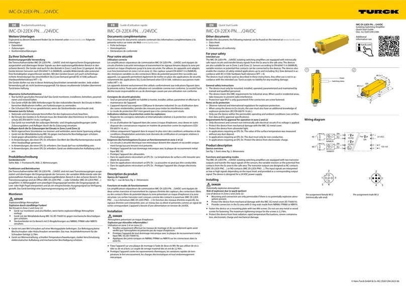
turck IMC-DI-22EX-PN 24VDC Series User manual

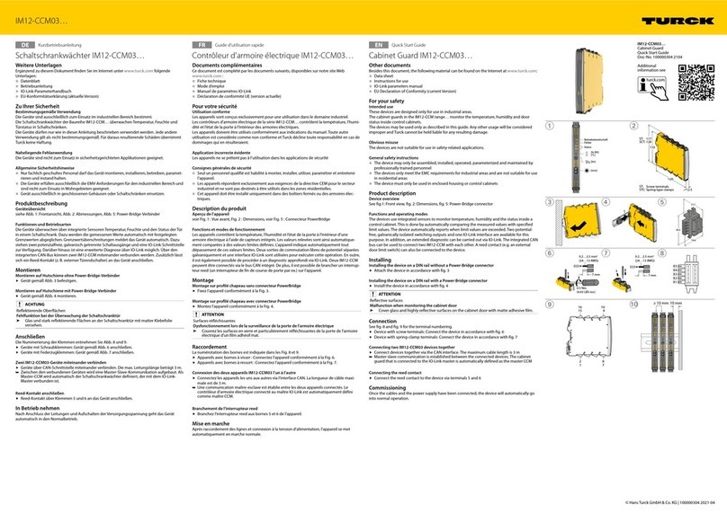
turck
turck IM12-CCM03 Series User manual

turck
turck EZ-track LT Q35 Series User manual