4 Turck Inc. |3000 Campus Drive, Minneapolis, MN 55441 |T +1 800 544 7769 |F +1 763 553 0708 |www.turck.com
Functional Overview
Mounting Instructions
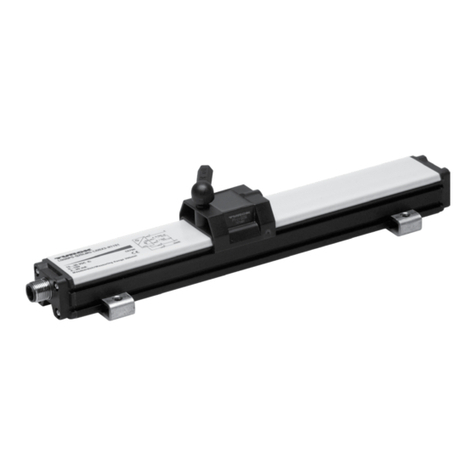
The transducer can be mounted vertically or horizontally using MB-Q21 Mounting Brackets. The mounting brackets slide in
the grooves on the lower part of the extrusion and clamp down when tightened. It is recommended to use one mounting
bracket on each end and every three feet between. Ferro-magnetic material, (material readily magnetized) should be placed
no closer than .25 inches from the sensing surface of the LDT.
NOTE:
If using the oating magnet option, you must set the automatic gain control.
Automatic Gain Control (AGC)
The Automatic Gain Control feature is only used when sensing a magnet other than the standard SM-Q21 Slide Magnet. If you
are using the standard slide magnet skip to Setting ZERO and SPAN Position.
When using the Floating Magnet assembly FM-Q21, the magnet should be installed within .375 inches (9.53 mm) of the
sensing surface. The magnet assembly should also be installed in such a manner that it remains an even distance from the
aluminum extrusion throughout the entire stroke. Improperly installed magnets can result in output signal non-linearity.
NOTE:
The north pole of the magnet should be pointed towards the probe.
To set the Automatic Gain Control (AGC) level for the probe, follow these steps:
1. Place magnet assembly close to the dead zone (but within the active region) of the probe.
2. Power down the probe.
3. Short program pin (pin 2) to ground (pin 3).
NOTE:
When the probe is in AGC mode, the output will be either 0 volts or 4 mA, depending on the model that was ordered.
4. Apply power to probe:
a. The LED ashes RED indicating it is in the AGC mode.
b. The LED will change to ashing GREEN when it has determined the proper AGC level and has saved it to
non-volatile memory.
The AGC is now complete.
To place the probe back into the normal operating mode, follow these steps:
1. Power down the probe.
2. Remove short from program pin.
3. Apply power to the probe.
Setting ZERO and SPAN Position
The Q21 Series is programmable over the entire active stroke length of the LDT. Keep in mind, there is a 3 inch Null area at the
connector end of the LDT, and a 1.5 inch Dead area at the other end of the LDT where the magnet cannot be detected. The
diagnostic LED can aid you in the setup of the ZERO and SPAN. A green or yellow LED means that the LDT can be programmed
in this area, a red LED means that the LDT cannot be programmed in this area. To set the ZERO and SPAN position for the
probe, follow these steps:
1. Power up the probe in normal operating mode (i.e. program pin oating).
2. Place magnet assembly where ZERO is to be located but within the active region of the probe.
3. Momentarily short program pin (pin 2) to ground (pin 3).
4. Place magnet assembly where SPAN is to be located but within the active region of the probe.
5. Momentarily short program pin (pin 2) to V+ (pin 1).
NOTE:
A. AGC should be set rst before setting the ZERO and SPAN positions when using a oating magnet
B. SPAN could also be set rst, followed by setting the ZERO position
C. ZERO and SPAN can be adjusted individually without setting the other
D. ZERO = 0 V on 0 to 10 VDC units, -10 V on -10 to 10 VDC units, and 4 mA on 4 to 20 mA units
