manuals.online logo
Brands
  1. Home
  2. •
  3. Brands
  4. •
  5. turck
  6. •
  7. Transducer
  8. •
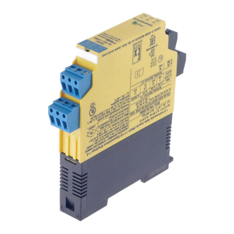
  9. turck interface modul IM33-FSD-Ex/L User manual

turck interface modul IM33-FSD-Ex/L User manual

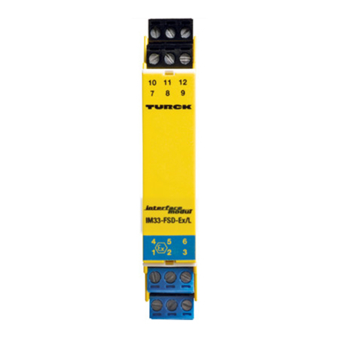
Messumformer-
Speisetrenner
IM33-FSD-Ex/L
Gerätekurzbeschreibung
• Messumformer-Speisetrenner ohne
Hilfsenergie (loop-powered)
• Versorgung von Brand- und Rauchmeldern
• Signalübertragung 0...50 mA
• Kurzschlussstrom < 100 mA
• Eingangskreise eigensicher
II (1) GD [EEx ia] IIC
• Zweikanalig
• Allseitige galvanische Trennung
• Verpolgeschützte Anschlüsse
• Abziehbare Klemmenblöcke
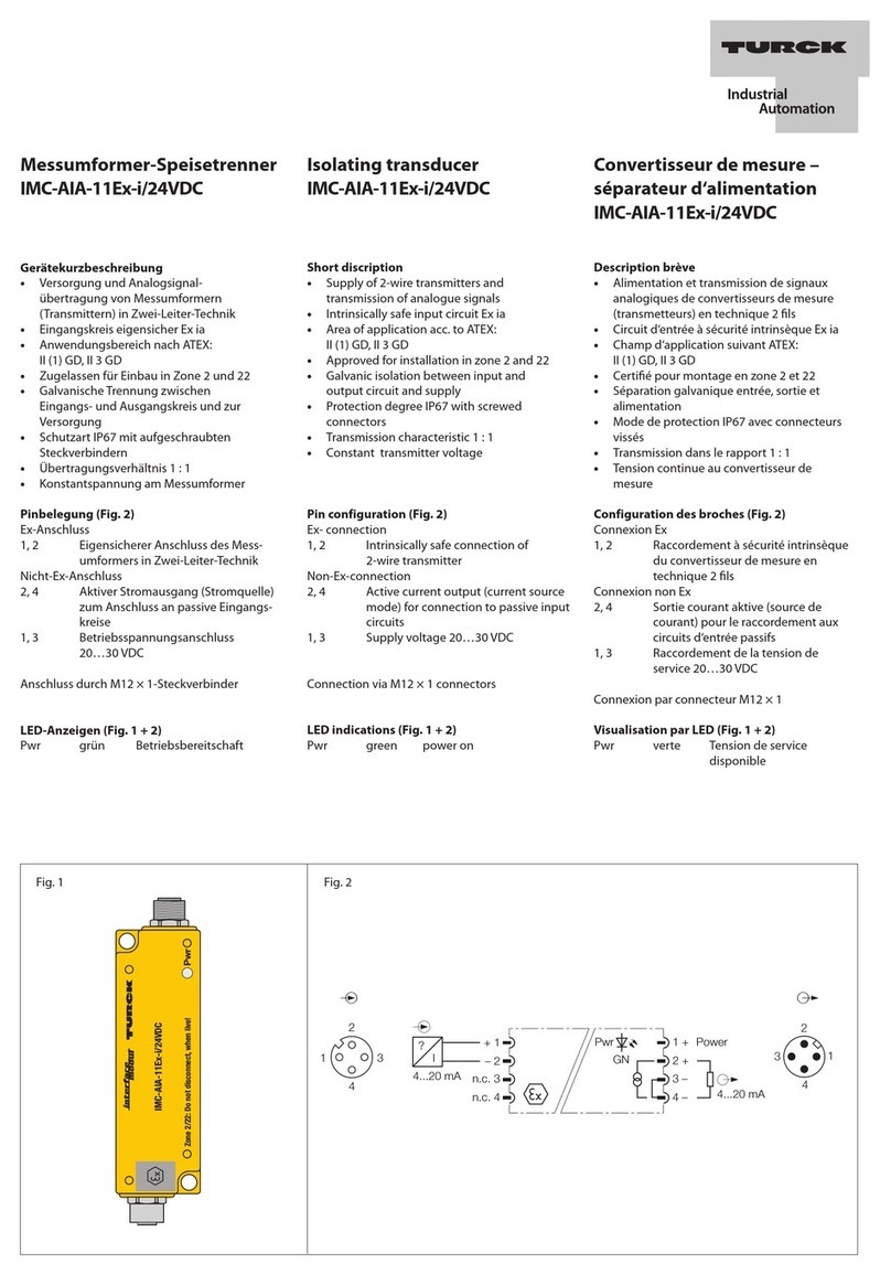
Klemmenbelegung (Fig. 2)
1, 2 Anschluss eigensicherer Melderkreis 1
3 Eigensicherer Anschluss für Erd-
schlusswächter Kreis 1
4, 5 Anschluss eigensicherer Melderkreis 2
6 Eigensicherer Anschluss für Erd-
schlusswächter Kreis 2
8, 9 Anschluss für Auswerteeinrichtung mit
aktiven Eingängen, Kreis 2
11, 12 Anschluss für Auswerteeinrichtung mit
aktiven Eingängen, Kreis 1
Anschluss durch Flachklemmen mit selbstab-
hebenden Andruckscheiben, Anschlussquer-
schnitt ≤1 x 2,5 mm2, 2 x 1,5 mm2oder
2 x 1,0 mm2mit Aderendhülsen
Fig. 1 Fig. 2
IM33-FSD-Ex/L
978
1210 11
3
6
5
12
4
 1
+ 2
11 
12 +
3
 4
+ 5
6
8 
9 +
I
I
1
2
1
2
mA
mA
I
I
I
I
UPwr < 35 V
UPwr < 35 V
IA
IA
UD
UD
Short description
• The isolating transducer operates without
auxiliary power (loop-powered)
• Supply of fire and smoke alarms
• 0...50 mA signal transfer
• Short circuit current < 100 mA
• Intrinsically safe input circuits
II (1) GD [EEx ia] IIC
• Two channels
• Complete galvanic isolation
• Reverse polarity protected connections
• Removable terminal blocks
Terminal configuration (Fig. 2)
1, 2 Connection of intrinsically safe alarm
circuit 1
3 Intrinsically safe connection of current-
to-ground detection circuit 1
4, 5 Connection of intrinsically safe alarm
circuit 2
6 Intrinsically safe connection of current-
to-ground detection circuit 2
8,9 Connection of processor unit with
active inputs, circuit 2
11, 12 Connection of processor unit with
active inputs, circuit 1
Connection via flat terminals with self-lifting
pressure plates, connection profile
≤1 x 2.5 mm2, 2 x 1.5 mm2or 2 x 1.0 mm2
with wire sleeves
Isolating Measuring
Transducer
IM33-FSD-Ex/L
Convertisseur de mesure-
séparateur d'alimentation
IM33-FSD-Ex/L
Description brève
• Convertisseur de mesure-séparateur
d'alimentation sans énergie auxiliaire
(loop-powered)
• Alimentation de détecteurs d'incendie
et de fumée
• Transmission des signaux 0...50 mA
• Courant de court-circuit < 100 mA
• Circuits d'entrée à sécurité intrinsèque
II (1) GD [EEx ia] IIC
• Deux canaux
• Séparation galvanique entrée, sortie et
alimentation
• Connexions protégées contre les inversions
de polarité
• Borniers débrochables
Raccordement des bornes (Fig. 2)
1, 2 Raccordement du circuit d'alarme 1
à sécurité intrinsèque
3 Raccordement à sécurité intrinsèque du
circuit 1 du contrôleur de court-circuit à
la terre
4, 5 Raccordement du circuit d'alarme 2
à sécurité intrinsèque
6 Raccordement à sécurité intrinsèque du
circuit 2 du contrôleur de court-circuit à
la terre
8,9 Raccordement de l'appareil de
traitement à entrées actives, circuit 2
11, 12 Raccordement de l'appareil de
traitement à entrées actives, circuit 1
Raccordement par cosses planes avec ron-
delles à poussoir à dégagement automatique,
section raccordable ≤1 x 2,5 mm²,
2 x 1,5 mm² ou 2 x 1,0 mm2 avec cosses.
IM33-FSD-Ex/L
Hinweise
Der Messumformer-Speisetrenner benötigt
keine Hilfsenergie. Die Hilfsenergie wird aus
dem aktiven Eingangskreis der Auswerteein-
richtung entnommen. Dabei ist der Spannungs-
abfall über den Messumformer-Speisetrenner
zu beachten, so dass die angeschlossenen
Melder nicht unter ihrer Mindestbetriebs-
spannung betrieben werden:
UD= UPwr – 1 V – 300 Ω* IA
Die Spannung an den aktiven Eingängen
der Auswerteeinrichtung darf max. 35 VDC
betragen.
Abhängig vom System der Brand- und Rauch-
melder und der Auswerteeinrichtung muss ggf.
ein Abschlusswiderstand angeschlossen
werden. Beachten Sie hierzu die Anleitungen
der anderen Geräte.
An einem eigensicheren Melderkreis dürfen
mehrere Brand- und Rauchmelder angeschlos-
sen werden, sofern der „Nachweis der
Eigensicherheit“ dies zulässt.
Beim Betrieb mit einem Erdschlusswächter
kann es zu einer Welligkeit des Stromsignals
kommen. Um die galvanische Trennung der
beiden Kanäle aufrecht zu erhalten, sind für
jeden Kreis separate Erdschlusswächter erfor-
derlich. Auch hier ist der „Nachweis der Eigen-
sicherheit“ zu führen.
Montage und Installation
(Fig. 3)
Das Gerät ist aufschnappbar auf Hutschiene
(EN 50022) oder aufschraubbar auf Montage-
platte. Geräte gleichen Typs können direkt
aneinander gesetzt werden. Für eine ausrei-
chende Wärmeabfuhr ist zu sorgen.
Montage und Installation sind den gültigen
Vorschriften entsprechend durchzuführen, für
deren Einhaltung der Betreiber verantwortlich
ist.
Die Geräte sind in Schutzart IP20 gemäß
EN 60529 in trockenen, sauberen und gut
überwachten geschlossenen Betriebsräumen,
Gehäusen oder Schränken zu installieren.
Die abziehbaren Klemmenblöcke sind codiert
und können nur auf den vorgesehenen
Sockel gesteckt werden, wobei die Ex-
Klemmen die gleiche Codierung aufweisen.
Die Codierung darf nicht verändert oder
beschädigt werden.
Das Gerät ist ausreichend zu schützen gegen
Staub, Schmutz, Feuchtigkeit und andere
Umwelteinflüsse sowie gegen energiereiche
Strahlung, Risiken mechanischer Beschädi-
gung, unbefugter Veränderung und zufälliger
Berührung. Sämtliche Installationen sind EMV-
gerecht durchzuführen.
Notes
The isolating transducer does not require
auxiliary power. The device is powered via the
active input circuit of the processor unit. Please
note that there is a voltage drop over the
isolating transducer and ensure that the
connected alarm devices are not operated
below their minimum voltage ratings:
UD= UPwr – 1 V – 300 Ω* IA
The voltage at the active inputs of the
processor unit may not exceed 35 VDC.
Depending on the type of smoke and fire
alarm system and the processor unit, it may be
necessary to connect a terminating resistor.
Please observe the respective manuals of the
other devices.
It is admissible to connect several fire and
smoke detectors to an intrinsically safe alarm
circuit, provided the ”Certificate of Intrinsic
Safety” permits this.
When operating a current-to-ground detector,
current ripple may occur. In order to retain
galvanic isolation of the two channels, it is
required to operate separate current-to-ground
detectors for each circuit. This assembly must
also be approved by the ”Certificate of Intrinsic
Safety”.
Mounting and installation
(Fig. 3)
The device is suited for snap-on clamps for
hat rail mounting (EN 50022) or for screw
panel mounting. Devices of the same type
may be mounted directly next to each other. It
must be ensured that heat is conducted away
from the device. Mounting and installation must
be carried out in accordance with the applica-
ble regulations. The operator is responsible for
compliance with the regulations.
According to EN 60529 devices with IP20
protection rating must be installed in dry, clean
and sufficiently monitored closed operating
areas, mounting enclosures and mounting
cabinets.
The removeable terminal blocks are coded
and may only be plugged into the designated
sockets. The Ex terminals have the same
coding. The coding system may not be altered
or damaged.
The device must be protected against dust, dirt,
moisture and other environmental influences as
well as against strong electro-magnetic
emissions. It should also be protected against
the risks of mechanical damaging, unautho-
rised access and incidental contact.
All installations must be carried out observing
the regulations of EMC protection.
Indications
Le convertisseur de mesure-séparateur
d'alimentation n'exige pas d'énergie auxiliaire.
L'appareil est alimenté par le circuit d'entrée
actif de l'appareil de traitement. Veuillez tenir
compte d'une chute de tension par le
convertisseur de mesure-séparateur
d'alimentation, et assurer que les appareils
d'alarme raccordés ne fonctionnent pas en
dessous de leur tension de service min.:
UD= UPwr – 1 V – 300 Ω* IA
La tension aux entrées actives de l'appareil de
traitement ne peut pas dépasser 35 VDC.
Dépendant du système de détection d'incendie
et de fumée et de l'appareil de traitement le
raccordement d'une résistance de fin de ligne
peut s'imposer. Veuillez observer les manuels
des autres appareils.
Il est permis de raccorder plusieurs détecteurs
d'incendie et de fumée, à condition que "la
preuve de la sécurité intrinsèque" l'autorise.
En cas de fonctionnement avec un contrôleur
de court-circuit à la terre une ondulation du
signal de courant peut se présenter. Pour
conserver la séparation galvanique des deux
canaux, chaque circuit nécessite des
contrôleurs de court-circuit à la terre séparés.
"La preuve de la sécurité intrinsèque" doit
également être soumise.
Montage et installation
(Fig. 3)
L‘appareil est encliquetable sur rail symétrique
(EN 50022) ou peut être monté sur panneaux.
Les appareils du même type peuvent être
montés directement l‘un après l‘autre. Une
évacuation suffisante de la chaleur est néces-
saire. Le montage et l’installation doivent être
effectués conformément aux prescriptions
locales valables, dont le respect est la respon-
sabilité de l’exploitant.
Les appareils en mode de protection IP20
doivent être installés conformément à la
norme EN 60529 dans des locaux, boîtiers ou
armoires secs, propres, bien surveillés et
fermés.
Les blocs de bornes débrochables sont codés
et peuvent seulement être enfichés sur le
socle prévu. Les bornes Ex indiquent le même
codage. Il n'est pas permis de modifier ou
d'endommager le codage.
L‘appareil doit être suffisamment protégé
contre les poussières, la pollution, l‘humidité
et les autres influences d‘environnement, ainsi
que contre le rayonnement à grande énergie,
les risques de dommages mécaniques, la
modification non-autorisée et les contacts
accidentels. Toutes les installations doivent être
effectuées conformément à la CEM.
IM33-FSD-Ex/L
Allgemeine Informationen zum Einsatz von
Geräten mit eigensicheren Stromkreisen
Das vorliegende Gerät verfügt an den blau ge-
kennzeichneten Klemmen 1 – 6 über Stromkreise
der Zündschutzart „Eigensicherheit“ für den
Explosionsschutz gemäß EN 50020. Die eigen-
sicheren Stromkreise sind von autorisierten
Prüfungsstellen bescheinigt und für die Verwen-
dung in den jeweiligen Ländern zugelassen.
Für den bestimmungsgemäßen Betrieb in
explosionsgefährdeten Bereichen sind die
nationalen Vorschriften und Bestimmungen
unbedingt zu beachten und einzuhalten.
Nachfolgend werden einige Hinweise gegeben,
insbesondere hinsichtlich der Rahmen-Richtlinie
der Europäischen Union 94/9/EG (ATEX 100a).
Das vorliegende Gerät ist ein zugehöriges Be-
triebsmittel, das neben eigensicheren auch über
nichteigensichere Stromkreise verfügt und daher
nicht im Ex-Bereich installiert werden darf. An die
eigensicheren Anschlüsse können eigensichere
elektrische Betriebsmittel angeschlossen werden.
Alle Betriebsmittel müssen die Voraussetzungen
zum Betrieb in der vorhandenen Zone des
explosionsgefährdeten Bereiches erfüllen.
Bei der Zusammenschaltung von Betriebsmitteln
muss der „Nachweis der Eigensicherheit“ durch-
geführt werden (EN 60079-14). Bereits durch den
einmaligen Anschluss von eigensicheren Strom-
kreisen an nichteigensichere Kreise ist eine spätere
Verwendung als Betriebsmittel mit eigensicheren
Stromkreisen nicht mehr zulässig.
Für die Errichtung eigensicherer Stromkreise, die
Montage an äußeren Anschlussteilen sowie für die
Beschaffenheit und Verlegung von Leitungen gelten
einschlägige Vorschriften. Leitungen und Klemmen
mit eigensicheren Stromkreisen sind zu kenn-
zeichnen und von nichteigensicheren Stromkreisen
zu trennen oder müssen eine entsprechende
Isolierung aufweisen (EN 60079-14).
Von den eigensicheren Anschlüssen dieses Gerä-
tes ist der vorgeschriebene Abstand zu geerdeten
Bauteilen und Anschlüssen anderer Geräte einzu-
halten. Soweit nicht ausdrücklich in der geräte-
spezifischen Anleitung angegeben, erlischt die
Zulassung durch Öffnung des Gerätes, Repara-
turen oder Eingriffe am Gerät, die nicht vom Sach-
verständigen oder Hersteller ausgeführt werden.
Sichtbare Veränderungen am Gerätegehäuse
(z. B. bräunlich-schwarze Verfärbungen durch
Wärme sowie Löcher oder Ausbeulungen) weisen
auf einen schwerwiegenden Fehler hin, worauf
das Gerät unverzüglich abzuschalten ist. Bei
zugehörigen Betriebsmitteln sind die angeschlos-
senen eigensicheren Betriebsmittel ebenfalls zu
überprüfen. Die Überprüfung eines Gerätes hin-
sichtlich des Explosionsschutzes kann nur von
einem Sachverständigen oder vom Hersteller
vorgenommen werden.
Der Betrieb des Gerätes ist nur im Rahmen der
seitlich auf das Gehäuse gedruckten zulässigen
Daten gestattet. Vor jeder Inbetriebnahme oder
nach Änderung der Geräte-Zusammenschaltung
ist sicherzustellen, dass die zutreffenden
Bestimmungen, Vorschriften und Rahmenbedin-
gungen eingehalten werden, ein bestimmungsge-
mäßer Betrieb gegeben ist und die Sicherheits-
bestimmungen erfüllt sind.
Die Montage und der Anschluss des Gerätes ist
von geschultem und qualifiziertem Personal mit
Kenntnis der einschlägigen nationalen und anzu-
wendenden internationalen Vorschriften über den
Ex-Schutz durchzuführen.
Die wichtigsten Daten aus der EG-Bau-
musterprüfbescheinigung sind umseitig
aufgeführt. Alle gültigen nationalen und internatio-
nalen Bescheinigungen der TURCK-Geräte finden
Sie im Internet (www.turck.com).
Weitere Informationen zum Ex-Schutz stellen wir
Ihnen auf Anfrage gern zur Verfügung.
General information on use of devices with
intrinsically safe circuits
This device is equipped with circuits featuring
protection type „intrinsic safety“ for explosion
protection per EN 50020 at terminals 1– 6 which
are marked in blue. The intrinsically safe circuits
are approved by the according authorised bodies
for use in those countries to which the approval
applies.
For correct usage in explosion hazardous areas
it is required to observe and follow the national
regulations and directives strictly.
Following please find some guidelines which refer
to the framework directive of the European Union
94/9/EC (ATEX 100a).
This device is classified as associated apparatus
which is equipped with intrinsically safe and non-
intrinsically safe circuits. Therefore it may not be
installed in explosion hazardous areas. It is
permitted to connect intrinsically safe equipment
to the intrinsically safe connections of this device,
provided the equipment complies with the
regulations applying to use in the respective zone
of the explosion hazardous area.
When interconnecting devices within such an
assembly it is required to verify and certify intrinsic
safety (EN 60079-14).
Once that intrinsically safe circuits have been
connected to the non-intrinsically safe circuit, it is
not permitted to use the device subsequently as
intrinsically safe equipment.
The governing regulations cover installation of
intrinsically safe circuits, mounting to external
connections, cable characteristics and cable
installation. Cables and terminals with intrinsically
safe circuits must be marked and separated from
non-intrinsically safe circuits or feature appropriate
isolation (EN 60079-14).
It is required to observe the specified clearances
between the intrinsically safe connections of this
device and the earthed components and
connections of other devices.
The approval expires if the device is repaired,
modified or opened by a person other than the
manufacturer or an expert, unless the device-
specific instruction manual explicitly permits such
interventions.
Visible damages of the device’s housing (e. g.
black-brown discolouration due to heat
accumulation, perforation or deformation) indicate
a serious error so that the device must be turned
off immediately. When using associated apparatus
it is required to also check the connected intrinsi-
cally safe equipment. This inspection may only be
carried out by an expert or the manufacturer.
Operation of the device must conform to the data
printed on the side of the housing.
Prior to initial set-up or after every alteration of the
interconnection assembly it must be assured that
the relevant regulations, directives and framework
regulations are observed, that operation is error-
free and that all safety regulations are fulfilled.
Mounting and connection of the device should
only be carried out by qualified and trained staff
familiar with the relevant national and international
regulations of explosion protection.
The most important data from the EC type
examination certificate are listed overleaf. All
valid national and international approvals covering
Turck devices are obtainable via the Internet
(www.turck.com).
Further information on explosion protection is
available on request.
Informations générales sur l‘utilisation
d‘appa-reils avec des circuits de courant à
sécurité intrinsèque
Cet appareil est équipé aux bornes bleues 1 – 6
de circuits de courant en mode de protection
„sécurité intrinsèque“ pour la protection contre les
explosions suivant EN 50020. Les circuits de
courant à sécurité intrinsèque disposent d‘un
certificat accordé par les laboratoires agréés et sont
permis pour l‘utilisation dans les pays concernés.
Son fonctionnement conformément aux
dispositions dans les atmosphères explosives
implique le respect des prescriptions et
dispositions nationales.
Ci-dessous sont énumérés quelques conseils,
particulièrement concernant la directive-cadre de
l‘Union européenne 94/9/EC (ATEX 100a).
Cet appareil est du matériel électrique équipé non
seulement de circuits de courant à sécurité
intrinsèque, mais aussi de circuits de courant non
à sécurité intrinsèque et ne peut, par conséquent,
pas être installé dans la zone Ex. Du matériel
électrique à sécurité intrinsèque peut être raccordé
aux connexions à sécurité intrinsèque à condition
que ce matériel électrique à sécurité intrinsèque
remplisse les exigences pour le fonctionnement
dans la zone actuelle de la zone explosible.
En cas d‘interconnexion de matériels électriques la
„preuve de la sécurité intrinsèque“ doit être remplie
(EN 60079-14). Même le raccordement unique de
circuits de courant à sécurité intrinsèque à des
circuits non à sécurité intrinsèque ne permet plus
un fonctionnement ultérieur comme matériel
électrique à sécurité intrinsèque.
Pour la réalisation de circuits de courant à sécurité
intrinsèque, le montage à des pièces de
raccordement extérieures, ainsi que pour la qualité
et le cheminement des conducteurs les
prescriptions concernées sont à respecter. Les
conducteurs et les bornes avec des circuits de
courant à sécurité intrinsèque doivent être
désignés et séparés des circuits de courant non à
sécurité intrinsèque ou doivent être équipés d‘une
isolation appropriée (EN 60079-14).
Quant aux raccordements à sécurité intrinsèque de
cet appareil, la distance prescrite entre les
composants mis à la terre et les raccordements
d‘autres appareils est à respecter.
Sauf s‘il est indiqué dans le mode d‘emploi
spécifique de l‘appareil, l‘homologation n‘est plus
valable en cas d‘ouverture de l‘appareil, ou si des
réparations ou des interventions sont effectuées à
l‘appareil par des personnes autres que des
spécialistes ou que le fabricant.
Des transformations visibles au boîtier de
l‘appareil (p.ex. des décolorations brunâtres noires
par la chaleur ainsi que des trous ou des
gonflements) indiquent un défaut grave impliquant
la désactivation immédiate de l‘appareil.
Quant au matériel électrique associé, le matériel
électrique à sécurité intrinsèque raccordé doit
également être contrôlé. Le contrôle d‘un appareil
en ce qui concerne la protection contre les
explosions ne peut être effectué que par un
spécialiste ou le fabricant. Le fonctionnement de
l‘appareil doit être conforme aux données
imprimées sur le côté de l‘appareil.
Avant toute mise en service ou après modification
de l‘interconnexion des appareils, on doit veiller à
ce que les dispositions, les prescriptions et les
conditions-cadre concernées sont respectées, que
le fonctionnement est conforme aux dispostions et
que les dispositions de sécurité sont remplies.
Le montage et le raccordement de l‘appareil ne
peut être effectué que par des personnes
qualifiées qui sont au courant des prescriptions
nationales et internationales sur la protection Ex
concernées.
Les données essentielles de l‘attestation
d‘examen CE figurent au verso. L‘ensemble des
certificats nationaux et internationaux des appareils
TURCK peuvent être obtenus par internet
(www.turck.com). Plus d’informations sur la
protection Ex peuvent être obtenues sur demande.
D200531 0603 *D200531ßß0603*
EG-Baumusterprüfbescheinigung
EC-Type examination certificate
Attestation d’examen CE de type
II (1) GD [EEx ia] IIC
0102
Fig. 3
Nr./No. TÜV 02 ATEX 1862
U027,3 V
I090 mA
P0615 mW
Kennlinie: linear/characteristic curve: linear/courbe caractéristique: linéaire
L0/C0
– [EEx ia] IIB 5 mH/300 nF
– [EEx ia] IIC 1 mH/70 nF
Um250 VAC/125 VDC
Ta-25...+70 °C
35
110
18
ø 4,5
89
100
92
104
EN 50 022
RUS
GR
NL
DK
I
S
Denna utrustning egensäkra kretsar, för
explosionsskydd enligt EN 50020. Dessa kretsar är
terminalerna 1- 6 och är blåmarkerade. Nationella
regler och bestämmelser för använding inom Ex-
område måste följas. Utrustningen klassas som
tillbehör och får ej monteras i explosionsfarliga
utrymmen. Alla nationella och internationella
certifikat kan tas hem via Internet.
P
E
Este equipamento tem circuitos de segurança intríseca
nos terminais 1-6 (azul) de acordo com as protecções
à explosão das normas EN50020.
É necessário seguir os regulamentos e directivas
nacionais para uma correcta operação nas áreas
explosivas. Este equipamento está classificado como
aparelho associado e pode não estar instalado numa
área explosiva. Todas as aprovações nacionais e
internacionais podem ser vistas na internet.
Det foreliggende apparat indeholder klemmer 1-6 (blå)
med strømkredse af beskyttelsesklasse ”egensikkerhed”
for eksplosionsbeskyttelse iht. EN50020. Til den
forcskrevne drift i eksplosionsfarlige områder, skal de
nationale foreskrifter og bestemmelser ubetinget
iagttages og overholdes. Apparatet er klassificeret som
et tilhørende apparat og må ikke installeres i Ex-
området. Alle nationale og internationale godkendelser
er lagt på internettet.
Dit apparaat beschikt aan de klemmen 1-6 (blauw)
over stroomkringen in de beschermingswijze „Intrinsiek
veilig“ voor de explosiebeveiliging volgens EN 50020.
Voor correct gebruik in ontploffings-gevaarlijke
atmosferen moeten de nationale voorschriften en
bepalingen onvoorwaardelijk gerespecteerd worden.
Het apparaat is bijhorend elektrisch materieel en mag
niet in de Ex-atmosfeer worden geïnstalleerd. Alle
nationale en internationale certificaten kunnen via
internet opgevraagd worden.
Questa unità dispone di circuiti a sicurezza intrinseca
tra i terminali 1-6 (azzurro) in accordo alle norme di
protezione alle esplosioni EN 50020. E‘ necessario
seguire le normative e direttive nazionali per una
corretta applicazione in aree a rischio di esplosione .
Questa unità è classificata come apparato associato e
non può essere installato in aree pericolose. Tutte le
approvazioni nazionali e internazionali possono essere
richiamate via Internet.
Este aparato incluye circuitos de seguridad intrínseca
para protección de explosiones en los terminales
1-6 (azul) según EN 50020. Se requiere seguir las
regulaciones y directivas nacionales para su correcta
operativa en las áreas de peligro de explosiones. El
aparato está clasificado como asociado y no debería
instalarse en áreas de peligro. Todas las aprobaciones
nacionales e internacionales pueden consultarse vía
Internet.
SF
Oheisen laitteen sinisellä merkatut liittimet 1-6 ovat
tarkoitettu räjähdysvaarallisessa laiteen suojaukseen
ja ne ovat suojausluokaltaan ”luonnostaan
vaarattomia” standardin EN 50020 mukaisesti.
Räjähdysvaarallisissa tiloissa toimittaessa on sääntöjen
mukaisesti ehdottomasti noudatettava ja seurattava
kansallisia direktiivejä ja säännöksiä! Tämä laite on
luokiteltu apulaitteeksi ja sitä ei saa asentaa
räjähdysvaaralliseen tilaan. Kaikki kansalliset ja
kansainväliset hyväksynnät ovat saatavilla Internet
osoitteestamme.
1-6
Internet: www.turck.com
→→
→→
→Headquarters →→
→→
→Support
1-6
IM33-FSD-Ex/L
Irrtümer und Änderungen vorbehalten / Subject to change without notice / Sous réserve de modifications • © Hans Turck GmbH & Co. KG 2003
Hans Turck GmbH & Co. KG • D–45466 Mülheim/Ruhr • Tel. 0208/4952-0 • Fax 0208/4952-264 • E-Mail: [email protected] • www.turck.com

Other turck Transducer manuals

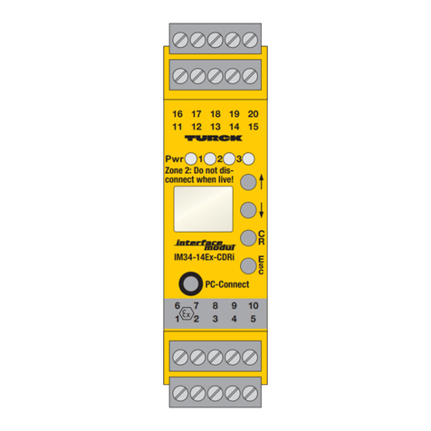
turck IM33-14Ex-CDRi User manual

turck

turck IM33-14Ex-CDRi User manual

turck IMC-AIA-11Ex-I/24VDC User manual

turck

turck IMC-AIA-11Ex-I/24VDC User manual

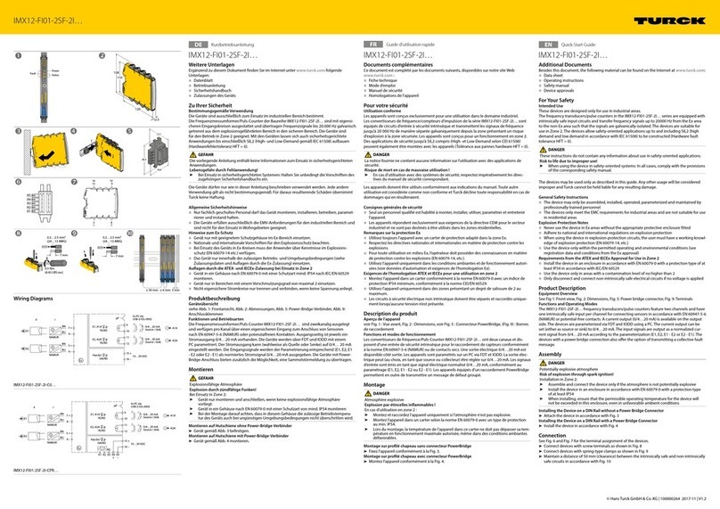
turck IMX12-FI01-2SF-2I Series User manual

turck

turck IMX12-FI01-2SF-2I Series User manual

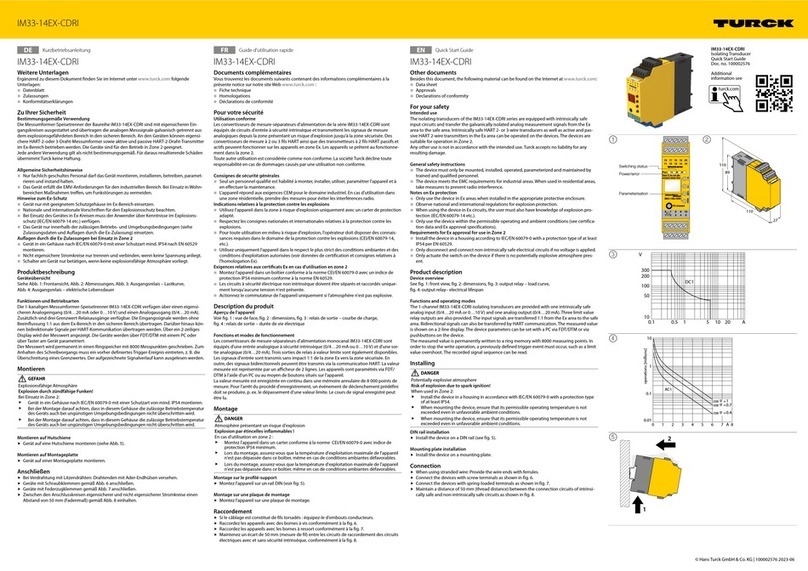
turck IM33-14Ex-CDRi User manual

turck

turck IM33-14Ex-CDRi User manual

turck HART IM33-11Ex-Hi User manual

turck

turck HART IM33-11Ex-Hi User manual

turck EZ-track Q21D Series User manual

turck

turck EZ-track Q21D Series User manual

turck HART IM33-11-Hi/24VDC Series User manual

turck

turck HART IM33-11-Hi/24VDC Series User manual

turck IME-AIA-11Ex-Hi/24VDC User manual

turck

turck IME-AIA-11Ex-Hi/24VDC User manual

turck IM12-TI02-2TCURTDR-2I Series User manual

turck

turck IM12-TI02-2TCURTDR-2I Series User manual

turck IMX12-SG Series User manual

turck

turck IMX12-SG Series User manual

turck LTX-R10 Series User manual

turck

turck LTX-R10 Series User manual

turck IM34-14Ex-CDRi User manual

turck

turck IM34-14Ex-CDRi User manual

turck HART IM33-11-Hi/24VDC Series User manual

turck

turck HART IM33-11-Hi/24VDC Series User manual

turck IM33-22EX-HI/24VDC User manual

turck

turck IM33-22EX-HI/24VDC User manual

turck EZ-track Q21 Series LDT User manual

turck

turck EZ-track Q21 Series LDT User manual

turck IM33-FSD-Ex/L User manual

turck

turck IM33-FSD-Ex/L User manual

turck IMX12-FI01-1SF-1I1R Series User manual

turck

turck IMX12-FI01-1SF-1I1R Series User manual

turck interface modul IMC-AIA-11Ex-i/24VDC User manual

turck

turck interface modul IMC-AIA-11Ex-i/24VDC User manual

turck IM12-TI01 Series User manual

turck

turck IM12-TI01 Series User manual

turck IM12-FI01-1SF-1R User guide

turck

turck IM12-FI01-1SF-1R User guide

turck HART IM33-11-Hi/24VDC Series User guide

turck

turck HART IM33-11-Hi/24VDC Series User guide

Popular Transducer manuals by other brands

WIKA CPT6010 operating instructions

WIKA

WIKA CPT6010 operating instructions

Setra Systems DPT267 Series operating instructions

Setra Systems

Setra Systems DPT267 Series operating instructions

Airmar P66 Owners and installation manual

Airmar

Airmar P66 Owners and installation manual

Nexus NX2 installation manual

Nexus

Nexus NX2 installation manual

controlair 500-AA Installation, operation and maintenance instructions

controlair

controlair 500-AA Installation, operation and maintenance instructions

novotechnik RFC-4800 CAN user manual

novotechnik

novotechnik RFC-4800 CAN user manual

Kron WA user guide

Kron

Kron WA user guide

Lumel P300 user manual

Lumel

Lumel P300 user manual

Agilent Technologies IMG-300 instruction manual

Agilent Technologies

Agilent Technologies IMG-300 instruction manual

Endress+Hauser Cerabar T PMC131 operating instructions

Endress+Hauser

Endress+Hauser Cerabar T PMC131 operating instructions

Philips Avalon CTS M2720A Service guide

Philips

Philips Avalon CTS M2720A Service guide

Bamo MAXIMAT SHR CS instruction manual

Bamo

Bamo MAXIMAT SHR CS instruction manual

Humminbird ICE Flasher Series installation guide

Humminbird

Humminbird ICE Flasher Series installation guide

Airmar CM599LH Owner's guide and installation instructions

Airmar

Airmar CM599LH Owner's guide and installation instructions

UIS WDI-220A installation guide

UIS

UIS WDI-220A installation guide

MKS Baratron 722A manual

MKS

MKS Baratron 722A manual

S+S Regeltechnik THERMASGARD MWTM Series Operating Instructions, Mounting & Installation

S+S Regeltechnik

S+S Regeltechnik THERMASGARD MWTM Series Operating Instructions, Mounting & Installation

Milltronics ST-100 SERIES instruction manual

Milltronics

Milltronics ST-100 SERIES instruction manual

manuals.online logo
manuals.online logoBrands
  • About & Mission
  • Contact us
  • Privacy Policy
  • Terms and Conditions

Copyright 2025 Manuals.Online. All Rights Reserved.