manuals.online logo
Brands
  1. Home
  2. •
  3. Brands
  4. •
  5. Tyco Electronics
  6. •
  7. Power Tools
  8. •
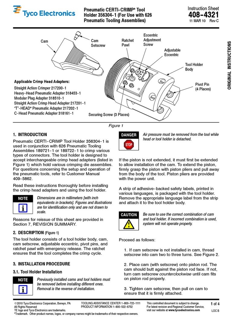
  9. Tyco Electronics AMP PRO-CRIMPER III User manual

Tyco Electronics AMP PRO-CRIMPER III User manual

Instruction Sheet
PRO-CRIMPER III Han Tool an Die 790163 408-8738
E
2004 Tyco Electronics Corporation, Harrisburg, PA
All International Rights Reserved
A P and Tyco are trademarks. *Trademark
Other products, logos, and company names used are the property of their respective owners. LOC B
1
of 4
TOOLING ASSISTANCE CENTER 1-800-722-1111
FAX/PRODUCT INFO 1-800-522-6752
For Regional Customer Service, visit our website at
www.tycoelectronics.com
This controlled document is subject to change.
For latest revision, call the FAX/PRODUCT INFO number.
01 SEP 04 Rev O
for EMT Mo ular Plug Connectors
PROPER USE GUIDELINES
CumulativeTraumaDisorderscanresultfromtheprolongeduseofmanuallypoweredhandtools.Handtoolsareintendedforoccasionaluseandlowvolume
applications. A wide selection of powered application equipment for extended-use, production operations is available.
Stationary Jaw
Front of Tool
Die Assembly
oving Jaw
Ratchet
Adjustment
Wheel
oving Handle
Stationary
Handle
PRO-CRI PER III
Hand Tool Frame
Pivot
Pin
Back of
Tool
The PRO-CRI PER III Hand
Tool is a Commercial" grade tool
and is designed primarily for field
installation, repair, maintenance
work, or prototyping in industrial,
specification, but may not comply with
other feature parameters of the
specification. Tyco Electgronics offers a
variety of tools to satisfy your
performance requirements. For
additional information, contact the
Tooling Assistance Center at
1-800-722-1111.
commercial, or institutional
applications. Product crimped
with this tool will meet the
crimp height requirement for
hand tools in the appropriate
114 application
PRO-CRIMPER II TOOLING CONNECTOR CONDUCTOR CABLE
Hand Tool
and Die Assy Die
Assy Hand Tool
Frame
E T
odular
Plug AWG Insulation
Diameter
(mm)
Strip
Length
(mm)
Outer
Diameter
(mm)
790163-1 790163-2
354940 2
336330-1
336330-2
26 24
080 100
35 / 5
5.0-6.0
790163-3 790163-4
354940
-
2
336439-1
26
-
24
0
.
80
-
1
.
00
35
+
/
-
5
790163-5 790163-6 336462-1 6.0-7.0
Figure 1
1. INTRODUCTION
PRO–CRIMPER III Hand Tool Assembly consists of
the Hand Tool Frame 354940–2, and the appropriate
die assembly, as listed in the table in Figure 1. The
die assembly consists of an insulation and connector
shield stuffer, a housing support, housing guides, die
retaining pins, and mounting hardware.
Dimensions in this instruction sheet are in
millimeters. Figures and illustrations are for
identification, only, and are not drawn to scale.
2. DESCRIPTION
(Figure 1 and Figure 2)
This tool features a tool frame, a stationary jaw and
handle, a moving jaw, a moving handle, and an
adjustable ratchet that ensures full and complete
crimping of product. The tool frame holds a die
assembly with insulation and connector shield and
contact stuffer.
NOTE
408-8738
PRO-CRIMPER III Hand Tools and Die Assemblies for the EMT Modular Plu
Rev
O2
of 4
Figure 2
Nut
Housing Guide
Wi e Stuffe
Holding Sc ew
Wi e
Stuffe
Insulation
Shield
Stuffe
Tool F ame
Die Retaining
Pin(s)
Die Retaining Sc ew(s)
Housing Guide
Housing Suppo t
Chambe
The die assembly consists of an insulation shield
stuffer and connector shield stuffer, as well as a
housing support, housing guides, die retaining pins,
and die retaining screws. The die retaining pins and
screws secure the die set in the tool frame. Attached
to the outside of the frame are the housing guides. A
nut is used on the lower die retaining screw to secure
the housing guides in place.
3. DIE SET INSTALLATION AND REMOVAL
(Figu e 2)
1. Close the tool handles until the ratchet releases.
Then allow the handles to open fully. Remove both
die retaining screws from the tool jaws if they are
present.
2. Place the insulation–connector shield/wire
stuffer assembly as shown in Figure 2. Insert the
short die retaining pins and short die retaining
screw through the tool frame and tighten the
screw.
3. Place the housing support in the moving jaw of
the tool frame as shown in Figure 2. Mount the
right hand housing guide using the long die
retaining pins and secure with the long die
retaining screw. Mount the left hand housing guide
and tighten the nut.
4. To disassemble, close the tool handles until the
ratchet releases, remove the nut, screws, housing
guides, retaining pins, housing support, and
insulation–connector shield/wire stuffer assembly.
4. CRIMPING PROCEDURE
This too is provided with a crimp-adjustment
feature, initia y, the crimp height shou d be
verified as in Figure 3. Refer to Section 5, CRIMP
HEIGHT INSPECTION to verify the crimp height
before using the too to crimp the desire
connector.
Before proceeding, ensure that the cable and plug are
compatible, and that the cable polarity is correctly
maintained for your specification application.
Refer to Application Specification 114–22008 for
cable preparation, conductor arrangement, insertion
and crimping and proceed as follows.
1. Hold the tool so the back is facing you. Squeeze
the tool handles together and allow them to open
fully.
2. Insert the plug assembly (plug, cable, and
shield) fully into the die cavity until the plug
bottoms in the die cavity.
Before insta ing the p ug into the die, make sure
that the connector shie d is fu y bottomed onto
the body. In some cab es with
Shielded Twisted
Pairs
, this check is especia y important.
3. Squeeze the tool handles until the product is
crimped and the ratchet releases.
4. Remove the terminated modular plug cable
assembly.
5. Check the crimp height as described in Section
5, CRIMP HEIGHT INSPECTION. Adjust as
necessary as described in Paragraph 6.1, Crimp
Height Adjustment.
NOTE
CAUTION
408-8738
PRO-CRIMPER III Han Tools an Die Assemblies for the EMT Mo ular Plug
3
o 4Rev
O
Figure 3
Modular Plug
Connector Housing
Support
Cable Shield
Wire Stu er
Holding Screw
Contact Stu er
6.02 +/-0.13
0.80 Max
Housing
Contact
Wire
Holder
Insulation
Shield
Stu er
5. CRIMP HEIGHT INSPECTION
Figure 3 shows a cut–away of a typical terminated
plug and the required location of the conductors. A
visual inspection through the plastic housing of the
plug should reveal whether the conductors are within
the acceptable range.
Inspect the connector for proper crimp height using
an indicator with needle–point probes. Refer to
Figure 3 for the appropriate crimp height
measurement. If necessary, adjust the crimp height
as described in Paragraph 6.1, Crimp Height
Adjustment.
6. ADJUSTMENTS
6.1. Crimp Height A justment
(Figure 4)
1. Remove the lockscrew from the ratchet
adjustment wheel.
2. With a screwdriver, adjust the ratchet wheel
from the opposite side of the tool.
3. While facing the ratchet adjustment wheel,
adjust the crimp.
a. If a tighter crimp is required, rotate the
adjustment wheel counterclockwise to a
higher–numbered setting.
b. If a looser crimp is required, rotate the
adjustment wheel clockwise to a
lower–numbered setting.
4. Replace the lockscrew.
5. Make a sample crimp and measure the crimp
height. If the dimension is acceptable, secure the
lockscrew. If the dimension is unacceptable,
continue to adjust the ratchet, and again measure
a sample crimp.
If correct crimp height cannot be obtained, the tool
and/or dies must be replaced. Refer to Section 8,
PARTS REPLACEMENT.
6.2. Wire Stuffer A justment
If the wire stuffer is not assembled onto the insulation
stuffer (or there are doubts about a correct
adjustment of these two parts), proceed as described
below.
Figure 4
Screwdriver
Lock-Screw
(Typ)
Ratchet
Adjustment
Wheel
408-8738
PRO-CRIMPER III Hand Tools and Die Assemblies for the EMT Modular Plug
Rev
O4
of 4
1. Assemble the wire stuffer onto the insulation
stuffer with the 4–40 UNC X .621 In. socket head
cap screw included with the die set.
Do NOT tighten the screw. Loosen it if it is
already tight.
2. Open the tool jaws and insert a plug assembly
(without the cable) into the jaw cavity.
3. Squeeze the tool handles and keep them
closed.
4. Insert a key into the wire stuffer holding screw
and tighten it.
5. Open the tool and remove the crimped plug. At
this point the wire stuffer is held in its proper
position.
7. MAINTENANCE AND INSPECTION
7.1. Daily Maintenan e
Tyco Electronics recommends that operators of the
tool be made aware of, and are responsible for, the
following steps of daily maintenance.
1. Remove dust, moisture, and any other
contaminants from the tool with a clean, soft brush,
or a clean, soft, lint–free cloth. Do NOT use hard or
abrasive objects that could damage the tool.
2. Make certain that the retaining pins are in place
and that they are secured with retaining rings.
3. All pins, pivot points, and bearing surfaces
should be protected with a thin coat of any good
grade SAE 20 motor oil.
Do
no
t oil excessively.
4. When the tool is not in use, keep the handles
closed to prevent objects from becoming lodged in
the crimping jaws.
5. Store the tool in a clean, dry area.
7.2. Periodi Inspe tion
Regular inspection of the tool should be performed by
quality control personnel. A record of the scheduled
inspections should remain with the tool or be supplied
to supervisory personnel responsible for the tool.
Inspection frequency should be based on:
S
amount of use;
S
working conditions;
S
operator training and skill; and
S
established company standards.
7.3. Visual Inspe tion
The crimping dies should be inspected on a regular
basis to ensure they have not become worn or
damaged. Inspect the crimp sections for flattened,
chipped, worn, or broken areas. If damage or
abnormal wear is evident, the tool must be replaced.
Refer to Section 8, PARTS REPLACEMENT.
1. Remove all lubrication and accumulated film by
immersing the tool (handles partially closed) in a
suitable commercial degreaser that will NOT affect
paint or plastic material.
2. Make certain that the retaining pins are in place
and that they are secured with retaining rings.
3. Close the tool handles until the ratchet releases,
and then allow the handles to open freely. If they
do not open quickly and fully, the spring is
defective and must be replaced.
4. Inspect the tool frame for wear or damage,
paying particular attention to the tool jaws and the
pivot points. If damage is evident, replace it. If
damage is not evident, lubricate the pivot point and
return the tool to service.
5. Check the dies occasionally to make sure the
dies are not broken or chipped. If damage is
evident, replace them.
8. CUSTOMER REPLACEABLE PARTS
Customer–replaceable parts are shown in Figure 1.
Available separately, PRO–CRIMPER III Repair Kit
679221–1 includes a replacement nut and a variety of
pins, rings, screws, and springs. If the dies are
damaged or worn excessively, they must be replaced.
Order the repair kit and replaceable parts through
your Tyco Electronics Representative, or call
1–800–526–5142, or send a facsimile of your
purchase order to 1–717–986–7605, or write to:
CUSTOMER SERVICE (38–35)
TYCO ELECTRONICS CORPORATION
P.O. BOX 3608
HARRISBURG, PA 17105–3608
9. REVISION SUMMARY
New release per EC 0990–0929–04
NOTE
NOTE

Other Tyco Electronics Power Tools manuals

Tyco Electronics DYNA-CRIMP 69066 User manual

Tyco Electronics

Tyco Electronics DYNA-CRIMP 69066 User manual

Tyco Electronics SDE- SA User manual

Tyco Electronics

Tyco Electronics SDE- SA User manual

Tyco Electronics 9-1579004-7 User manual

Tyco Electronics

Tyco Electronics 9-1579004-7 User manual

Tyco Electronics CERTI-LOK AMP DUAC User manual

Tyco Electronics

Tyco Electronics CERTI-LOK AMP DUAC User manual

Tyco Electronics Raychem Interconnect AA-400 Mark IV User manual

Tyco Electronics

Tyco Electronics Raychem Interconnect AA-400 Mark IV User manual

Tyco Electronics Pro-Crimper III User manual

Tyco Electronics

Tyco Electronics Pro-Crimper III User manual

Tyco Electronics 1-1579002-2 User manual

Tyco Electronics

Tyco Electronics 1-1579002-2 User manual

Tyco Electronics PRO-CRIMPER III User manual

Tyco Electronics

Tyco Electronics PRO-CRIMPER III User manual

Tyco Electronics 231652 Series User manual

Tyco Electronics

Tyco Electronics 231652 Series User manual

Tyco Electronics CRIMPAC User manual

Tyco Electronics

Tyco Electronics CRIMPAC User manual

Tyco Electronics PEW 12 User manual

Tyco Electronics

Tyco Electronics PEW 12 User manual

Tyco Electronics 0-0654174-2 User manual

Tyco Electronics

Tyco Electronics 0-0654174-2 User manual

Tyco Electronics 1-528013-1 Reference guide

Tyco Electronics

Tyco Electronics 1-528013-1 Reference guide

Tyco Electronics GET Series User manual

Tyco Electronics

Tyco Electronics GET Series User manual

Tyco Electronics 2063956-1 User manual

Tyco Electronics

Tyco Electronics 2063956-1 User manual

Tyco Electronics AMP-O-LECTRIC 694134-7 Reference guide

Tyco Electronics

Tyco Electronics AMP-O-LECTRIC 694134-7 Reference guide

Tyco Electronics PRO-CRIMPER III User manual

Tyco Electronics

Tyco Electronics PRO-CRIMPER III User manual

Tyco Electronics PRO-CRIMPER III User manual

Tyco Electronics

Tyco Electronics PRO-CRIMPER III User manual

Tyco Electronics 91904 Series User manual

Tyco Electronics

Tyco Electronics 91904 Series User manual

Tyco Electronics 91391-1 User manual

Tyco Electronics

Tyco Electronics 91391-1 User manual

Tyco Electronics PRO-CRIMPER III User manual

Tyco Electronics

Tyco Electronics PRO-CRIMPER III User manual

Tyco Electronics ERGOCRIMP 539 753-2 User manual

Tyco Electronics

Tyco Electronics ERGOCRIMP 539 753-2 User manual

Tyco Electronics Duoplug MK II User manual

Tyco Electronics

Tyco Electronics Duoplug MK II User manual

Tyco Electronics AMP PRO-CRIMPER III User manual

Tyco Electronics

Tyco Electronics AMP PRO-CRIMPER III User manual

Popular Power Tools manuals by other brands

HIKOKI RH 18DA Handing instructions

HIKOKI

HIKOKI RH 18DA Handing instructions

Shop fox Shop Fox W1674 owner's manual

Shop fox

Shop fox Shop Fox W1674 owner's manual

TOOLCRAFT 2480786 operating instructions

TOOLCRAFT

TOOLCRAFT 2480786 operating instructions

Beta BETA 599DGT-AN 10 Operation manual and instructions

Beta

Beta BETA 599DGT-AN 10 Operation manual and instructions

Tohnichi CTA2-G instruction manual

Tohnichi

Tohnichi CTA2-G instruction manual

Milwaukee M18 BMT Original instructions

Milwaukee

Milwaukee M18 BMT Original instructions

Mannesmann 92575 instruction manual

Mannesmann

Mannesmann 92575 instruction manual

DTS DTS170 quick start

DTS

DTS DTS170 quick start

Porter-Cable PCC650 instruction manual

Porter-Cable

Porter-Cable PCC650 instruction manual

Cutech 40180H user manual

Cutech

Cutech 40180H user manual

Hitachi N 5008AB instruction manual

Hitachi

Hitachi N 5008AB instruction manual

Steel City 40300 owner's manual

Steel City

Steel City 40300 owner's manual

Sealey AK629 manual

Sealey

Sealey AK629 manual

SCOPREGA GE BP instructions

SCOPREGA

SCOPREGA GE BP instructions

Simpson PT-27 Operator's manual

Simpson

Simpson PT-27 Operator's manual

FXA FXAJD5242K instruction manual

FXA

FXA FXAJD5242K instruction manual

joke ENESKAsonic operating instructions

joke

joke ENESKAsonic operating instructions

King Industrial KC-10HJC instruction manual

King Industrial

King Industrial KC-10HJC instruction manual

manuals.online logo
manuals.online logoBrands
  • About & Mission
  • Contact us
  • Privacy Policy
  • Terms and Conditions

Copyright 2025 Manuals.Online. All Rights Reserved.