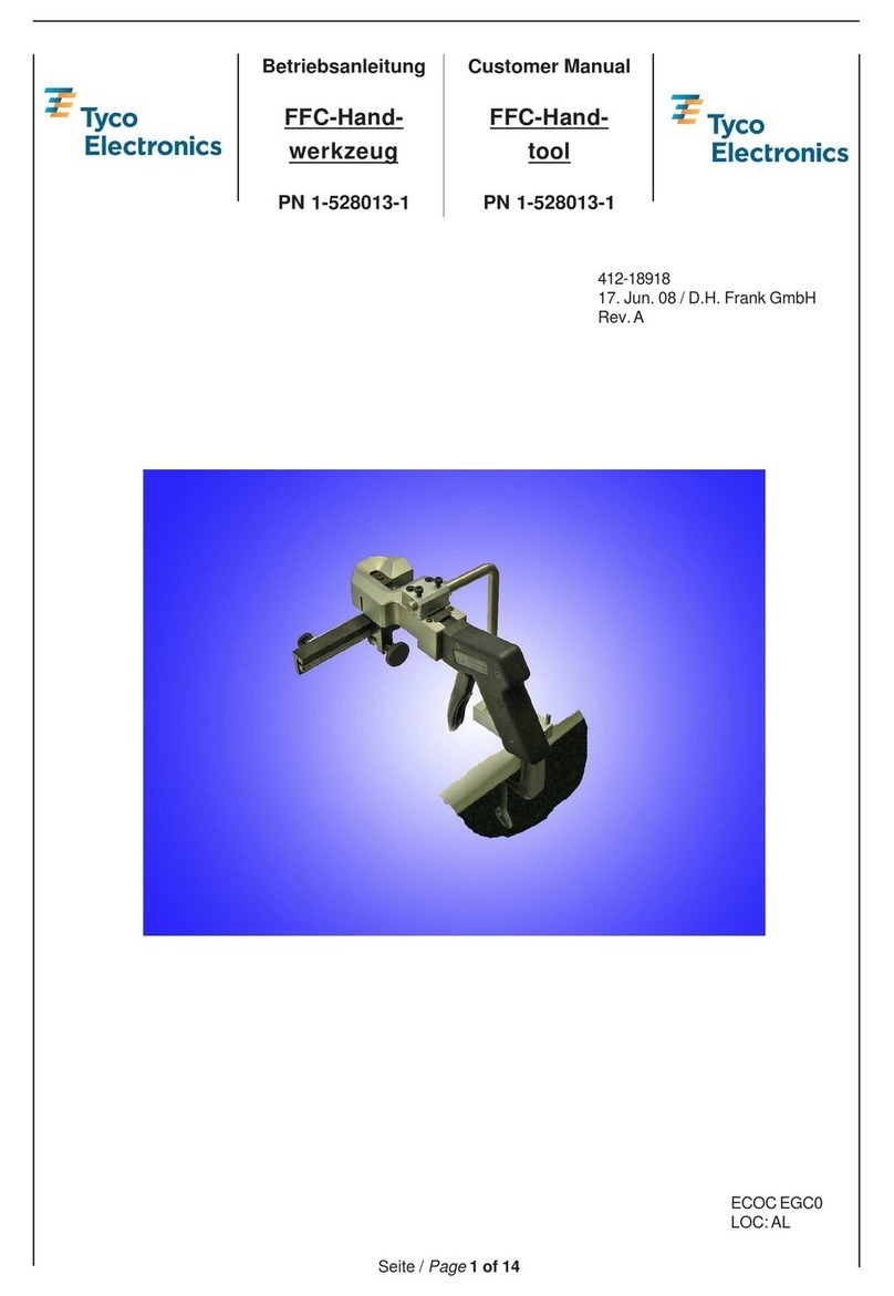
PRESSEMANUELLEHYDRAULIQUE
HAND-OPERATEDHYDRAULICTOOL
SIMABLOC 80+
SIMABLOC 80+SIMABLOC 80+
SIMABLOC 80+
Reference 789082-1 – code: 018895
Manueld’entretien
Technicalhandbook
1390289-1indice A
Modified in 03/02
3/9
Tyco Electronics SIMEL S.A – Route de Saulon. 21220 GEVREY CHANBERTIN – France . Tel: +33(0) 3 80 58 32 00 – Fax: +33(0) 3 8034 1015
2.
2.2.
2. INSTRUCTIONS
INSTRUCTIONSINSTRUCTIONS
INSTRUCTIONS
D’UTILISATION
D’UTILISATIOND’UTILISATION
D’UTILISATION 2.
2.2.
2. OPERATING
OPERATINGOPERATING
OPERATING
INSTRUCTIONS
INSTRUCTIONSINSTRUCTIONS
INSTRUCTIONS
- NE JAMAIS METTRE EN
PRESSION LES MATRICES SANS
CONNECTEURENTRE
- NEVER DO A CYCLE WITH DIES
WITHOUT CONNECTOR INSIDE THE
DIES
- Mise en place et retrait des
- Mise en place et retrait des- Mise en place et retrait des
- Mise en place et retrait des
matrices
matricesmatrices
matrices(figure1)
- Tourner le bouton moleté de
l’axe de verrouillage pour le
dégager.
- Orienter les parties pour
mettre en vis à vis les
empreintesàutiliser
- Introduire la matrice dans les
rainuresdeguidagedelachape
- Repousser l’axe totalement et
tourner le bouton moleté,
jusqu’enbutéepour le bloquer
- Si l’axe n’est pas enfoncé
totalement, le verrouillage avec
le bouton moleté ne se fera pas
et l’axe sera repoussé par le
ressort
- Procéder à l’inverse pour retirer
lesmatrices
-Dies insertingand removing
-Dies insertingand removing-Dies insertingand removing
-Dies insertingand removing
(picture 1)
- Turn the knob of the locking axis
counter-clock wise in order to unlock
it.
- Ensure that the crimp surfaces are
properlyoriented.
- Place the dies in the clevis, using the
guideindentations.
- Push the locking axis back in
completely and turn the knob
clockwiseuntilitstops.
- If the locking axis is not correctly in
place either, the locking knob will not
turnor the lockingaxis will be pushed
outby the spring.
-Toremove the dies, unlocktheaxis
- Mettre le connecteur à sertir
dans le tête de sertissage entre
les deux matrices (figure2)
- Put the connector between the two
parts ofthe dies(picture 2)
SERTISSAGE
SERTISSAGESERTISSAGE
SERTISSAGE :
::
: (figure3)
- Actionner le bras mobile. Le
piston se déplace en avance
rapide jusqu’à la saisie du
connecteur puis lentement pour
lesertissage.
- Continuer d’actionner le bras
mobile jusqu’au “clic”audible.
CRIMPING:
CRIMPING:CRIMPING:
CRIMPING:(picture3)
- Work the movable arm. The piston
moves forward quickly until is made
with the connector and then slowly
forcrimping.
-Pumpup totheaudible “clic”.
Les 2 parties de la matrice
Les 2 parties de la matriceLes 2 parties de la matrice
Les 2 parties de la matrice
doivent toujours être en
doivent toujours être endoivent toujours être en
doivent toujours être en
contacten fin de sertissage
contacten fin de sertissagecontacten fin de sertissage
contacten fin de sertissage
Always check that the two part
Always check that the two partAlways check that the two part
Always check that the two part
of the dies are in contact at the
of the dies are in contact at theof the dies are in contact at the
of the dies are in contact at the
endof the crimp
endof the crimpendof the crimp
endof the crimp
RETOUR PISTON :
RETOUR PISTON :RETOUR PISTON :
RETOUR PISTON : (figure 4)
- Écarter légèrement le bras
mobile, le tourner sur lui même
jusqu’en butée et le refermer à
fond
RELEASE::
RELEASE::RELEASE::
RELEASE:: (picture 4)
- Separate the movable arm from the
fixed arm, turn it until it can go no
further, then bring both arms back
together
- Effectuer les autres sertissages
delamême façon - Perform other crimps in thesame way
Retraitdelamatrice
RetraitdelamatriceRetraitdelamatrice
Retraitde la matrice: (figure5)
- Tourner le bouton moleté de
l’axe de verrouillage, il sera
repoussé par le ressort.
- Retirer la matrice
Removing the dies:
Removing the dies:Removing the dies:
Removing the dies: (picture 5)
-
--
- Unlock the locking axis with the knob,
this axis will be pushed out by the
spring
-
--
-Removethe dies
