408-10182
PEW 12 Han Tool Assembly 2031243-1
Rev
B2
of 4 Tyco Electro ics Corporatio
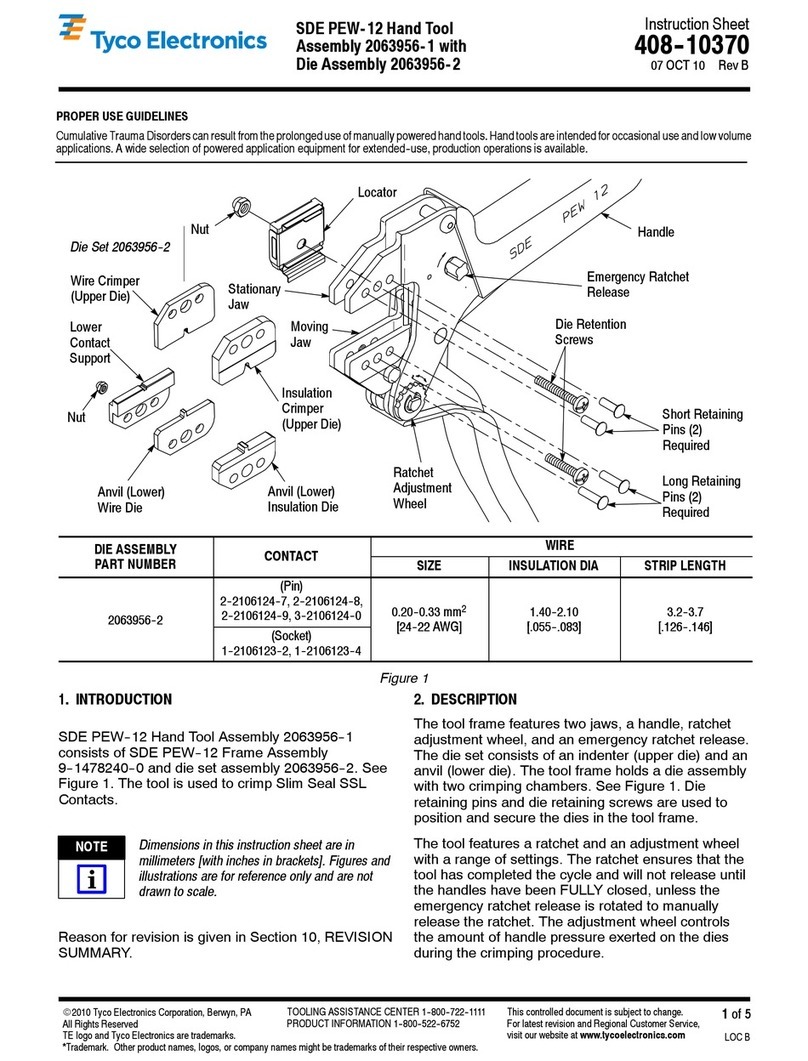
Figure 2
Chamfer
I sulatio
Crimper
Tool Frame
Die Retai i g
Pi s
Die Retai i g
Screws
Chamfer
I sulatio
A vil
Wire A vil
Wire
Crimper
Locator
Subassembly
Locki g Nut
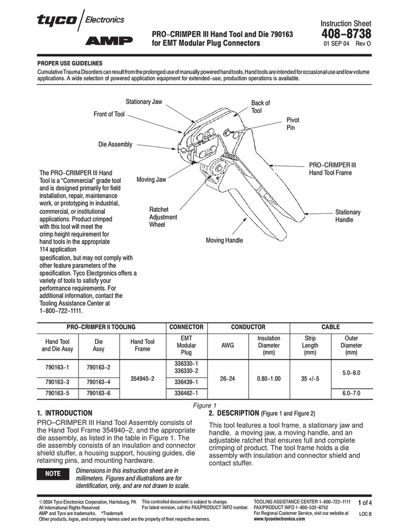
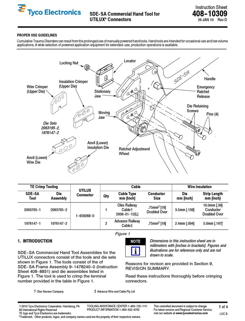
2. DESCRIPTION
(Figures 1 a d 2)
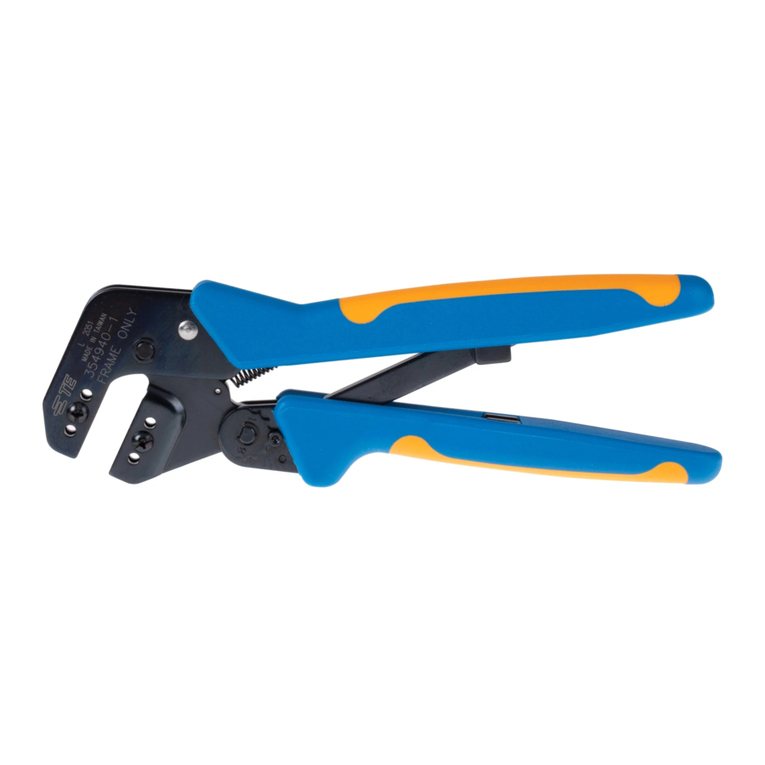
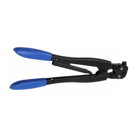
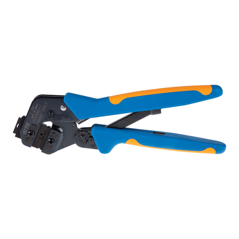
The tool features a tool frame with a stationary jaw
and handle, a moving jaw, a moving handle, and an
adjustable ratchet that ensures full contact crimping.
The tool frame holds a die assembly with two
crimping sections.
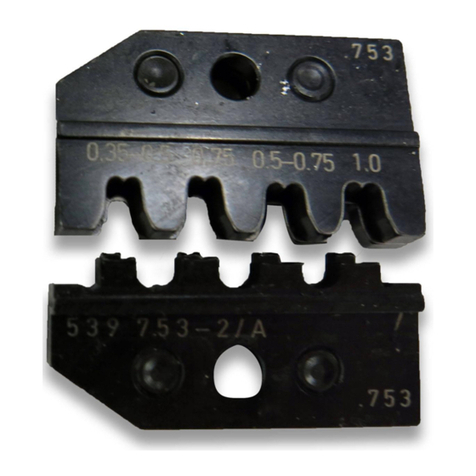
The die assembly features a wire anvil, an insulation
anvil, a wire crimper, and an insulation crimper.
Die retaining pins and die retaining screws are used
to position and secure the dies in the tool frame.
3. INSTALLATION AND REMOVAL OF
DIE SET
(Figure 2)
1. Open the tool handles and remove the two die
retaining screws from the tool jaws.
2. Place the wire anvil and insulation anvil so that
their chamfered sides and their marked surfaces
face outward, when mounted in the moving jaw of
the tool frame.
3. Insert the two die retaining pins.
4. Insert a die retaining screw through the jaw and
through both anvil dies, and tighten the screw just
enough to hold the dies in place. Do
not
tighten the
screw completely at this time.
5. Place the wire crimper and insulation crimper so
that their chamfered sides and their marked
surfaces face outward, when mounted in the
stationary jaw of the tool frame.
6. Insert the two die retaining pins.
7. Insert a die retaining screw through the jaw and
through both crimper dies, and tighten the screw
just enough to hold the dies in place. Do
not
tighten the screw completely at this time.
8. Carefully close the tool handles, making sure
that the anvils and crimpers align properly.
Continue closing the tool handles until the ratchet
in the tool frame has engaged sufficiently to hold
the anvils and crimpers in place, then tighten both
die retaining screws.
9. To disassemble, close the tool handles until the
ratchet releases, remove the two die retaining
screws and the four die retaining pins, and slide
the anvils and crimpers out of the tool jaws.
4. CRIMPING PROCEDURE
Th s tool s prov ded w th a cr mp adjustment
feature. Int ally, the cr mp he ght should be
ver f ed as spec f ed n F gure 4. Refer to
Sect on 5, CRIMP HEIGHT INSPECTION, and
Sect on 6, CRIMP HEIGHT ADJUSTMENT, to
ver fy cr mp he ght before us ng the tool to cr mp
des red term nals and w re s zes.
Refer to the table in Figure 1 and select wire of the
specified size and insulation diameter. Strip the wire
to the length indicated in Figure 1, taking care not to
nick or cut wire strands. Select an applicable terminal
and identify the appropriate crimp section according
to the wire size markings on the tool. Refer to
Figure 3 and proceed as follows:
1. Hold the tool so that the back (wire side) is
facing you. Squeeze tool handles together and
allow them to open fully.
NOTE
i
