Tzora Easy Travel Elite User manual

Service Manual

Easy Travel – Service Manual Rev. 0401 2

Easy Travel – Service Manual Rev. 0401 3
Table of contents:
1. System components and details 4
2. Annual maintenance service 5
3. Spare parts replacement 6
4. Programming 46
5. Fault finding 48
6. Electrical wiring 49
7. Charger 50
8. Spare parts 51
9. List of Tool Types 54
NOTE: Design details may change without notice

Easy Travel – Service Manual Rev. 0401 4
1. SYSTEM COMPONENTS AND DETAILS
1.1 EasyTravel parts – (Figure 1)
1. Battery pack (detachable)
2. Front column (detachable)
3. Column lock/release triggers
4. Controller cover
5. Charging socket (Fig. 1A)
6. Front drive wheels
7. Foot platform
8. Seat shell
9. Seat cushions
10. Serial # up to and including: fold-
ing seat latch
11. Rear wheel
12. Folded frame lock pin
13. Platform bottom lock pin
14. Utility basket (holding capacity
9kg)
15. Charger and connecting cables
(Fig. 1B).
16. Control Panel
17. Freewheel switch
1.2 Control Panel – Figure 2
1. Switch
2. Hand control lever (right and left)
3. Speed adjusting knob
4. Indicator light (LED)
5. From serial # 0307077and on-
wards or starting with 11B: Battery
Level Indicator
6. Hand-grips
BELL: If the user requires an audible warn-
ing device, a standard bicycle bell can be
attached to the handlebar.

Easy Travel – Service Manual Rev. 0401 5
2. SERVICE
For reasons of safety and the prevention of accidents caused by wear which is not detected in time, the
EasyTravel should be tested and serviced once a year. All safety-related components of the EasyTravel
should be checked and serviced, safety and functional tests should be performed. It is important to detect
initial wear in time and to use exclusively original spares, or such parts that were authorized by the manu-
facturer.
Test the following maintenance items:
The components of the EasyTravel
frame for overload and initial cracks.
Wear of tires on wheels.
All screws and attachments for safe
securing, cable connections for
wear, and the mechanisms of the
EasyTravel for correct functioning.
The proper functioning of the elec-
tronic system and brakes.
For serial # up to and including
0304599: the collector brushes of
the electric motor (3-A) for wear.
Wear limit is approx. 7 mm.
Figure 3

Easy Travel – Service Manual Rev. 0401 6
3. SPARE PARTS REPLACEMENT
3.1 Control Panel Assembly
Kit number E0-00-1-040 (for serial # up to
and including 0307076)
Kit Number E0-00-1-202 (for serial #
0307077 and onwards)
Kit Number E0-00-1-701 (for serial # with
13 digits, starting with 11B (Taiwan))
Tools:
Phillips #2 Screwdriver
For serial # and onwards, see next page.
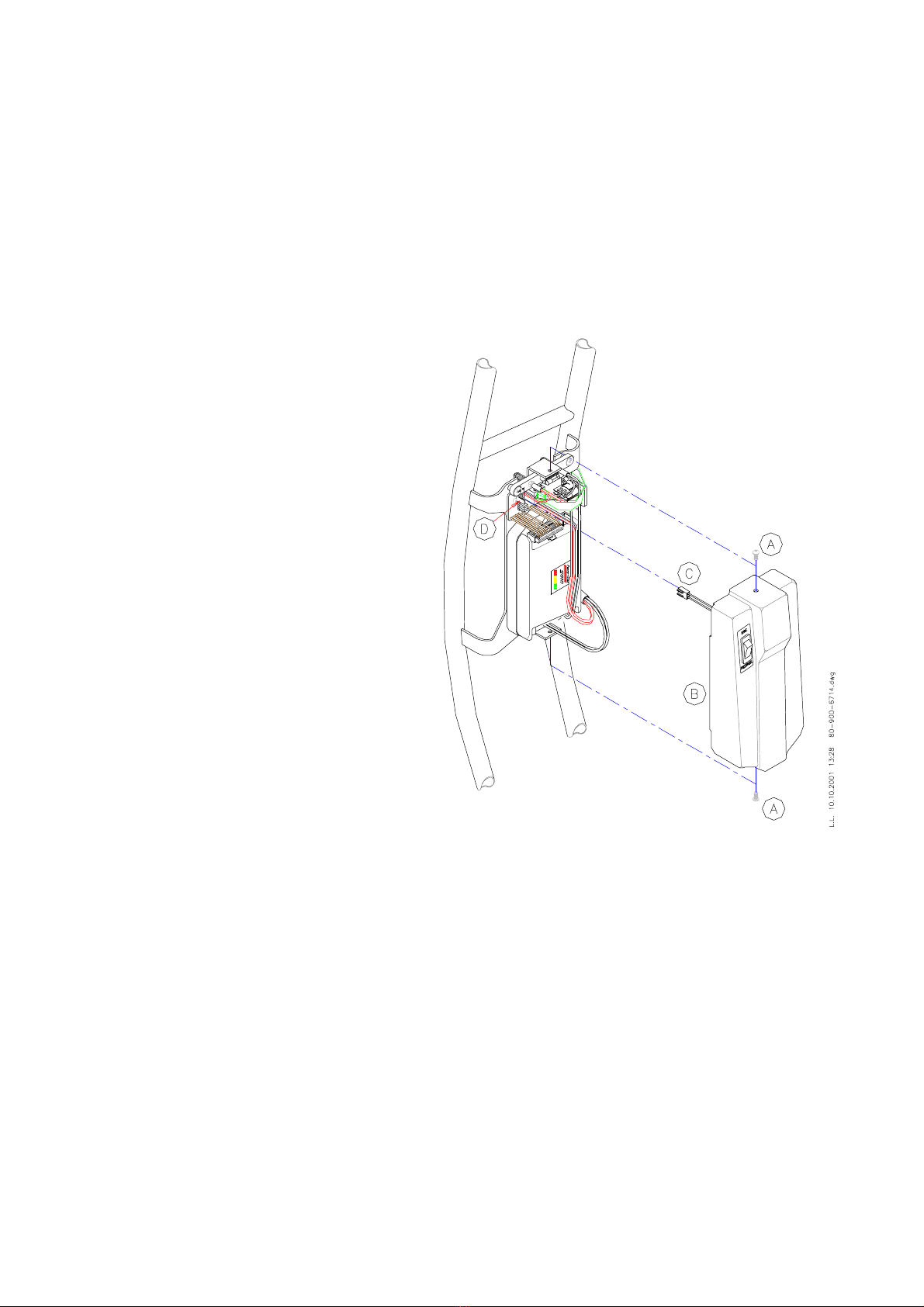
1. Push Handgrips (4-A) outwards
2. Open Screws (4-B) and remove Control
Panel Cover (4-C)
3. Disconnect the Control Cable (4-D)
4. Open Screws (4-E) and remove Control
Panel (4-F)
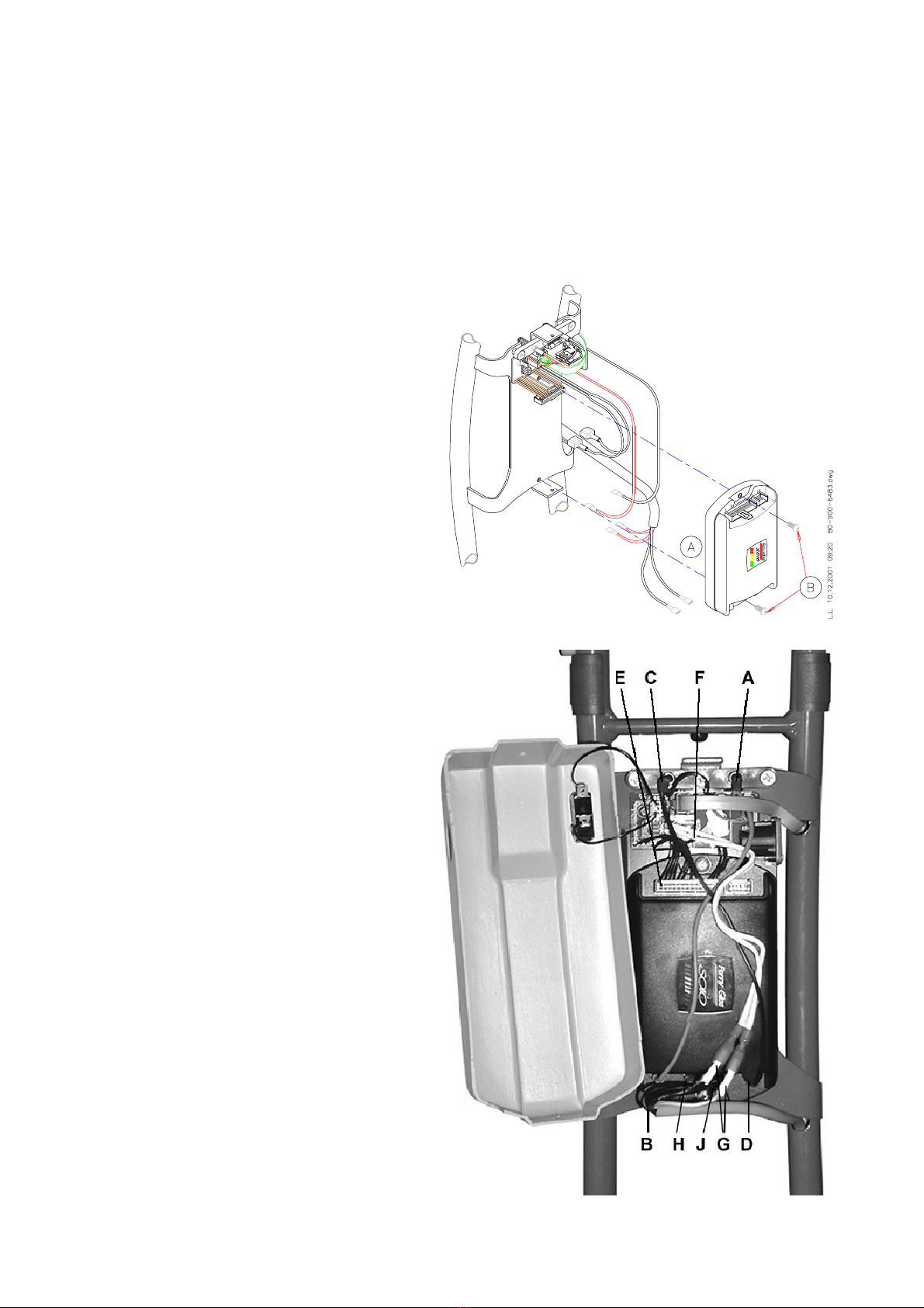
5. Open Screws (4-N) and remove Panel
Bottom Cover (4-P)
6. Place new Bottom Cover (4-P) and
secure it with Screws (4-N)
7. Secure new Control Panel (4-F) with
Screws (4-E)
8. Connect the Control Cable (4-D) to Con-
trol Panel (4-F)
9. Secure Control Panel Cover (4-C) with
Screws (4-B)
10. Push Handgrips (4-A) back over the
Cover
11. Check all Control Panel functions: indi-
cation, drive, brake and speed control
Figure 4

Easy Travel – Service Manual Rev. 0401 7
Kit Number E0-00-1-202
Kit Number E0-00-1-701
Tools:
Phillips #2 Screwdriver
1. Open Screws (5-A) and remove top and
bottom Control Panel Cover (5-B, C)
2. Disconnect the Control Cable (5-D)
3. Open Screws (5-E) and remove Control
Panel (5-F)
4. Secure new Control Panel (5-F) with
Screws (5-E)
5. Connect the Control Cable (5-D) to Con-
trol Panel (5-F)
6. Secure top and bottom Control Panel
Cover (5-B, C) with Screws (5-A)
7. Check all Control Panel functions: indi-
cation, drive, brake and speed control
Figure 5

Easy Travel – Service Manual Rev. 0401 8
3.2 Handgrip pair
Kit number E0-00-1-070
Tools:
Silicone spray
Phillips #2 Screwdriver
1. Remove Control Panel Assembly, see
instructions 3.1
2. For serial # up to and including
0307076: open Screws (6-A) and
remove Control Panel Bottom Cover (6-
B)
3. Remove the Handgrips, (7-A)
4. Spray Handlebars (7-B) of the Column
Frame and inside of the new Handgrips
lightly with Silicone Spray and push
them onto the Column Frame
5. Reassemble Control Panel Bottom
Cover and Control Panel Assembly
6. Push the Handgrips back over both
Covers
NOTE: Check that Handgrips do not slide off
of Covers easily – this can cause a safety
hazard if control lever gets caught under
Handgrip edge. Remove excess silicon if
needed.
Figure 7
Figure 6

Easy Travel – Service Manual Rev. 0401 9
3.3 Controller Cover ET1B
Kit Number E0-00-1-034
Kit Number E0-00-1-705 (for serial # start-
ing with 11B)
Tools:
Phillips #2 Screwdriver
1. Remove Screws (8-A) at the top and
bottom of the Controller Cover (8-B) and
remove Cover
2. Disconnect Connector (8-C) from Inter-
face Circuit Board (8-D)
3. Check that the solder tabs of the Free-
wheel Switch on new Cover are bent
apart
4. Insert Connector of new Cover (8-C) to
Interface Circuit Board
5. Secure the Cover on the Column
NOTE: Ensure that the Power Cable is
routed under the Controller (see Figure
10) and that it will not be pinched when
closing and securing the Cover
6. Check drive, brake and freewheel op-
eration
Figure 8

Easy Travel – Service Manual Rev. 0401 10
3.4 Solo Controller ET1B
Kit Number E0-00-1-032
Kit Number E0-00-1-704 (for serial # start-
ing with 11B)
Tools:
Short Phillips #2 Screwdriver
Pliers
1. Remove Controller Cover, see instruc-
tion 3.3
2. Detach wiring from Controller (9-A)
3. Remove Controller (9-A) by unscrewing
Screws (9-B)
4. Secure new Controller to Column Frame
5. Attach Wires to Controller (Fig. 9a): from
Battery Contacts Assembly, the red wire
(A) to “B+” tab (B), the black (C) to “B-“
tab (D); from Interface Circuit Board in-
sert 11-pin connector into top socket P2
(E); the two white wires (F) to the white
capped cables (G) from Power Cable;
from Power Cable the #1 wire to “M+”
tab (H), the #2 to “M-“ tab (J)
6. Secure Controller Cover to Column
Frame
7. Check drive, brake and freewheel op-
eration
Figure 9a
Figure 9

Easy Travel – Service Manual Rev. 0401 11
Kit Number E0-00-1-704 (for serial # start-
ing with 11B)
Tools:
Short Phillips #2 Screwdriver
Pliers
1. Remove Controller Cover, see 3.3
2. Open Screws (10-A), remove Controller
Top and plastic protection sheet
3. Detach wiring from Controller
4. Open Screws (10-B) on reverse side of
Steering Column and remove Controller
5. Secure new Controller to Column Frame
6. Attach Wires to Controller (Fig. 10a):
a. Control Cable (C);
b. from Contacts and Charging Socket
Assembly:
i. the brown wire to connector (B),
ii. the white wire to connector (F),
iii. the red wire to “B+” tab, the black
to “B-“ tab (D);
iv. the two red capped wires (coming
from connector (F)) to the white
and yellow/green cables (G) from
Power Cable;
c. from Power Cable the #1/red wire to
“M+” tab, #2/black wire to “M-“ tab (E)
7. Place plastic protection sheet and se-
cure Controller Top Cover with Screws
(10-A)
8. Secure Controller Cover, see 3.3
9. Check drive, brake and freewheel op-
eration
Figure 10a
Figure 10

Easy Travel – Service Manual Rev. 0401 12
3.5 Battery Contacts
Kit number E0-00-1-059
Tools:
Phillips #2 Screwdriver
1. Remove Controller Cover, see
instruction 3.3
2. Disconnect wiring to Controller (11-A)
and Interface Circuit Board (11-B)
3. Unscrew Screws (11-C) and remove
Battery Contacts Assembly (11-D)
4. Secure new Battery Contacts Assembly
(11-D) with Screws (11-C)
5. Connect Wiring (11-A) to Controller (red
to “B+” tab, black to “B-“ tab), Connector
(11-B) onto Interface Circuit Board
6. Reassemble Controller Cover, see
instruction 3.3
7. Check drive, brake and freewheel
operation
Figure 11

Easy Travel – Service Manual Rev. 0401 13
3.6 Interface Circuit Board ET1B
Kit number E0-00-1-058
Tools:
Phillips #1 Screwdriver
Phillips #2 Screwdriver
1. Remove Controller Cover, see instruc-
tion 3.3
2. Disconnect Control Cable (12-A), Free-
wheel Cable (12-B), wiring to Controller
(12-C), Contact Pins Assembly (12-D)
and to Power Cable (12-E)
3. Unscrew 3 Screws (12-F) and remove
Interface Circuit Board (12-G)
4. Secure new Interface Circuit Board (12-
G) with Screws (12-F)
5. Connect Control Cable (Fig. 12-A),
Freewheel Cable (12-B), wiring to Con-
troller (12-C), Contact Pins Assembly
(12-D) and Power Cable (12-E)
6. Reassemble Controller Cover
7. Check drive, brake and freewheel op-
eration
Figure 12

Easy Travel – Service Manual Rev. 0401 14
3.7 Contacts and Charging Socket Assembly
Kit number E0-00-1-703 (for serial # start-
ing with 11B)
Tools:
Phillips #1 Screwdriver
Phillips #2 Screwdriver
1. Remove Controller Cover, see instruc-
tion 3.3
2. Open Controller, see instruction 3.4
3. Disconnect wiring to Controller and to
Power Cable, see instruction 3.4
4. Unscrew 3 Screws (12a-A) and two
Screws (12a-B)
5. Remove Contacts and Charging Socket
Assembly (12a-C) and replace
6. Secure new Assembly (12a-C) with
Screws (12a-A, B)
7. Connect wiring to Controller and Power
Cable and close Controller, see instruc-
tion 3.4
8. Reassemble Controller Cover, see in-
struction 3.3
9. Check drive, brake and freewheel op-
eration
Figure 12a

Easy Travel – Service Manual Rev. 0401 15
3.8 Control Cable
Kit number E0-00-1-054
Kit Number E0-00-1-702 (for serial # start-
ing with 11B)
Tools:
Phillips #2 Screwdriver
1. Open Control Panel Cover, see instruc-
tion 3.1
2. Open Controller Cover, see instruction
3.3
3. Disconnect Control Cable from Control
Panel (5-C) and Interface Circuit Board
(12-A)/Controller (10a-C)
4. Remove Control Cable
5. Insert new Control Cable (if needed, re-
move the Paint Protector and replace it
with a new one after the Control Cable is
inserted, see instruction 3.32)
6. Connect Control Cable to Control Panel
and Interface Circuit Board/Controller
7. Reassemble Controller Cover and Con-
trol Panel Cover, see instructions 3.1
and 3.4
8. Check all Control Panel and Controller
functions: drive, brake, speed and indi-
cation

Easy Travel – Service Manual Rev. 0401 16
3.9 Motor End Cover ET1B
Kit Number E0-00-1-083 (for motor types
E0-00-1-036 and E0-00-1-092)
Tools:
Phillips #2 Screwdriver
1. Unscrew Screw (13-A) and remove
Cover (13-B)
2. Note the motor wire routing and main-
tain it in position
NOTE: If force is needed to fit Cover,
check the wire routing and ensure that it
will not be pinched
3. Secure new Cover (13-B) with Screw
(13-A)
Kit Number E0-00-1-096 (for motor type
E0-00-1-094)
Tools:
Phillips #2 Screwdriver
1. Unscrew Screws (14-A) and remove
Cover (14-B)
2. Note the motor wire routing and main-
tain it in position
NOTE: If force is needed to fit Cover,
check the wire routing and ensure that it
will not be pinched
3. Secure new Cover (14-B) with Screws
(14-A)
Figure 13
Figure 14

Easy Travel – Service Manual Rev. 0401 17
3.10 Motor Brushes
Kit Number E0-00-1-037 (for serial # up to
and including 0304599)
Tools:
Phillips #2 Screwdriver
Flat Blade Screwdriver
(For EasyTravel with serial number up to
and including 0212052:
Hot Air Gun (if available)
Soldering Iron and Solder)
Please refer to Figure 13
1. Remove the Motor End Cover, see in-
struction 3.8
2. Remove the plastic Brush Cap (C) and
pull the Brush gently from its housing
3. Remove Power Cable wire
For serial # up to and including
0212052:
Remove heat-shrink insulation and un-
solder the Brush (Fig. 15) being re-
placed
4. Insert the new Brush carefully into its
housing and secure with Brush Cap (C)
NOTE: Ensure that the Brush is fully in-
serted freely and smoothly and that the
spring is not caught in the housing
5. Connect Power Cable wire to contact
tab
For serial # up to and including
0212052:
a. Place new heat-shrink insulation
sleeves over wires and re-solder wiring
to contact tab
NOTE: Ensure good tinning and secure
connection
b. Secure insulation sleeves in place
with hot air gun or soldering iron
6. Note the motor wire routing and main-
tain it in position.
7. Secure Motor Cover, see instruction 3.8
8. Check drive and brake operation
Figure 15

Easy Travel – Service Manual Rev. 0401 18
3.11 Power Cable to Motor ET1B
Kit Number E0-00-1-056 (for serial # up to
and including 0212052)
Kit Number E0-00-1-093 (for serial #
0212053 up to 0304599)
Kit Number E0-00-1-095 (for serial #
0304600 and onwards)
Kit Number E0-00-1-706 (for serial #
starting with 11B)
Tools:
Phillips #2 Screwdriver
Pliers
Cutter
Cable Tie Tensioning Tool
(For serial # up to and including 0212052:
Soldering Iron
Solder
Hot Air Gun)
The wheels MAY be removed to facilitate
easier access for the replacement of parts,
see instruction 3.11
Fig. 16a refers to serial # up to and including
0212052, fig. 16b refers to serial # 0212053
up to 0304599, fig. 16c refers to serial #
0304600 and onwards.
1. Remove the Motor Cover, see instruc-
tion 3.8 (for serial # starting with 11B:
remove heat shrink)
2. Remove Cable Ties (16-A) from Motor
and Securing Clip (16-B) on the under-
side of the Adapter Block
3. Remove Wires from Terminals (16-C)
and Brakes (16-D)
For serial # up to and including
0212052:
Remove heat-shrink insulation and un-
solder the Wires from the Terminals (16-
C) and Brakes (16-D) on the Motor
4. Remove Controller Cover, see instruc-
tion 3.3
5. Detach the Wires from the Controller
(17-A) and Interface Circuit Board (17-B)
6. Carefully pull the Power Cable out of the
Column Frame
Figure 16a
Figure 16b

Easy Travel – Service Manual Rev. 0401 19
7. Thread the new Power Cable from the
Controller-end into the hole in the Col-
umn Frame out of tube and under the
Adapter Block, as depicted in Fig. 16
8. Connect the #1/red insulated Wire end
to positive/red colored Terminal, the
#2/black insulated Wire end to nega-
tive/black Terminal, the #3 and green
Wire to white Wires from electromag-
netic Brake
(For serial # up to and including
0212052:
a. Place new heat-shrink insulation
sleeves over wires and solder the #1
long Wire end to positive/red colored
Terminal, the #2 short Wire end to nega-
tive/black colored Terminal, the #3 and
green wire to white Wires from the elec-
tromagnetic Brake
b. Secure insulation sleeves in place
with hot air gun or soldering iron)
9. Secure the Cable to the Motor with Ca-
ble Ties (16-A) and trim ends (for serial
# starting with 11B: Place new heat
shrink over Motor
10. Secure the cable to the underside of the
Adapter Block with Clip (16-B)
11. Secure the Motor Cover over the end of
the Motor
NOTE: If force is needed to fit Motor
Cover, check the wire routing and en-
sure that it will not be pinched
12. Attach from the Power Cable the black
insulated #1 Wire End to “M+” tab, the
red insulated #2 to “M-“ tab on Controller
and the two white insulated Wire Ends
to the Wires from Interface Circuit Board
13. Secure Controller Cover to the Frame,
ensure that no wires will be pinched or
damaged by the Cover or the Screws
14. Check drive, brake and freewheel func-
tion
Figure 17
Figure 16c

Easy Travel – Service Manual Rev. 0401 20
3.12 Front Wheel Assembly
Kit Number E0-00-1-069
Tools:
Allen Key 6 mm
Loctite Adhesive #242 (1312)
Soft Mallet
1. Remove old Cap (18-A), Screw (18-B),
Disk (18-C) and Wheel (18-D)
2. Thoroughly clean the threaded hole in
the end of the Axle (18-E) of adhesive
residue
3. Slide the Wheel (18-D) onto Axle (18-E)
aligning the groove in the Adapter with
the Roll Pin on the Axle
4. Place Disk (18-C) on Screw (18-B) and
apply Loctite #242 (1312) adhesive to
the screw thread
5. Secure the assembly with Screw (18-C).
6. Fit new Cap (18-A) on the Wheel (18-D)
by gently tapping it with a mallet
Figure 18
Table of contents
Other Tzora Scooter manuals

Tzora
Tzora Elite User manual

Tzora
Tzora Titan User manual

Tzora
Tzora Lexis Light User manual

Tzora
Tzora EasyTravel Classic User manual

Tzora
Tzora EasyTravel Elite ET1E User manual

Tzora
Tzora Titan 3W User manual

Tzora
Tzora EasyTravel Elite User manual

Tzora
Tzora EasyTravel Lite User manual

Tzora
Tzora Titan User manual