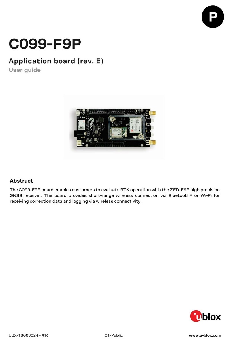
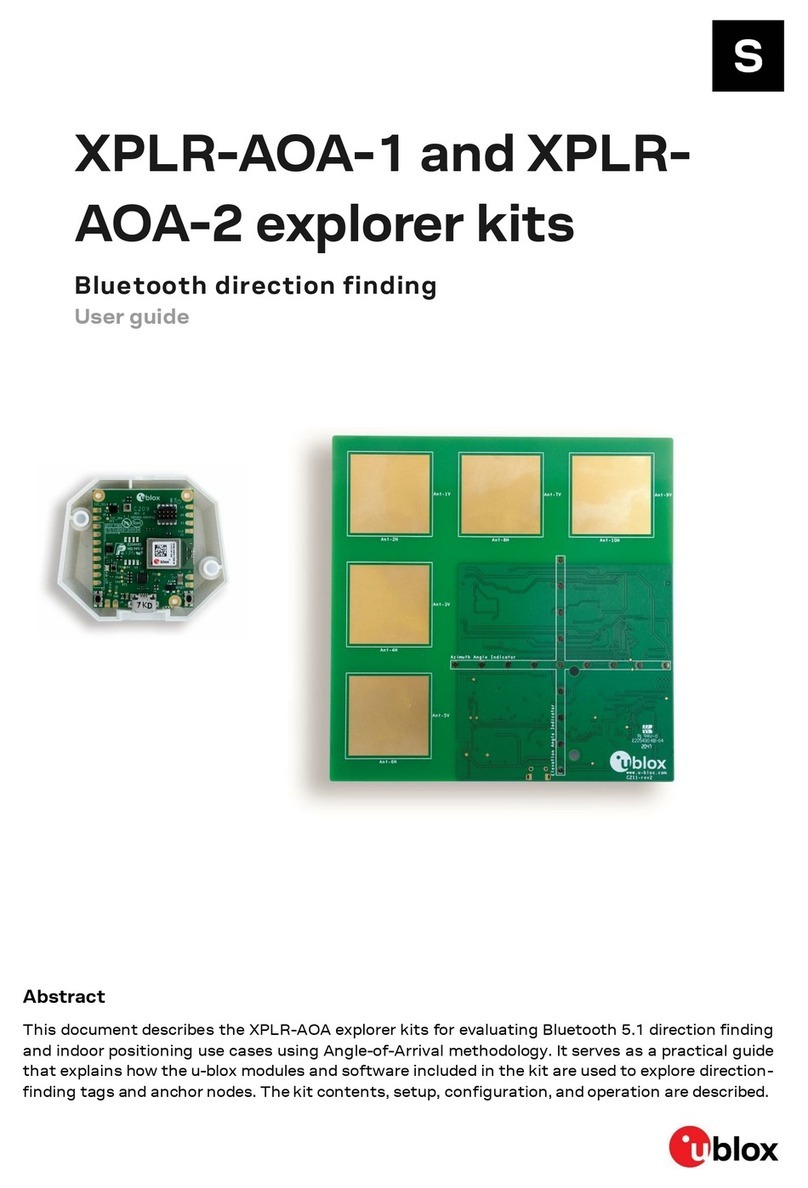
Ublox EVK-NORA-B1 User manual

UBX-20030319 - R06
C1-Public www.u-blox.com
EVK-NORA-B1
Evaluation kit for NORA-B1 series modules
User guide
Abstract
This document describes how to set up the EVK-NORA-B100, EVK-NORA-B106, EVK_NORA-B126
and EVK_NORA_B120 evaluation kits to evaluate the NORA-B1 series modules. It also describes
the different options for debugging and the development capabilities included in the evaluation
board.

EVK-NORA-B1 - User guide
UBX-20030319 - R06 Document information Page 2 of 31
C1-Public
Document information
Title
EVK-NORA-B1
Subtitle
Evaluation kit for NORA-B1 series modules
Document type
User guide
Document number
UBX-20030319
Revision and date
R06
24-Aug-2022
Disclosure restriction
C1-Public
Product status
Corresponding content status
In development /
Prototype
Objective specification
Target values. Revised and supplementary data will be published later.
Engineering sample
Advance information
Data based on early testing. Revised and supplementary data will be published later.
Initial production
Early production information
Data from product verification. Revised and supplementary data may be published later.
Mass production/
End of life
Production information
Document contains the final product specification.
This document applies to the following products:
Product name
Document status
EVK-NORA-B100
Early production information
EVK-NORA-B106
Early production information
EVK-NORA-B120
Advance information
EVK-NORA-B126
Advance information
☞For information about the hardware, software, and status of the available product types, see the
NORA-B1 data sheet [1].
u- -blox or third parties may hold intellectual property rights in the products, names, logos and designs included in this
document. Copying, reproduction, or modification of this document or any part thereof is only permitted with the express
written permission of u-blox. Disclosure to third parties is permitted for clearly public documents only.
The information contained herein is provided “as is”. No warranty of any kind, either express or implied, is made in relation to
the accuracy, reliability, fitness for a particular purpose or content of this document. This document may be revised by u-blox
at any time. For most recent documents, please visit www.u-blox.com.
Copyright © u-blox AG.

EVK-NORA-B1 - User guide
UBX-20030319 - R06 Contents Page 3 of 31
C1-Public
Contents
Document information................................................................................................................................2
Contents ..........................................................................................................................................................3
1Product description ..............................................................................................................................4
1.1 Key features .................................................................................................................................................4
1.2 Items included in kit.................................................................................................................................... 5
1.2.1 EVK-NORA-B100 kit contents ......................................................................................................... 5
1.2.2 EVK-NORA-B106 kit contents ......................................................................................................... 5
1.2.3 EVK-NORA-B120 kit contents ......................................................................................................... 5
1.2.4 EVK-NORA-B126 kit contents .........................................................................................................5
1.3 Development tools ...................................................................................................................................... 5
2Hardware description...........................................................................................................................7
2.1 Power .............................................................................................................................................................7
2.1.1 Low-voltage mode .............................................................................................................................. 7
2.1.2 High-voltage mode (EVK-NORA-B10 only).................................................................................... 8
2.2 Reset..............................................................................................................................................................9
2.3 Buttons..........................................................................................................................................................9
2.4 LEDs.............................................................................................................................................................10
2.5 Serial communication ..............................................................................................................................11
2.6 32.768 kHz low frequency clock.............................................................................................................12
2.7 NFC connector ...........................................................................................................................................13
2.8 Current sensing headers .........................................................................................................................14
2.9 Debug indicators .......................................................................................................................................14
2.10 External SEGGER J-Link™ debug interface ........................................................................................15
2.11 QSPI .............................................................................................................................................................16
2.12 GPIO jumpers .............................................................................................................................................16
2.13 Header pin-out ...........................................................................................................................................17
3Application development................................................................................................................. 21
3.1 Install Visual Studio Code........................................................................................................................21
3.2 Install nRF Connect for Desktop............................................................................................................21
3.2.1 Install nRF Connect SDK .................................................................................................................22
3.2.2 Visual Studio Code............................................................................................................................22
3.2.3 Board support package ...................................................................................................................23
3.2.4 Create a new application .................................................................................................................23
3.3 Test the application..................................................................................................................................27
Appendix ....................................................................................................................................................... 30
AGlossary ................................................................................................................................................. 30
Related documentation ........................................................................................................................... 31
Revision history.......................................................................................................................................... 31
Contact.......................................................................................................................................................... 31

EVK-NORA-B1 - User guide
UBX-20030319 - R06 Product description Page 4 of 31
C1-Public
1Product description
The EVK-NORA-B1 evaluation kit provides stand-alone use of the NORA-B1 series module featuring
the Nordic Semiconductor nRF5340 dual-core RF System on Chip (SoC).
The evaluation kit provides a great starting point for almost any Bluetooth® 5.2 Low Energy (LE),
Thread, or Zigbee project. All features of the NORA-B1 series modules are easily accessed from the
evaluation board. A simple USB connection provides power, programming, and virtual COM ports. Four
user buttons are available, as well as a USB peripheral connector, user LEDs, and a reset button.
48 GPIO (46 for EVK-NORA-B12) signals are available on headers that are compatible with the
Arduino® form factor. This allows easy use of existing Arduino shields. Current sense resistors allow
for measuring current into the module and into the shield.
This guide provides setup instructions for starting development and describes the hardware
functionality of the EVK-NORA-B1 board.
1.1 Key features
•Used for evaluation of NORA-B1 modules
oNORA-B100 or NORA-B101: EVK-NORA-B100
oNORA-B106: EVK-NORA-B106
oNORA-B120 or, NORA-B121: EVK-NORA-B120
oNORA-B126: EVK-NORA-B126
•On-board programming and debug (SEGGER J-Link-OB)
•Able to program external modules
•Virtual COM ports over USB
•48 GPIO (EVK-NORA-B10), 46 GPIO (EVK-NORA-B12)
•Buttons and LEDs for user interaction
•NFC antenna connector
•32.768 kHz Crystal
•CR2032 coin cell battery holder
•USB peripheral connector
•Power input connectors
•Power mode selection switches (EVK-NORA-B10 only)
•PA/LNA support (EVK-NORA-B12 only)
Figure 1: EVK-NORA-B1 evaluation board (top view)

EVK-NORA-B1 - User guide
UBX-20030319 - R06 Product description Page 5 of 31
C1-Public
1.2 Items included in kit
1.2.1 EVK-NORA-B100 kit contents
•EVK-NORA-B10 evaluation board with NORA-B100 module
•Micro-USB cable
•NFC antenna
•2.4 GHz U.FL antenna kit
•10-pin SWD programming cable, 2x5 headers on 1.27 mm centers
☞For evaluation of the NORA-B101 module, select the EVK-NORA-B100 kit. Only the antenna
connection point is different.
1.2.2 EVK-NORA-B106 kit contents
•EVK-NORA-B10 evaluation board with NORA-B106 module
•Micro-USB cable
•NFC antenna
•2.4 GHz antenna integrated onto NORA-B106 module (no external antenna)
•10-pin SWD programming cable, 2x5 headers on 1.27 mm centers
1.2.3 EVK-NORA-B120 kit contents
•EVK-NORA-B12 evaluation board with NORA-B120 module
•Micro-USB cable
•NFC antenna
•2.4 GHz U.FL antenna kit
•10-pin SWD programming cable, 2x5 headers on 1.27 mm centers
☞For evaluation of the NORA-B121 module, select the EVK-NORA-B120 kit. Only the antenna
connection point is different.
1.2.4 EVK-NORA-B126 kit contents
•EVK-NORA-B12 evaluation board with NORA-B126 module
•Micro-USB cable
•NFC antenna
•2.4 GHz antenna integrated onto NORA-B126 module (no external antenna)
•10-pin SWD programming cable, 2x5 headers on 1.27 mm centers
1.3 Development tools
The tools shown in Table 1 aid the development of NORA-B1 series Bluetooth modules.
Tool
Description
Nordic Semiconductor
nRF Connect for Desktop
nRF Connect for Desktop is the primary development tool used with the NORA-B1 series
modules. This tool includes an installation and maintenance utility for the nRF Connect SDK,
Toolchain Manager.
nRF Connect for Desktop is a cross-platform tool that also enables testing and development
with Bluetooth LE. It allows easy setup of connections with other devices and uses these
connections to read and write the external nodes. Available for Windows, macOS, and Linux.
Nordic Semiconductor
Command Line Tools
The nRF Command Line Tools is used for development, programming and debugging of
Nordic Semiconductor’s nRF53 and other nRF series devices.
Microsoft Visual Studio Code
(VS Code)
Visual Studio Code is a lightweight but powerful source code editor which runs on your
desktop and is available for Windows, macOS and Linux.

EVK-NORA-B1 - User guide
UBX-20030319 - R06 Product description Page 6 of 31
C1-Public
Tool
Description
Nordic Semiconductor’s nRF Connect extension pack turns VS Code into a complete IDE for
developing applications for NORA-B1 and other Nordic Semiconductor based u-blox modules.
This includes an interface to the compiler and linker, an RTOS-aware debugger, a seamless
interface to the nRF Connect SDK and a serial terminal among other useful tools. A
DeviceTree viewer is also included. It visualizes the configured hardware and helps you easily
navigate the DeviceTree source. Adding custom boards is made significantly simpler through
the help of the Create New Board wizard.
Nordic Semiconductor
nRF Connect SDK (NCS)
nRF Connect SDK contains several components, including the Zephyr RTOS, MCUboot, and
nrfxlib peripheral libraries for the nRF5340 CPU within the NORA-B1 series modules.
Installation of NCS is managed through nRF Connect for Desktop. Available for 32- and 64-
bit Windows, macOS, and 64-bit Linux platforms.
Nordic Command Line Tools are installed with NCS, including nrfjprog.
Nordic Semiconductor
nRF Connect for Mobile
(optional)
nRF Connect for Mobile is a powerful generic tool that allows you to scan and explore your
Bluetooth LE devices and communicate with them. nRF Connect for Mobile supports several
Bluetooth SIG adopted profiles, as well as the Device Firmware Update profile (DFU) from
Nordic Semiconductor or Eddystone from Google. Available for iOS and Android. Installation
is nRF Connect for Mobile is optional.
Nordic Semiconductor
Mobile Apps (optional)
Additional, optional mobile utilities for application development. Available for iOS and
Android.
SEGGER J-Link Software and
Documentation Pack
J-Link Commander (JLink.exe) is a command line-based utility that can be used for verifying
proper functionality of J-Link as well as for simple analysis of the target system. It supports
some simple commands, such as memory dump, halt, step, and go, to verify the target
connection. Available for Windows, macOS, and Linux platforms.
Table 1: Development tools

EVK-NORA-B1 - User guide
UBX-20030319 - R06 Hardware description Page 7 of 31
C1-Public
2Hardware description
Design files in Altium, PDF, and Gerber formats for EVK-NORA-B1 PCBs may be requested from your
local u-blox support team.
2.1 Power
EVK-NORA-B1 has six possible power sources, as described below:
Number
Source
Description
Minimum
Typical
Max
1
V5DEBUG
Power to debug interface USB port
3.8 VDC
5.0 VDC
5.5 VDC
2
VMODUSB
Power to NORA-B1 USB interface
3.8 VDC
5.0 VDC
5.5 VDC
3
Li-Po header
J26 battery connector
3.8 VDC
5.5 VDC
4
Arduino VIN
J27 or J9
3.8VDC
5.5 VDC
5
CR2032 battery
BAT1 coin cell holder
1.7 VDC
3.0 VDC
3.6 VDC
6
External connector
J17
1.7 VDC
3.3 VDC
3.6 VDC
Table 2: EVK power sources
Power sources 1 through 4 are connected through Maxim MAX40203AUK+T ideal protection diodes
1
to create VBUS_H, allowing selection of the highest input voltage.
VDD (3.3 VDC) is generated from VBUS_H. VDD, and power sources 5 and 6, are connected through
ideal protection diodes to create VBUS from the highest voltage of these three sources.
☞The debug interface and associated level shifters are only enabled when V5DEBUG is present.
Otherwise, the debug interface is held in reset and level shifters disabled to conserve system
power.
⚠Normally open, solder jumpers are provided to allow by-passing any of the protection diodes. Care
should be taken not to damage the supplies when the protection is disabled by soldering across
any of these jumpers.
For details regarding measuring current, see Current sensing headers.
2.1.1 Low-voltage mode
☞The HV mode switch, SW1, in the schematic is labeled “Module power” on the silk screen.
With the power switch in the ON position, and the HV mode switch in the LV (low-voltage) position,
NORA-B1 is powered by VMOD. The following power signals are active:
•VDD, sourced by 3.3V LDO = debug interface power and reference voltage. Level shifters are used
to allow independent NORA-B1 I/O voltage settings
•VSYS, sourced by VBUS = EVK system power
•VSHLD, sourced by VSYS = power source for shields connected through the Arduino header, J27
and J9
•VMOD, sourced by VSYS = NORA-B1 VDD module power input and I/O reference voltage
•VMODH, sourced by VMOD = NORA-B1 VDDH module power input (bypass NORA-B1 HV LDO)
⚠Only if the power protection circuits are left intact can USB be safely connected at the same time
as the coin cell or external power. This allows programming of the module while leaving other power
sources connected.
1
Maxim MAX40203AUK+T ideal protection diodes provide maximum forward voltage drop of 28 mV at 100 mA and prevent
reverse current flow to other connected supplies.

EVK-NORA-B1 - User guide
UBX-20030319 - R06 Hardware description Page 8 of 31
C1-Public
2.1.2 High-voltage mode (EVK-NORA-B10 only)
☞The HV mode switch, SW1, in the schematic is labeled “Module power” on the silk screen.
With the power switch in the ON position, and the HV mode switch in the HV (high-voltage) position,
NORA-B10 is powered by VMODH. The following power signals are active:
•VDD, sourced by 3.3V LDO = debug interface power and reference voltage. Level shifters are used
to allow independent NORA-B1 I/O voltage settings
•VMOD, sourced by NORA-B1 VDD = 1.8 VDC to 3.3 VDC supply output, configured by application
software, and I/O voltage reference for NORA-B10.
•VSYS, sourced by VMOD = EVK system power
•VSHLD, sourced by VSYS = power source for shields connected through the Arduino header, J27
and J9
•VHV, sourced by VBUS_H = power from sources 1 through 4.
•VMODH, sourced by VHV = NORA-B10 VDDH module power input
☞EVK-NORA-B12 does not support high voltage mode. The HV mode switch is not present.
Figure 2: EVK schematic –power supply

EVK-NORA-B1 - User guide
UBX-20030319 - R06 Hardware description Page 9 of 31
C1-Public
2.2 Reset
The EVK-NORA-B1 provides a configurable hardware reset to the NORA-B1 module. The Reset button
can be configured to connect to an input on the interface IC or to directly connect to nRESET signal in
the module.
The reset button is connected to the debug interface chip by default. Pressing reset while the
interface IC is powered causes a momentary reset signal on the nMOD_RESET output of the interface
IC, which converted to the VSYS I/O voltage for the module. If the reset button is held down during the
EVK power on, it causes the interface IC to enter its bootloader mode, which allows programming of
the SEGGER J-Link interface.
Solder jumpers JRST1 and JRST2 allow the reset button to bypass the interface circuit and connect
directly to the nRESET signal on the module.
Figure 3: EVK schematic –reset
Signal name
Description
IMCU_BOOT
Input to interface chip. During normal operation, drive low to reset the NORA-B1. Drive low during
power-up to enter bootloader mode on the interface chip.
nRESET
NORA-B1 reset signal at the NORA-B1 I/O voltage.
nMOD_RESET
NORA-B1 reset signal at the interface chip I/O voltage.
nSHLD_RESET
I/O header shield reset signal (J27, pin 3)
Table 3: EVK reset signals
2.3 Buttons
The evaluation board has four user buttons that are active low and connect to ground when pressed.
Table 4 associates the button number and corresponding components.
Button
Switch
GPIO
Jumper
Protection diode
1
SW4
P0.23
J24
D7
2
SW5
P0.24
J21
D8
3
SW7
P0.08
J22
D11
4
SW8
P0.09
J23
D12
Table 4: User button components
The internal pull-up resistor of each NORA-B1 GPIO pin must be enabled for proper operation.
☞Example programs in the SDK enable the pull-up resistors by default.
The buttons and ESD protection can be completely removed from the circuit by breaking the
associated jumper.

EVK-NORA-B1 - User guide
UBX-20030319 - R06 Hardware description Page 10 of 31
C1-Public
Figure 4: Schematic –user buttons
2.4 LEDs
User LEDs are provided on the evaluation board –two red and two green. An RGB LED is also included
and this can be enabled by changing the position of JLED1.
LEDs are powered by VIO and are active low. The GPIO should be enabled for high drive when sinking
current for the LEDs. The LEDs can be completely removed from the circuit by breaking the
associated jumper.
LED
RGB LED
GPIO
Jumper
Comments
1 Red
Red
P0.28
J4
Change JLED1 for RGB
2 Red
Blue
P0.29
J5
Change JLED1 for RGB
3 Green
Green
P0.30
J7
Change JLED1 for RGB
4 Green
P0.31
J8
Table 5: LED components
Figure 5: Schematic –user LEDs

EVK-NORA-B1 - User guide
UBX-20030319 - R06 Hardware description Page 11 of 31
C1-Public
2.5 Serial communication
The evaluation board allows for easy serial communication with the NORA-B1 module and a connected
computer. The J-Link debug interface IC provides three virtual COM port (VCP) devices:
•The first (VCOM0) is used to obtain debug output and communicate with the network core.
•The second (VCOM1) is not normally used, although it is available through test points on the EVK.
•The third (VCOM2) is used to obtain debug output information and communicate with the
application core.
VCOM Port functions connected to the NORA-B1 module can be disabled through SW2 to allow use
of the GPIO pin for an application function.
Table 6 describes the function and test points for each module pin.
NORA-B1 pin name
NORA-B1 function
Test point / SW2 enable
Interface IC function
P1.01
Network core TXD
SW2 Position 2
RXD VCOM0
P1.00
Network core RXD
SW2 Position 2
TXD VCOM0
P0.11
Network core RTS
SW2 Position 1
CTS VCOM0
P0.10
Network core CTS
SW2 Position 1
RTS VCOM0
N/A
N/A
J6 Pin 22
RXD VCOM1
N/A
N/A
J6 Pin 20
TXD VCOM1
N/A
N/A
J6 Pin 19
CTS VCOM1
N/A
N/A
J6 Pin 21
RTS VCOM1
P0.20
Application core TXD
SW2 Position 3
RXD VCOM2
P0.22
Application core RXD
SW2 Position 3
TXD VCOM2
P0.19
Application core RTS
SW2 Position 4
CTS VCOM2
P0.21
Application core CTS
SW2 Position 4
RTS VCOM2
Table 6: Virtual COM port connections
☞COM port assignments match the Nordic Semiconductor nRF53DK, v1.0.0 [6].

EVK-NORA-B1 - User guide
UBX-20030319 - R06 Hardware description Page 12 of 31
C1-Public
Figure 6: UART level shifters and disable switches
☞Figure 6 reflects Rev D and Rev E hardware versions.
☞For Rev C or earlier hardware versions, applications need to map the following VCOM0 handshake
signals:
oVCOM0_RTS = P0.12
oVCOM0_CTS = P0.10
oVCOM0_TxD = P1.00 (no change)
oVCOM0_RxD = P1.01 (no change)
2.6 32.768 kHz low frequency clock
The low frequency (LF) clock of the NORA-B1 module can have one of four sources:
•Internal ultra-low power RC oscillator –for low-precision timing where low power is the main
requirement
•Internal calibrated RC oscillator –for applications with no strict real-time requirements
•Internal synthesized clock –derived from the 32 MHz clock
•External crystal oscillator –offers the most accurate and lowest power LF clock
The evaluation board has a 32.768 kHz crystal connected to the NORA-B1 module to allow use of the
external crystal oscillator option. Loading capacitors for the oscillator circuit are internal to the nRF53
within the module. Values of 6 pF, 7 pF, and 11 pF can be enabled through register XOSC32KI.INTCAP.

EVK-NORA-B1 - User guide
UBX-20030319 - R06 Hardware description Page 13 of 31
C1-Public
If an internal LF clock source is used, the crystal can be removed from the circuit by opening jumpers
J16 and J19. Soldering across the normally open position connects XL1 and XL2 to the EVK headers.
Figure 7: Schematic –32 kHz crystal
2.7 NFC connector
Connection to an external NFC antenna is provided through a Molex flat-flex connector, part number
051281–0594. Capacitors C48 and C49 provide tuning of the NFC antenna for resonance at
13.56 MHz.
☞The values of C48 and C49 are tuned for use with the supplied NFC antenna. These values might
need to be changed if a different antenna is used. See also the nRF5340 product specification [4].
Figure 8: NFC connector
By default, the NORA-B1 module pins P0.02 and P0.03 are configured for NFC use. These pins can
also be used for digital GPIO functions by modifying the population of R15, R16, R22, and R23 and the
value of the NFCPINS UICR register.
Mode
Populate:
R15
R16
R22
R23
NFCPINS UICR register
NFC (default)
X
X
0xFFFFFFFF (enable protection, use as NFC)
GPIO2,3
X
X
0xFFFFFFFE (disable protection, use as GPIO)
Table 7: P0.02 and P0.03 pin configuration
2
P0.02 and P0.03 have a pad capacitance of approximately TBD pF higher than other GPIO pins.
3
When used as GPIO, P0.02 and P0.03 will exhibit approximately TBD µA leakage when driven to different states.

EVK-NORA-B1 - User guide
UBX-20030319 - R06 Hardware description Page 14 of 31
C1-Public
2.8 Current sensing headers
The evaluation board provides three current sensing headers:
•J14 allows for power consumption measurement of the NORA-B1 module.
•J25 allows for power consumption measurement of the high-voltage input.
•J18 allows for power consumption measurement of the shields connected to the Arduino-style
headers (VSHLD power only).
Each 3-pin 2.54 mm pitch header has two pins connected across a 1 Ωcurrent-sense resistor
powering the module or the shield, and the third pin to ground. To measure current consumption, use
a multimeter or other precision voltage measurement device to measure voltage drop across pins 2
and 3. Current can also be measured directly by opening JRMOD, JRHV, or JRSHD to remove the
current-sense resistor from the circuit. Use an ammeter in series with the two voltage pins.
⚠Pin 1 of J14, J18, and J25 is connected to GND.
Any current sense resistor can be bypassed by soldering the respective jumper: JMOD, JSHD, or JHV.
The default hardware configuration does not require any modification of the current sense headers
for the EVK-NORA-B1 to perform properly.
☞Only current flowing through VMOD into the module is measured; current sunk through GPIO pins
is not measured.
Figure 9: Current sensing header layout
☞EVK-NORA-B12 does not have a high-voltage mode. JHV and JRHV are not present.
2.9 Debug indicators
Three LEDs indicate activity on the associated SWD interface, as shown in Table 8.
LED
Active SWD interface
LED5
On-board NORA-B1 Module
LED6
Shield connected to J9 –accommodates the Nordic Semiconductor Power Profiler Kit (PPK)
LED7
nRF5-based target device connected to J10.
See also External SEGGER J-Link™ debug interface.
Table 8: Debug indicators

EVK-NORA-B1 - User guide
UBX-20030319 - R06 Hardware description Page 15 of 31
C1-Public
2.10 External SEGGER J-Link™ debug interface
External target hardware can be connected to J10 for firmware programming and debug. The
SEGGER debug interface is implemented, as shown in Figure 10.
J3 is implemented with a 2x5, 10-pin header on 1.27 mm centers.
Figure 10: External J-Link debug interface
To enable the external J-Link connection, ensure the following are implemented on the target
hardware:
•EXT_VTG is used by the debug interface as an input to sense power applied to the external circuit.
Only voltages of 3.0 V to 3.3 V are supported. Target hardware operating voltages outside of this
range require the use of an external SEGGER J-Link Debug Probe. Connect EXT_VTG to the
NORA-B1 series power supply (VDD) on the target hardware.
•Connect GND to GND on the target hardware.
•Connect EXT_SWDIO to SWDIO and EXT_SWCLK to SWDCLK on the target NORA-B1 module.
•(Optional) Connect EXT_SWO and/or nEXT_RESET on the target NORA-B1 module.
•Connect external power to the target hardware, and then connect the EVK-NORA-B1 to USB.
☞At this point, the debug interface interacts with the target hardware instead of the on-board
NORA-B1 module. LED7 illuminates to indicate activity at the Debug Out connector.
☞Only Nordic Semiconductor nRF5 devices are supported, including u-blox ANNA-B1, BMD-3,
NINA-B1, NINA-B3, NINA-B4, and NORA-B1 series modules.
☞EVK-NORA-B10 Rev C hardware cannot use the Debug Out connector to program another EVK-
NORA-B10 Rev C EVK through its Debug In port. However, the Debug Out port can be used to
program any other supported target hardware. Other programmers, like the J-Link Base, can be
used to program EVK-NORA-B10 Rev C hardware through its Debug In port. EVK-NORA-B10 Rev
D / Rev E and EVK-NORA-B12 hardware is not restricted.

EVK-NORA-B1 - User guide
UBX-20030319 - R06 Hardware description Page 16 of 31
C1-Public
2.11 QSPI
A 64 Mbit Quad SPI (MX25R6435F) flash is available on the EVK-NORA-B1. This memory can be used
for execute-in-place (XIP) directly from the flash as well as from general data storage.
Figure 11: Quad SPI flash
2.12 GPIO jumpers
Several solder bridge jumpers on the board are available to configure the GPIO functions. Most solder
jumpers are used to remove on-board components from the GPIO nets in the module and
consequently eliminate interference with external circuitry added on the I/O headers.
All GPIOs are directly connected to the I/O Headers by default, except P0.00 and P0.01 (32 kHz
crystal), P0.02 and P0.03 (NFC antenna), and P0.13 –P0.18 (QSPI). These are disconnected from the
I/O headers as they would otherwise interfere with the default functions. The GPIO jumpers and
associated functions are shown on the bottom of the EVK-NORA-B1 PCB.
Figure 12: Legend for GPIO solder bridge jumpers

EVK-NORA-B1 - User guide
UBX-20030319 - R06 Hardware description Page 17 of 31
C1-Public
2.13 Header pin-out
Figure 13 shows the 2.54 mm pitch headers exposing the IO signals in the NORA-B1 module.
Figure 13: EVK-NORA-B1 I/O pin-out
☞EVK-NORA-B12 uses P1.08 as TX_EN and P1.09 as RX_EN FEM control signals. They are available
as test points near the NORA-B12 module on the PCB and N/C on J2.
⚠The I/O pins of the EVK-NORA-B1 are not 5 V tolerant. Arduino Uno® style shields must be
configured to use +3.3 V DC (VSHLD) as the I/O voltage reference.

EVK-NORA-B1 - User guide
UBX-20030319 - R06 Hardware description Page 18 of 31
C1-Public
Table 9 –Table 11 describe the pin assignments of each header.
Pin
Pin name
nRF5340
Function
1
P1.03
P1.03
GPIO/TWI
2
P1.02
P1.02
GPIO/TWI
3
P0.27
P0.27
GPIO/AIN6
4
GND
–
Ground
5
P1.15
P1.15
GPIO
6
P1.14
P1.14
GPIO
7
P1.13
P1.13
GPIO
8
P1.12
P1.12
GPIO
9
P1.11
P1.11
GPIO
10
P1.10
P1.10
GPIO
Table 9: Header J1
Pin
Pin name
nRF5340
Function
1 on EVK-NORA-B10
1 on EVK-NORA-B12
P1.09
N/C
P1.09
N/C
GPIO
N/C
2 on EVK-NORA-B10
2 on EVK-NORA-B12
P1.08
N/C
P1.08
N/C
GPIO
N/C
3
P1.07
P1.07
GPIO
4
P1.06
P1.06
GPIO
5
P1.05
P1.05
GPIO
6
P1.04
P1.04
GPIO
7
P1.01
P1.01
GPIO
8
P1.00
P1.00
GPIO
Table 10: Header J2
☞EVK-NORA-B12 uses P1.08 as TX_EN and P1.09 as RX_EN FEM control signals. These signals are
N/C on J2.
Pin
Pin name
nRF5340
Function
1
P0.10
P0.10
GPIO/TRACEDATA1/MISO
2
P0.09
P0.09
GPIO/TRACEDATA2/MOSI
3
P0.08
P0.08
GPIO/TRACEDATA3/SCK
4
P0.07
P0.07
GPIO/AIN3
5
P0.03
P0.03
OPEN/GPIO
6
P0.02
P0.02
OPEN/GPIO
7
P0.01
P0.01
OPEN/GPIO
8
P0.00
P0.00
OPEN/GPIO
Table 11: Header J3

EVK-NORA-B1 - User guide
UBX-20030319 - R06 Hardware description Page 19 of 31
C1-Public
Pin
Pin name
nRF5340
Function
1
P0.11
P0.11
GPIO/TRACEDATA0/CSN
2
P0.12
P0.12
GPIO//TRACECLK/DCX
3
P0.13
P0.13
OPEN/GPIO/QSPI DIO0
4
P0.14
P0.14
OPEN/GPIO/QSPI DIO1
5
P0.15
P0.15
OPEN/GPIO/QSPI DIO2
6
P0.16
P0.16
OPEN/GPIO/QSPI DIO3
7
P0.17
P0.17
OPEN/GPIO/QSPI CLK
8
P0.18
P0.18
OPEN/GPIO/QSPI CSN
9
P0.19
P0.19
GPIO
10
P0.20
P0.20
GPIO
11
P0.21
P0.21
GPIO
12
P0.22
P0.22
GPIO
13
P0.23
P0.23
GPIO
14
P0.24
P0.24
GPIO
15
P0.28
P0.28
GPIO/AIN7
16
P0.29
P0.29
GPIO
17
P0.30
P0.30
GPIO
18
P0.31
P0.31
GPIO
19
CTS1
P0.10 (after level shifter)
VCOM1 CTS
20
TXD1
P0.25 (after level shifter)
VCOM1 TXD
21
RTS1
P0.12 (after level shifter)
VCOM1 RTS
22
RXD1
P0.26 (after level shifter)
VCOM1 RXD
23
N/C
–
No connection
24
GND
–
GND
Table 12: Header J6
Pin
Pin name
nRF5340
Function
1
VMOD
–
Module VDD
2
VSYS
–
System 3.3 VDC
3
SHLD_VTG
–
Shield J-Link voltage sense
4
SHLD_SWDIO
–
Shield J-Link SWDIO
5
SHLD_SWDCLK
–
Shield J-Link SWDCLK
6
SHLD_SWO
–
Shield J-Link SWO
7
nSHLD_RESET
–
Shield J-Link nRESET
8
N/C
–
–
9
VIN
–
3.3V DC from shield
10
VHV
–
Module VDDH
11
VBUS_H
–
System 5.0 VDC
12
N/C
–
–
13
PULL_DOWN
–
Shield J-Link presence
Table 13: Header J9

EVK-NORA-B1 - User guide
UBX-20030319 - R06 Hardware description Page 20 of 31
C1-Public
Pin
Pin name
nRF5340
Function
1
P1.14
P1.14
GPIO
2
5V0
–
+5.0 V USB Power
3
P1.15
P1.15
GPIO
4
P1.13
P1.13
GPIO
5
RESET
nRESET
nRESET
6
GND
–
Ground
Table 14: Header J15
Pin
Pin name
nRF5340
Function
1
VSHLD
–
+3.3 V Shield Power
2
VSHLD
–
+3.3 V Shield Power
3
nSHLD_RESET
nRESET
nRESET
4
VSHLD
–
+3.3 V Shield Power
5
5V0
–
+5.0 V USB Power
6
GND
–
Ground
7
GND
–
Ground
8
-
–
No connection
Table 15: Header J27
Pin
Pin name
nRF5340
Function
1
P0.04
P0.04
GPIO/AIN0
2
P0.05
P0.05
GPIO/AIN1
3
P0.06
P0.06
GPIO/AIN2
4
P0.07
P0.07
GPIO/AIN3
5
P0.25
P0.25
GPIO/AIN4
6
P0.26
P0.26
GPIO/AIN5
Table 16: Header J28
Other manuals for EVK-NORA-B1
1
Table of contents
Other Ublox Computer Hardware manuals

Ublox
Ublox ANT-B10 User manual

Ublox
Ublox C101-D9S User manual

Ublox
Ublox XPLR-AOA-1 User manual

Ublox
Ublox USB-ANNA-B4 User manual

Ublox
Ublox EVK-M8 User manual

Ublox
Ublox EVK-NINA-W13 User manual

Ublox
Ublox EVK-7PAM User manual

Ublox
Ublox C099-F9P User manual

Ublox
Ublox RCB-F9T Use and care manual

Ublox
Ublox LENA-R8 Series Quick setup guide