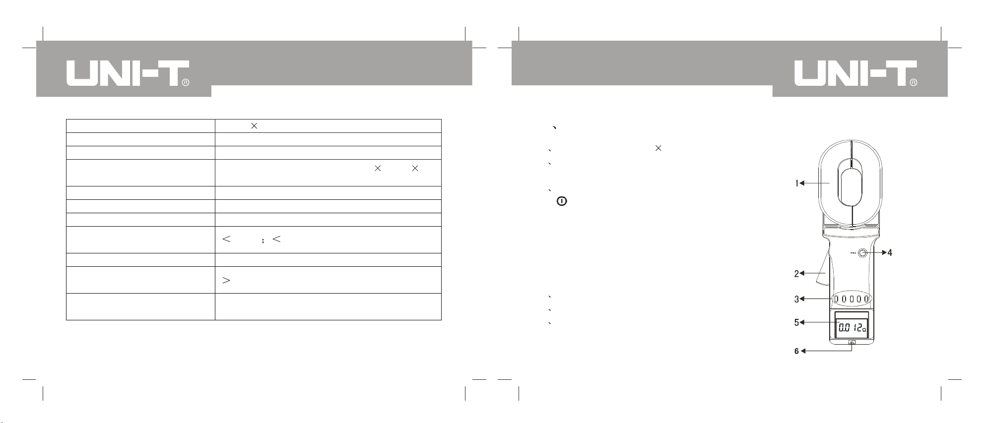
Unit UT276A User manual

P/N:110401103514

Contents
UT276A/278A OPERATING MANUAL
I Safety Instructions
II Product Overview
III Unpack and Check
IV Product Specification
1 Series Types
2 Range and Accuracy
3 Technical Specification
V Clamp Meter Structure
VI Liquid Crystal Display
1 Liquid Crystal Display
2 Instruction for Special Symbol
3 Display Demonstration
VII Operation Methods
1 Power-on
2 Power-off
3 Resistance Measurement
4 Current measurement
5 Data hold/unlock/store
1
3
4
5
5
6
7
9
10
10
11
12
16
16
18
18
21
22

1
I Safety Instructions
Thank you for purchasing the Clamp-on Ground Resistance of our company
and for the full use of the product, please:
Read the user manual carefully.
observe the operation notes listed in the manual.
Under no circumstances shall fail to pay attention to the safety in using the
clamp meter.
Pay attention to the stipulate measurement scope and operation environment.
The instrument shall apply to ground resistance testing instead of the current
of power frequency power wire, or it will affect the clamp's magnetic property
and the accuracy of ground resistance testing finally .
Pay attention to the labeled words on the surface board and backboard.
Before start it, pull the trigger once or twice to confirm the jaw of clamp can
close or open freely .
When starting it, don't pull the trigger and clamp any wires.
Clamp the objects being tested only after displaying the sign OL after
started the instrument.
UT276A/278A OPERATING MANUALUT276A/278A OPERATING MANUAL
7 Alarm Function Setting
8 Alarm Critical Value Inquiry
9 Data Wipe
10 Data Uploading to Computer
VIII Measurement Principles
1 Resistance Measurement Principle
2 Current Measurement Principle
IX Ground Resistance Measurement Method
1 Multi-point Ground System
2 Limited Point Ground System
3 Single Point Ground System
X On-site Application
1 Application of Power System
2 Application of Telecommunication System
3 Application of the building lightning protection ground system
4 Application of the gas station ground system
XI Notes about Ground Resistance Measurement
Appendix: loop Resistance Analysis
6 Data Inquiry 24
25
26
27
27
28
28
29
30
30
31
33
38
38
39
41
42
46
50

23
Contact surface of the clamp jaw shall keep clean and refrained from cleaning
by corrosive and coarse matters.
Refrain from any shock on the clamp meter , especially the junction surface of
the clamp jaw.
It is strongly recommended using our company's explosion-proof Clamp-on
Ground Resistance tester in dangerous occasions.
The explosion-proof product is prohibited to dismantle and replace the battery
in dangerous place.
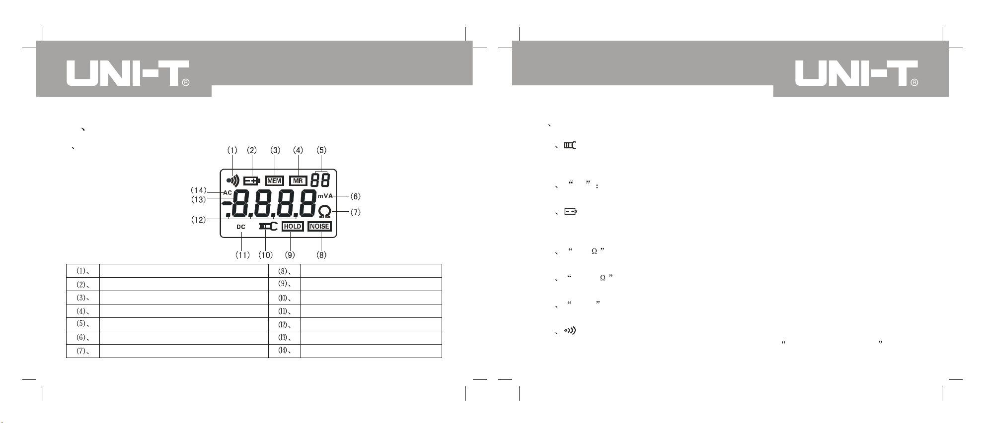
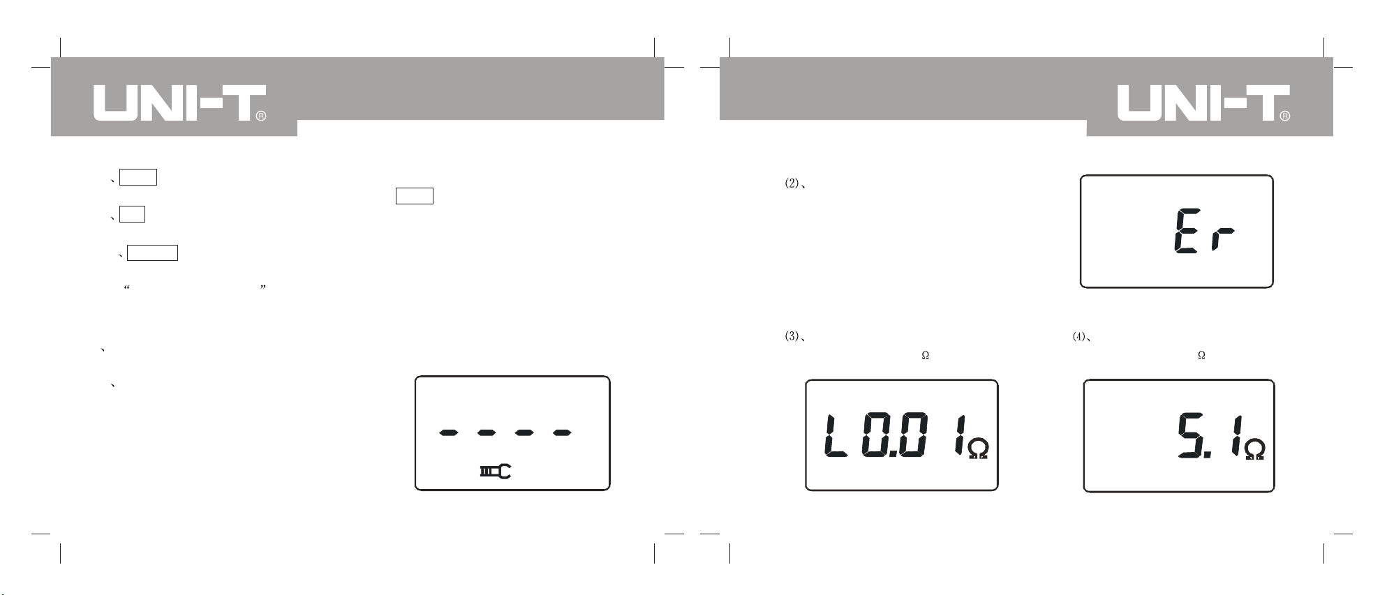
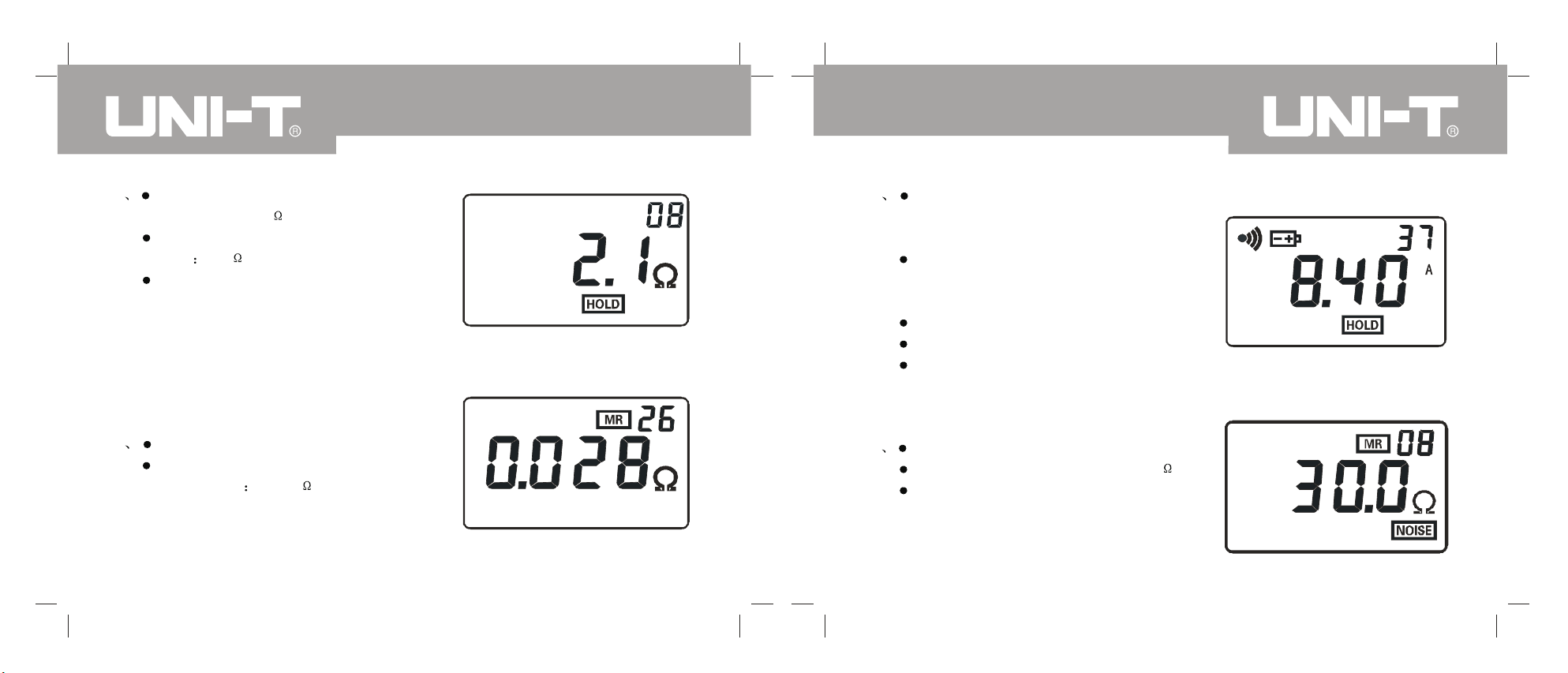
The clamp meter shall sound sporadically with light hum in measuring the
resistance, which is normal and shall be distinctive from the warning sound
beep--beep--beep-- .
Do not exceed the upper limits of the clamp meter in measuring the wire's
current.
Take out battery if do not use it for long time.
Dismantling, calibration and maintenance of the clamp meter shall be
conducted by the authorized qualified personnel.
If any danger might be resulted in continuation use by the inner reason of the
meter, stop using it immediately and pack it to the authorized qualified
institution to address the problem.
The contents labeled with * in the user manual shall be only applicable to
UT278A.
II Product Overview
The series of clamp-on ground resistance tester represents a significant
breakthrough of the traditional ground resistance measurement techniques and
apply widely to grounding resistance measurement in electricity,
telecommunication, meteorology, oilfield, architecture and industrial electric
equipment.
In measuring the ground system with loop, the series of clamp-on ground
resistance tester don't need to disconnect the ground down lead and any auxiliary
electrode, safe and fast, easy to use.
The series of clamp-on ground resistance tester can measure the grounding
problems with the traditional methods and apply to occasions traditional ways
can't measure as the tester measure the composite value of the grounding body
resistance and grounding down lead resistance.
UT276A 278A clamp-on ground resistance tester is the medium and high-end
UT276A/278A OPERATING MANUALUT276A/278A OPERATING MANUAL

45
Product in the UT270 clamp-on ground series, its uniqueness are:
No long time waiting for start up, enter into testing immediately .
The only one clamp-on ground resistance meter with RS232 port, uploading the
stored data to PC.
A breakthrough of the relay self-checking method, adopt the advance arithmetic
and digital IC processing techniques.
Solving the bulkiness of old product, and meeting the portable meter property .
Add the sound-light alarm function with beep--beep--beep--
Add the recognition indication function of interference signal with beep--beep--
beep-- .
Measurement scope has increased to 0.01 -1200 .
With 99-group storage data, lower energy consumption, and with working current
less 50mA in maximum start up.
III Unpack and Check
Unpack and take out the instrument, please check carefully if the following
attachment are complete or intact, if any lack or damage were found, please
contact with your supplier .
Meter
Test ring
Data up-loading software disk
RS232 communication wire
R6 AA size dry batteries
Meter box
User manual, warranty , qualification certificate
1
2
1
1(1.8m)
4
1
A set
Types Measuring
resistance
Measuring
current Storing data RS232 port Warning
function
Yes No
Yes
Yes Yes Yes
Yes Yes Yes Yes
IV Product Specification
1 Series Types
UT276A/278A OPERATING MANUALUT276A/278A OPERATING MANUAL

67
2 Range and Accuracy
Measurement mode Measurement Scope Resolution Accuracy
Resistance
*Current
3 Technical Specification
Resistance range
*Current range
Resistance resolution
*Current resolution
Data storage
RS232 port
Communication wire
Sound-light alarm
Scope of alarm critical value
setting
Power
Working temperature and
humidity
LCD
99groups
To upload stored data into the computer for
data analysis.
RS232communication wire with 1.8m long.
beep--beep--beep-- alarm press AL key to
control the on-off status.
Resistance 1-199 *current 1-499mA
6VDC (4 AA dry alkaline batteries )
-20 -55 10 RH-90 RH
4bit LCD digit display dimension
( 47mm 28.5mm)
UT276A/278A OPERATING MANUALUT276A/278A OPERATING MANUAL

50/60Hz (automatic)
Resistance measurement
frequency
Single measurement time
Outside magnetic field and
electric field
Full automatic shift
Structural characteristic Clamp CT
Double insulationProtection rate
Length, width and height 285mm 85mm
56mm
Clamp surface dimension
Clamp surface mass 1160g (inclusive of battery)
Clamp jaw stretch size
Clamp jaw dimension
89
65mm 32mm
28mm
Shift
40A/m 1V/m
0.5s
1KHz
*Frequency of the current
being measured
V Clamp Meter Structure
1 Long clamp head: 65 32mm
2 Trigger: control the closure and open
of clamp jaw
3 Function keys
ke key: (described as key POWER)
power on and off/exit
SAVE key: data inquiry/wipe data
AL alarm function key: alarm function
on/off
Left/right arrow key: resistance/current
mode conversion
4 HOLD key: hold/unhold display/store
5 LCD
6 RS232 port
UT276A/278A OPERATING MANUALUT276A/278A OPERATING MANUAL

10 11
VI Liquid Crystal Display
1 Liquid Crystal Display
Alarm symbol
Battery low voltage symbol
Full stored data symbol
Data inquiry symbol
Number of 2-bit stored data group
Current, voltage unit symbol
Resistance unit symbol
Noise signal
Data hold symbol
Clamp jaw open symbol
DC symbol
Decimal point
4-bit LCD digital display
(14). AC symbol
2 Instruction for Special Symbol
(2)Er power-on error symbol. It might be caused by the dirtiness of the
clamp jaw, please clean the clamp jaw surface.
(4)OL symbol, it means the resistance being measured exceeds the upper
limit of the clamp meter.
(5)L0.01 symbol, it means the resistance being measured exceeds the
lower limit of the clamp meter.
(6)OL A symbol, it means the current being measured exceeds the upper
limit of the clamp meter.
indicates that it might be artificial pull-off the trigger; or the clamp jaw has
been too dirty to measure, requiring clamp jaw cleaning.
(1) clamp jaw open symbol. It shall display when the clamp jaw is open. It
the symbol would appear and replace battery in time or the measurement
accuracy couldn't be guaranteed.
(3) battery low voltage symbol. When the battery voltage is lower than 5.3V ,
it will flicker and the meter will sound sporadic beep--beep--beep-- .
(7) Alarm symbol, when the measured value exceed the alarm critical value,
UT276A/278A OPERATING MANUALUT276A/278A OPERATING MANUAL

12 13
(8)MEM full stored data symbol, when the stored data has reached 99 groups
and can't store data anymore, the symbol MEM shall flicker.
Of stored data.
(9)MR Data inquiry symbol, it shall appear in inquiring data and indicate the No.
loop being measured, the symbol shall flicker and the meter sound sporadic
beep--beep--beep-- , the measurement accuracy of the time can't be
guaranteed.
(10)NOISE Symbol, when there are quite big interference current to the earth
3 Display Demonstration
(1)as clamp jaw is open, it can't measure.
(It might be caused by the dirtiness of
the clamp jaw, please clean the clamp
jaw surface.)
power-on error indication Er(Error)
(It might be caused by the dirtiness
of the clamp jaw , please clean the
clamp jaw surface.)
resistance of the loop being
measured <0.01
resistance of the loop being
measured is 5.1
UT276A/278A OPERATING MANUALUT276A/278A OPERATING MANUAL

14 15
(5)resistance of the loop being
measured is 2.1,
hold the present measurement
value 2.1,
store automatically as the No.08
group data.
(6)inquiry the No.26group stored data
resistance of the loop being
measured is 0.028
(7)start alarm function and the current
being measured exceed the set
alarm critical value
battery low voltage display and the
measurement accuracy can't be
guaranteed.
current being measured is: 8.40A
hold the present display value
store the present hold value as the
No 37 group data.
(8)inquiry No 08 group stored data
resistance being measure is: 30.0
the data is measured under strong
interference signal
UT276A/278A OPERATING MANUALUT276A/278A OPERATING MANUAL

16 17
VII Operation Methods
1 Power-on
Notes
When starting it, don't pull the trigger , open the clamp jaw and clamp any wires.
pull the trigger, open the clamp jaw and clamp wires only after power-on and
display the Ol
Before power-on, pull the trigger once or twice to confirm the clamp jaw can
close or open freely .
When power-on, keep the clamp meter static, no turning and no force on the
clamp jaw or the measurement accuracy can't be guaranteed.
Press the key POWER, check the LCD automatically and symbols shall appear
as shown in picture1. Meanwhile, the meter calibrate automatically, after power-on,
it shall display OL and enter automatically into the resistance measurement
mode, as shown in picture2. If automatic calibration under improper power-on,
the meter will display the symbol Er indicating error occurs in power-on, as
shown in picture3.
Picture 1Picture2 Picture 3
The power-on error might be resulted by the bad
closure of clamp jaw or by the dirt on the clamp
jaw surface, please clean it.
Picture 4
If after the power-on self check, it appears a big
resistance instead of OL as shown in
picture 4. It might be resulted by the bad closure
of clamp jaw or by the dirt on the metal surface,
please clean it.
If the result is correct in detection by the test ring, it represents that the clamp
meter have big error just in measuring high resistance (>100 ), and remain
UT276A/278A OPERATING MANUALUT276A/278A OPERATING MANUAL

18 19
original accuracy in measuring low resistance, user can use it with assurance.
2 Power-off
Press key POWER to power-off after power-on.
After working 5 minutes, the LCD shall flicker continuously about 30seconds and
then power-off to reduce battery consumption. Press key POWER to delay power
-off, the clamp meter shall continue working.
Under the HOLD status, press key HOLD to exit the status and press key
POWER to power-off.
Under setting alarm critical value status, it is required to press key POWER or
key AL 3 seconds to exit the status and press key POWER to power off.
3 Resistance Measurement
If display OL after power-on self check, you can measure the resistance.
Pull the trigger and open clamp jaw, clamp the loop being measured to read the
resistance value.
Users are required to test by random test ring as shown in picture 5.
The displayed value should be the same with
standard value on the test ring (10.0), which
is the value under temperature 20 .it is normal
if there is a decimal difference between them,
for instance, standard value of the test ring is
10.0; the displayed value is 9.9 or 10.1.
Display OL it means the resistance being
measured exceed the upper limit of clamp
meter, as shown in picture 2.
Picture 5
UT276A/278A OPERATING MANUALUT276A/278A OPERATING MANUAL

20 21
Display L0.01 it means the resistance being measured exceed the lower limit
of clamp meter, as shown in picture6.
resistance being measured exceed the resistance alarm critical value.
POWER to power-off.
Under setting alarm critical value status, it is required to press key POWER or
key AL 3 seconds to exit the status and continue to measure.
*Under the current test mode, press key covert to the resistance test mode.
Flicker display symbol with sporadic beep--beep--beep-- it means the
Under the HOLD status, press key HOLD to exit the status and press key
Under the MR status, press key SAVE to exit the status and continue to measure.
Picture 6
4 Current measurement
Notes:
the meter is mainly used for ground resistance test and the current measurement
shall be only applicable to the current test on the ground wire but the power line
or affect the magnetic property of the clamp head and finally affect the ground
resistance test accuracy .
After power-on self check, clamp meter shall enter into the resistance
measurement mode. After display the OL ", press key A, clamp meter enter into
current measurement mode, displaying AC 0.00m as shown in picture 7.
Pull the trigger, open the clamp jaw and clamp on the wire to read the current
value.
OL on the clamp meter , it means the current being measured exceed the
upper limit of clamp meter, as shown in picture 8.
Flicker display symbol with sporadic beep--beep--beep-- , it means the
current being measured exceed the current alarm critical value.
UT276A/278A OPERATING MANUALUT276A/278A OPERATING MANUAL

22 23
Picture 8
Picture 7
Under the HOLD status, press key HOLD to exit the status and continue to
measure.
Under the MR status, press key SAVE to exit the status and continue to measure.
Under setting alarm critical value status, it is required to press key POWER or
key AL 3 seconds to exit the status and continue to measure.
Under the resistance test mode, press key A covert to the current test mode.
5 Data hold/unlock/store
Under the test mode, press key HOLD to hold the present value and when
displaying the symbol HOLD, the hold value could be set as a group of data and
numbered automatically orderly and be stored. Press key HOLD to cancel hold,
the symbol HOLD would disappear and continue to measure. Operate as the
above steps; you can store 99 groups of data. If the memory is full, the symbol
MEM will flicker .
As shown in picture 9, hold the measured resistance 0.016 , and store it as the
No 01group data.
As shown in picture 10, hold the measured current 278mA and store it as the No
99 group data, then the memory is full, the symbol MEM will flicker.
Picture 9 Picture 10
UT276A/278A OPERATING MANUALUT276A/278A OPERATING MANUAL

24 25
Under the data inquiry mode, press key SAVE to exit the data inquiry and hold,
store the data.
Under setting alarm critical value status, it is required to press key POWER or
key AL 3 seconds to exit the status and continue to hold and store data.
The stored data would not lose when power-on after power off the meter.
6 Data Inquiry
Press key SAVE to enter into the stored data inquiry mode and display the No 01
group stored data, as shown in picture 1 1. Then press the right arrow key , inquiry
upward stored data or press the left arrow key to inquiry downward all stored data.
If no stored data, it will display as shown in picture 12.
Picture 11 Picture 12
Under setting alarm critical value status, it is required to press key POWER to exit
the status and press key SAVE to enter into the stored data inquiry mode.
7 Alarm Function Setting
Under the test mode, press key AL to open or close the alarm function.
Under the test mode, press key AL 3 seconds to enter into the alarm critical value
setting function, and the highest digit number shall flicker; set the highest digit as
shown in picture 13 and 14. Press key AL to convert the number on high digit and
low digit. When the present digit number is flickering, press right and left arrow
key to change the number 0,1, 9 after setting all numbers, press key AL 3
seconds to confirm the set alarm critical value. It means it is able to operate the
alarm function and then back to the measurement mode automatically. If the load
is bigger the alarm critical value, the meter shall display alarm symbol with
sporadic sounds beep--beep--beep-- .
During the set process, press key POWER to exit the alarm critical value setting
function and back to the measurement status, without changing the previous set
value.
Under the data inquiry mode, press key SA VE to exit the mode and to set the
alarm critical value.
UT276A/278A OPERATING MANUALUT276A/278A OPERATING MANUAL

26 27
Flicker Flicker
Picture13. Set the resistance
alarm critical value
Picture14. Set the current
alarm critical value
8 Alarm Critical Value Inquiry
Under the test mode, press key AL 3 seconds to inquire the alarm critical value,
and the highest digit number shall flicker and each time inquired is the previous
set value. Press key AL 3 seconds or key POWER to exit and check, back to
measurement status. As shown in picture 15, the previous set resistance alarm
critical value is 20 .
Flicker
Picture 15
9 Data Wipe
Under the data inquiry mode, press key SA VE+POWER, automatically wipe
all stored data, after it , meter shall display as shown in the picture 12, and all
wiped data shall not able to recover .
10 Data Uploading to Computer
Connect the meter host with computer with the RS233 communication wire
deployed with the meter and the meter shall power on and operate software,
select history check, and read, store and print the history data. The history
data could be saved as Txt text or in the Excel format.
UT276A/278A OPERATING MANUALUT276A/278A OPERATING MANUAL

28 29
VIII Measurement Principles
1 Resistance Measurement Principle
Basic principle of the clamp-on ground
resistance meter in measuring the ground
resistance is measuring the loop
resistance (detailed in appendix).
Refer to the following picture; clamp jaw
of the clamp is composed of voltage coil
and current coil. The meter measures E
and I, and know the measured resistance
R by the following formula.
R=E/I
2 Current Measurement Principle
The basic principle of UT278A clamp-on ground resistance meter is the same with
that of current transformer measurement.
The AC current I of the measured wire, passing through the current magnetic ring
and current coil on the clamp jaw, produce the induction current I1 which could
be measured by the clamp meter and know the measured current I by the
following formula:
UT276A/278A OPERATING MANUALUT276A/278A OPERATING MANUAL
Conductor being measured

30 31
Of which: n is the transformer ratio coefficient between secondary and primary coil.
IX Ground Resistance Measurement Method
1 Multi-point Ground System
Multi-point ground system (ex. Electricity Transmission System tower grounding,
communication cables grounding system, some buildings etc.) are connected by
the overhead ground wires and form into the ground system. As shown in the
following picture, when measuring by the clamp meter, the equivalent circuit shall
be shown as follows:
Of which, R1 is the estimated ground resistance and R0 is the equivalent
resistance of all other towers ground resistance in parallel.
From the aspect of strict ground theory , as the existence of the so called mutual
resistance , R0, in general electrical engineering meaning, is not the parallel
value (slightly bigger than that of general electrical engineering meaning), but
ground hemisphere of each tower is much smaller than the distance between
towers and the great number of ground points, R0 is much smaller than R1. Thus,
it is reasonable to speculate R0=0 from the engineering aspect and the resistance
we measured should be R1.
After many comparison tests between tests under different environment,
occasions and traditional ways, the above speculation is fully reasonable.
2 Limited Point Ground System
The circumstance is quite common, for instance, some towers are connected with
each other by the over head ground wire; and some building's ground is not an
independent ground net but several ground bodies connected with each other by
wires.
Under this circumstance, regarding R0 in the above picture as 0 shall result in
UT276A/278A OPERATING MANUALUT276A/278A OPERATING MANUAL

R1T
RN R3
R2
R1 1
......
1 1
1 =
+ + +
+
T
N
R
RRR
R2
31
21
......
11
1=
+++
+
NT
N
NR
RRR
R=
+++
+
- )1(21
1
......
11
1
32 33
great errors.
Owing to the same reason, we neglect the impact of mutual resistance and
calculate the equivalent resistance of ground resistance in parallel from the
general meaning. Thus, for ground system of N N is small, but bigger than 2
ground bodies, we can list out N formula:
Of which, R1 R2 .RN is the ground resistance of N ground bodies we need
to solve.
R1T R2T RNT are respectively the resistance measured on each ground
branch circuit by clamp meter.
This is nonlinear equations with N unknown and N equations. It has certain
solution, but which is difficult to solve by manual operations and even impossible
when N is quite big.
Purchasing the limited point ground system calculating program software from
our company, user shall be able to solve it by using an of fice computer or laptop.
Principally, except for the neglect of mutual resistance, the method would not
result in any measurement error brought by neglecting R0.
Users need to pay attention that: the number of connected ground bodies in your
ground system shall be exactly equal to that of measurement value for program
calculation and the program shall output the same number of ground resistance
value.
3 Single Point Ground System
From the test principle, UNIT series clamp meter can only be used to measure
loop resistance but the single point ground. However , user can make a loop to
test by using a test line and ground polarity near the ground system. Two methods
of measuring single point ground by clamp meter are introduce in the following
and the method could be applicable to occasions that traditional voltage-current
UT276A/278A OPERATING MANUALUT276A/278A OPERATING MANUAL

34 35
method fail to measure.
(1)Two -point method
As shown in the following picture, find an independent ground body RB with good
ground near the ground body RA being measured ex. adjacent metal running
water pipe, metal fire hydrant, building etc.and connect RA with RB by a test line.
Test line
As resistance measured by the clamp meter is the parallel value of 2 ground
resistance and test line resistance,
RT=RA+RB+RL.
Of which, RT is the resistance measured by clamp meter and RL is the resistance
of test line.
Resistance RL could be measured by clamp meter by connecting the test line
end to end. If measurement value of clamp meter is smaller than the allowable
value of ground resistance, ground resistance of the two ground bodies shall be
qualified.
(2)Three-point method
As shown in the following picture, find two independent ground bodies RB and
RC near the ground body RA being measured. If no existing independent ground
body, make 2 auxiliary ground polarities with 3-5m distance between them and
about 0.7m depth each.
Step1, connect RA and RA with a test line, as shown in the following picture, and
read the first data R1 by clamp meter .
UT276A/278A OPERATING MANUALUT276A/278A OPERATING MANUAL
This manual suits for next models
1
Table of contents
Other Unit Test Equipment manuals

Unit
Unit UPO3000E Series User manual

Unit
Unit UTD1000L Series User manual

Unit
Unit UTD2025C User manual

Unit
Unit UT528 User manual

Unit
Unit UPO1000 Series User manual

Unit
Unit UPO2102 User manual

Unit
Unit UTD2025 series User manual

Unit
Unit UT-513A User manual

Unit
Unit UTD4000 Series User manual

Unit
Unit UT5300X+ Series User manual
Popular Test Equipment manuals by other brands

MARTINDALE
MARTINDALE MTL10 instruction manual

Extech Instruments
Extech Instruments BR90 user manual

Rebel TOOLS
Rebel TOOLS MIE-RB-468 manual

Tokyo Gas Engineering Solutions Corporation
Tokyo Gas Engineering Solutions Corporation SA3C50A Operation manual

Conrad
Conrad 17 40 92 operating instructions

Neilsen
Neilsen CT4691 quick start guide