manuals.online logo
Brands
  1. Home
  2. •
  3. Brands
  4. •
  5. urmet domus
  6. •
  7. Security Sensor
  8. •
  9. urmet domus 1033/013 User manual

urmet domus 1033/013 User manual

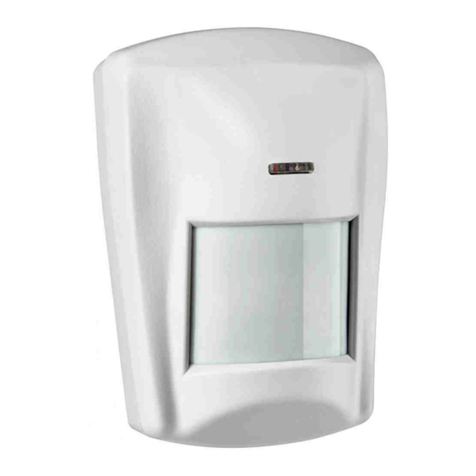
RIVELATORE IR CON PET IMMUNITY
IR DETECTOR WITH PET IMMUNITY
Sch./Ref. 1033/013
Copertura / Cover
CARATTERISTICHE TECNICHE
Pet Immunity con selezione della dimensione dell’animale su due livelli
Tensione nominale di alimentazione: ...12V +/- 3V
Assorbimento a 12 V : .......................10mA nom. 17mA max
Copertura totale: ..................................90° per 12 m
Zone sensibili: ......................................18 su 4 piani
Opto Relè di allarme:............................100mA / 24V
Tamper antimanomissione: ..................100 mA / 30V
Tempo Allarme:....................................3 sec
Temperatura di funzionamento:............-10°C ÷ +55°C
Umidità Ambientale: .............................95%
MTBF Teorico: .....................................120.000 ORE
Dimensioni (h x l x p):...........................75 x 60x 45 mm
Peso:....................................................65 g
Livello prestazione:...............................EN50131-2-2 Classe II, Grado 2
ACCESSORI OPZIONALI
•Snodo per rivelatori da interno sch. 1033/119 *
AVVERTENZE
•Installare il sensore su superfici rigide, prive di vibrazioni, ad una altezza
compresa tra 2 e 2,3 metri facendo riferimento ai diagrammi di rilevazione.
•Evitare il posizionamento del sensore vicino a fonti di calore o alla luce diretta
del sole.
•Evitare che esistan
o, a causa di mobili, scaffalature, ecc. zone cieche
nell’area protetta entro cui possa muoversi l’intruso. Evitare che gli animali,
arrampicandosi su un qualsiasi supporto (mobili, scale, ecc.), possano
interessare le zone sensibili della lente predisposte per la rivelazione a lunga
distanza (vedi figura 2) oppure interessare zone limitrofe al sensore.
•Non installare il sensore all’esterno.
•Nel caso di installazioni ad altezze superiori ai 2,2 metri si consiglia l’utilizzo
dello snodo opzionale (si vedano oltre i dettagli).
INSTALLAZIONE
INSTALLAZIONE SENZA SNODO
Per rimuovere il coperchio del sensore
togliere la vite di chiusura (se inserita)
e premere con un cacciavite sul dente
di fissaggio, verso l’interno della
feritoia. Per togliere il circuito
stampato allargare uno dei ganci E1-
E2 (Fig. 3).
Attenzione: non toccare con le dita
il sensore piroelettrico.
Fondo plastico del sensore (Fig. 3):
•A1-A2 = PREDISPOSIZIONI PER IL
FISSAGGIO AD ANGOLO
•B1-B2 = PREDISPOSIZIONI PER IL FISSAGGIO SU SUPERFICIE PIANA
•C1-C2-C3 = PREDISPOSIZIONI PER IL PASSAGGIO CAVI
Fissare il fondo plastico alla parete con le viti e i tasselli, avendo cura che le
teste delle stesse non tocchino la scheda elettronica. Rimontare il circuito sul
fondo plastico.
INSTALLAZIONE CON SNODO - non inclinare verso il basso per non
perdere l’immunità agli animali
Per il montaggio dello snodo, aprire le apposite
predisposizioni a sfondamento “D” (fissaggio snodo) e
“C3” (passaggio cavi snodo), mostrato in Fig. 3 ed
assemblare lo snodo; è importante, terminato
l’orientamento, bloccare il movimento dello snodo serrando a fondo la vite
fornita a corredo dello stesso. Il manuale completo dello snodo è disponibile sul
sito www.urmet.com.
TECHNICAL CHARACTERISTICS
Pet Immunity with two-level animal size selection
Nominal power voltage:................... 12V +/- 3V
Consumption at 12 V : .................. 10mA nom. 17mA max.
Total IR coverage:........................... 90° at 12 m
Sensitive zones:.............................. 18 on 4 floors
Alarm relay opto:............................. 100mA / 24V
Tamperproof switch:........................ 100 mA / 30V
Alarm time:...................................... 3 sec
Working temperature range:............ -10°C – +55°C
Ambient humidity:............................ 95%
Theoretical MTBF:........................... 120,000 HOURS
Dimensions (h x w x d): ................... 75 x 60x 45 mm
Weight:............................................ 65 g
Performance level: .......................... EN50131-2-2 Class II, Degree 2
OPTIONAL ACCESSORIES
•Detectors brackets Ref. 1033/119 *
CAUTIONS
•Install the sensor on rigid, vibration-free surfaces at a height comprised
between 2 and 2.3 metres making reference to the detection diagrams
•Avoid positioning the sensor close to sources of heat or direct sunlight.
•Avoid the creation of blind areas caused by furniture, shelving etc. in the
protected area in which an intruder could move about. Do no allow
animals to climb up anything (furniture, ladders etc.) and disturb the
sensitive part of the lens set for long-distance detection (see figure 2) or
the areas close to the sensor.
•Do not install the sensor outdoors.
•In case of installations at heights greater than 2.2 metres, it is advisable to
use the optional bracket (see details further on).
INSTALLATION
INSTALLATION WITHOUT
BRACKET
To remove the sensor cover,
remove the fastening screw (if
inserted) and press with a
screwdriver on the fastening
screw towards the inside of the
slot. Widen one of the hooks E1-
E2 to remove the printed circuit
(Fig. 3).
Warning: do not touch the
pyroelectric sensor with your
fingers.
Plastic bottom of the sensor (Fig.
3):
•A1-A2 = SET-UP FOR FIXING IN CORNER
•B1-B2 = SET-UP FOR FIXING ON FLAT SURFACE
•C1-C2-C3 = SET-UP FOR CABLE PASSING
Fix the plastic bottom to the wall with screws and anchor bolts being careful
that they do not touch the electronic board. Refit the circuit onto the plastic
bottom.
INSTALLATION WITH BRACKET - do not incline
downwards to maintain the pet immunity
function.
To install the bracket, open the specific cut-out
areas "D" (bracket fastening) and "C3" (bracket
cable passage) shown in Fig. 3, and assemble the bracket. Importantly,
after orienting, block the movement of the bracket by tightening the screw
provided with the bracket. The complete user manual of the bracket is
available on the website www.urmet.com.
EN
IT
LBT20247
DS1033-145D
Fig. 1
Fig. 2
Fig. 3
DESCRIZIONE MORSETTIERA
IDa non utilizzare
+ - Alimentazione 12V
NC TAMP Contatto N.C.
NC ALL Contatto N.C. del relè di allarme
DESCRIZIONE DIPSWITCH
DI FABBRICA I DIP SWITCHES SONO TUTTI OFF
N.B. ogni volta che un Dip Switch viene selezionato il rivelatore farà un SELF
TEST di 15" durante il quale si dovrà rimontare il frontalino ed allontanarsi dal
sensore.
DIP1

PET
ON: BASSA OFF: ALTA
DIP2

LED PER PROVA PORTATA
ON: DISABILITA OFF: ABILITA
FUNZIONI SETTABILI CON DIPSWITCH
PET (R.H.) – Pet Immunity 12 Kg - DipSwitch N° 1 in pos. OFF
Con questa impostazione il sensore ha la massima performance ed il
massimo campo di rilevazione operativo possibili.
Si ha un’immuni
tà agli animali fino a 12Kg di peso, in ambienti con
temperatura maggiore di 10°C.
Con temperature ambientali maggiori di 20°C si può usare questo settaggio
per animali fino a 18Kg di peso.
PET (R.L.) – Pet Immunity 20 Kg - DipSwitch N° 1 in pos. ON
Con questa impostazione il sensore riduce la propria portata di rilevazione a
10mt.
Si ha un’
immunità agli animali fino a 20Kg di peso, in ambienti con
temperatura maggiore di 10°C.
Con temperature ambientali maggiori di 20°C si può usare questo settaggio
per animali fino a 25Kg di peso.
LED - DipSwitch N° 2 in pos. OFF
Attiva le visualizzazioni di rilevazione.
LED - DipSwitch N° 2 in pos. ON
Disattiva le visualizzazioni di rilevazione, mantenendo abilitate le
visualizzazioni relative alle memorie.
PRIMA ALIMENTAZIONE
Fornita l’alimentazione, il sensore entra nella fase di inizializzazione, durante
la quale il LED lampeggia. Dopo questa fase (che dura 60 secondi circa), il
sensore diventa operativo.
Procedere con il walk test in questo modo:
Applicare il frontale plastico e, a LED spento, muoversi nell’area di pertinenza
del sensore verificando la rilevazione del PIR tramite il LED. Constatando
così che non vi siano zone d'ombra.
* Lo snodo per rivelatori da interno sch. 1033/119 e la funzione Pet Immunity
non sono certificati IMQ
DIRETTIVA 2012/19/UE DEL PARLAMENTO EUROPEO E DEL
CONSIGLIO del 4 luglio 2012 sui rifiuti di apparecchiature elettriche ed
elettroniche (RAEE).
Il simbolo del cassonetto barrato riportato sull’apparecchiatura o
sulla sua confezione indica che il prodotto alla fine della propria vita
utile deve essere raccolto separatamente dagli altri rifiuti. L’utente
dovrà, pertanto, conferire l’apparecchiatura giunta a fine vita agli
idonei centri comunali di raccolta differenziata dei rifiuti
elettrotecnici ed elettronici. In alternativa alla gestione autonoma è possibile
consegnare l’apparecchiatura che si desidera smaltire al rivenditore, al
momento dell’acquisto di una nuova apparecchiatura di tipo equivalente.
Presso i rivenditori di prodotti elettronici con superficie di vendita di almeno
400 m2 è inoltre possibile consegnare gratuitamente, senza obbligo di
acquisto, i prodotti elettronici da smaltire con dimensione massima inferiore a
25 cm. L’adeguata raccolta differenziata per l’avvio successivo
dell’apparecchiatura dismessa al riciclaggio, al trattamento e allo smaltimento
ambientalmente compatibile contribuisce ad evitare possibili effetti negativi
sull’ambiente e sulla salute e favorisce il reimpiego e/o riciclo dei materiali di
cui è composta l’apparecchiatura.
TERMINAL BOARD DESCRIPTION
INot to be used
+ - 12V power
NC TAMP NC contact
NC ALL NC alarm relay contact
DIP SWITCH DESCRIPTION
ALL DIP SWITCHES ARE SET TO OFF BY DEFAULT
N.B. when a DIP SWITCH is positioned the Detector will perform a 15 Sec
SELF TEST, during this period mount the front cover and move away from the
detector.
DIP1

PET
ON: LOW OFF: HIGH
DIP2

RANGE TEST LED
ON: DISABLE OFF: ENABLE
FUNCTIONS WHICH CAN BE SET WITH THE DIP SWITCHES
PET (R.H.) – Pet Immunity 12 Kg - DipSwitch N° 1 in pos. OFF
With this setting, the sensor has maximum performance and the maximum
possible operative detection field.
It provides immunity for pets weighing up to 12 kg in environments with
ambient temperature higher than 10°C.
This setting may be used for pets weighing up to 18 kg in environments with
ambient temperature higher than 20°C.
PET (R.L.) – Pet Immunity 20 kg - Dip Switch in ON position
The detection range of the sensor is reduced to 10 metres with this setting.
It provides immunity for pets weighing up to 20 kg in environments with
ambient temperature higher than 10°C.
This setting may be used for pets weighing up to 25 kg in environments with
ambient temperature higher than 20°C.
LED - Dip Switch 2 in OFF position
Activates the detection views.
LED - Dip Switch 2 in ON position
Deactivates the detection views maintaining the memory views enabled.
FIRST POWER-ON
When power is connected the sensor will start an initialising step during which
the LED will blink.The sensor will start working after this step (which lasts
approximately 60 seconds).
Proceed with the walk test, as follows:
Apply the plastic front and, with LED off, move in the area verifying the
detections of PIR through the LED. In this way you can verify that there aren't
shadow zones.
* The bracket for detectors Ref. 1033/119 and the Pet Immunity function are
not IMQ certified.
DIRECTIVE 2012/19/EU OF THE EUROPEAN PARLIAMENT AND OF THE
COUNCIL of 4 July 2012 on waste electrical and electronic equipment
(WEEE).
The symbol of the crossed-out wheeled bin on the product or on its
packaging indicates that this product must not be disposed of with
your other household waste.
Instead, it is your responsability to dispose of your waste equipment
by handing it over to a designated collection point for the recycling of waste
electrical and electronic equipment. The separate collection and recycling of
your waste equipment at the time of disposal will help to conserve natural
resources and ensure that it is recycled in a manner that protects human
health and the environment.
For more information about where you can drop off your waste equipment for
recycling, please contact your local city office, your household waste disposal
service or the shop where you purchased the product.
PET
LED
PET
LED
http://www.urmet.com -e-mail: info@urmet.com
Via Bologna 188/C - 10154 TORINO (ITALY) Tel. 011.24.00.000 / Fax
011.24.00.300-323 – Assistenza tecnica / Technical assistance +39.011.23.39.810
Made in Italy
INFRAROT-MELDER PET IMMUNITY
Ref. 1033/013
ABDECKUNG
TECHNISCHE EIGENSCHAFTEN
Haustierimmunitätsfunktion mit Auswahl der Haustiergröße auf zwei Ebenen
Nennspannung:....................................12V +/- 3V
Stromaufnahme 12 V : ........................10mA nom. max. 17mA
Reichweite: .........................................12 m
Deckung IR: .........................................90°
Empfindliche Bereiche:.........................18 von 4 Ebenen
Opto-Alarmrelais: .................................100 mA / 24V
Tamper Sabotageschutz: .....................100 mA / 30V
Alarmzeit: .............................................3 s
Betriebstemperatur:..............................-10°C ÷ +55°C
Umgebungsfeuchtigkeit:.......................95 %
Theoretische MTBF:.............................120.000 Stunden
Abmessungen (H x B x T): ...................75 x 60 x 45 mm
Gewicht:...............................................65 g
Leistungsniveau: EN50131-2-2 KLASSE II Grad 2
ZUBEHÖR AUF ANFRAGE
Gelenke für Melder ref. 1033/119 *
ZUR BEACHTUNG
•Der Sensor wird an festen, erschütterungsfreien Oberflächen in einer Höhe
von 2 bis 2,3 Metern installiert. Dabei sind die üblichen Messungsdiagramme
zu berücksichtigen, so dass der Sensor Bewegungen erfasst, die den
geschützten Bereich durchqueren und das Mikrowellenmodul die sich
nähernden Bewegungen erfasst.
•
Der Sensor sollte nicht in der Nähe von Wärmequellen angebracht oder
direkter Sonneneinstrahlung ausgesetzt werden.
•Vermeiden Sie, dass aufgrund von Möbeln, Regalen, usw. blinde Bereiche im
geschützten Abschnitt vorliegen,
in denen sich ein Eindringling bewegen
kann. Vermeiden Sie, dass Tiere auf jegliche Einrichtungen (Möbel, Leitern,
usw.) klettern und damit in die empfindlichen Bereich der Linse zur Erfassung
aus weiter Entfernung (sh. Abb. 2) bzw. die an den Sensor angrenzenden
Bereiche gelangen können.
•Installieren Sie den Sensor nicht im Freien.
•Bei Installationen in Höhen über 2,2 Metern empfiehlt sich die Verwendung
des optionalen Gelenks (siehe weitere Details).
INSTALLATION
INSTALLATION OHNE GELENK
Um den Deckel des Sensors zu
entfernen, die Verschlussschraube
entfernen (wenn sie eingesetzt ist)
und mit einem Schraubendreher
auf den Einrastzahn zum Inneren
des Schlitzes drücken. Zum
Entfernen der Leiterplatte einen der
Haken E1-E2 abhebeln (Abb. 3).
Achtung: den pyroelektrischen
Sensor nicht mit den Fingern
berühren.
Kunststoffboden des Sensors (Abb.
3):
•A1-A2 = VORBEREITUNGEN
FÜR DIE WINKELBEFESTIGUNG
•B1-B2 = VORBEREITUNGEN FÜR DIE BEFESTIGUNG AN EINER EBENEN
FLÄCHE
•C1-C2-C3 = VORBEREITUNGEN FÜR DEN KABELDURCHGANG
Befestigen Sie den Kunststoffboden mit den Schrauben und Dübeln an der
Wand und achten Sie darauf, dass deren Köpfe die Elektronikplatine nicht
berühren. Bauen Sie den Schaltkreis wieder auf der Kunststoffunterseite
zusammen.
INSTALLATION MIT GELENK - Nicht nach unten
ki
ppen, um die Immunität gegenüber Tieren
nicht zu verlieren.
Um die Verbindung zusammenzubauen, öffnen Sie
die speziellen Ausbrechanschlüsse „D“
(Verbindungsbefestigung) und „C3“ (Verbindungskabeldurchführung) (siehe
Abb. 3) und montieren Sie die Verbindung. Nach der Ausrichtung ist es
wichtig, die Bewegung des Gelenks durch vollständiges Anziehen der
mitgelieferten Schraube zu blockieren. Das vollständige
Verbindungshandbuch ist auf der Website www.urmet.com verfügbar.
BESCHREIBUNG DER KLEMMENLEISTE
INicht zu verwenden
+ - 12 V-Versorgung
NC TAMP NC-Kontakt
NC ALL NC-Kontakt des Alarmrelais
BESCHREIBUNG DER DIP-SWITCHES
WERKSEITIG STEHEN ALLE DIP-SWITCHES AUF OFF
Hinweis: Jedes Mal, wenn ein DIP-
Schalter ausgewählt wird, führt der
Detektor einen 15-Zoll-SELBSTTEST durch, bei dem Sie die Frontplatte
wieder zusammenbauen und sich vom Sensor entfernen müssen.
DIP1

PET
ON: NIEDRIG OFF: HOCH
DIP2

LED FÜR REICHWEITENPROBE
ON: DEAKTIVIERT OFF: AKTIVIERT
MIT DEN DIP-SWITCHES EINSTELLBARE FUNKTIONEN
PET (R.H.) – Pet Immunity 12 Kg - DipSwitch N° 1 in pos. OFF
Bei dieser Einstellung erbringt der Sensor die maximale Leistung und
erreicht den maximal möglichen Erfassungsbereich.
Der Schutz gegen Tiere wird bis zu einem Gewicht von 12 kg in
Umgebungen mit einer Temperatur von mehr als 10°C gewährleistet.
Bei Umgebungstemperaturen von über 20°C kann diese Einstellung für
Tiere bis zu einem Gewicht von 18 kg verwendet werden.
PET (R.L.) – Pet Immunity 20 Kg - DipSwitch N° 1 in pos. ON
Bei dieser Einstellung verringert der Sensor seine Erfassungsreichweite auf
10 m.
Der Schutz gegen Tiere wird bis zu einem Gewicht von 20 kg in
Umgebungen mit einer Temperatur von mehr als 10°C gewährleistet.
Bei Umgebungstemperaturen von über 20°C kann diese Einstellung für
Tiere bis zu einem Gewicht von 25 kg verwendet werden.
LED - DipSwitch N° 2 in pos. OFF
Aktiviert die Anzeigen der Erfassung.
LED - DipSwitch N° 2 in pos. ON
Deaktiviert die Anzeigen der Erf
assung, erhält jedoch die Anzeigen in
Bezug auf die Speicher.
DE
LBT20247
DS1033-145D
Abb. 1
Abb. 2
Abb. 3
PET
LED
ERSTE STROMVERSORGUNG
Bei Stromversorgung tritt der Sensor in die Initialisierungsphase ein, während
der die LED blinkt. Nach dieser Phase (die etwas 60 Sekunden dauert) wird der
Sensor operativ.
Den Leistungstest (Walk Test) wie folgt ausführen:
Die Kunststoffblende anbringen und sich bei ausgeschalteter LED im vom
Sensor kontrollierten Bereich bewegen und die Messung des PIR über die
GELBE LED überprüfen.
Auf diese Weise stellen sie sicher, dass es keine Grauzonen gibt.
* Die Gelenke für Melder ref. 1033/119 und die Pet Immunity-Funktion sind
nicht IMQ-zertifiziert.
KORREKTE ENTSORGUNG VON ALTGERÄTEN (Elektroschrott)
Diese Kennzeichnung auf dem Produkt, den Zubehörteilen oder der
Dokumentation weist darauf hin, dass das Produkt und die
elektronischen
Zubehörteile nicht mit anderem Hausmüll entsorgt
werden dürfen.
Entsorgen Sie dieses Gerät und Zubehörteile bitte getrennt von anderen
Abfällen, um der Umwelt bzw. der menschlichen Gesundheit nicht durch
unkontrollierte Müllbeseitigung zu schaden. Helfen Sie mit, das Altgerät und
Zubehörteile fachgerecht zu entsorgen, um die nachhaltige Wiederverwertung
von stofflichen Ressourcen zu fördern.
http://www.urmet.com -e-mail: info@urmet.com
Via Bologna 188/C - 10154 TORINO (ITALY) Tel. 011.24.00.000
Technische Unterstützung +39.011.23.39.810
Made in Italy

Other urmet domus Security Sensor manuals

urmet domus 1051/101 User manual

urmet domus

urmet domus 1051/101 User manual

urmet domus Agora 2 Assembly instructions

urmet domus

urmet domus Agora 2 Assembly instructions

urmet domus 1033/146A User manual

urmet domus

urmet domus 1033/146A User manual

urmet domus 1051 Assembly instructions

urmet domus

urmet domus 1051 Assembly instructions

urmet domus Grothe McGuard professional 120 User manual

urmet domus

urmet domus Grothe McGuard professional 120 User manual

urmet domus FDI Transit GB-100-020 User manual

urmet domus

urmet domus FDI Transit GB-100-020 User manual

urmet domus Sinthesi S2 User manual

urmet domus

urmet domus Sinthesi S2 User manual

urmet domus Bitron Home 902010/24 Instruction manual

urmet domus

urmet domus Bitron Home 902010/24 Instruction manual

urmet domus 1083/83 User manual

urmet domus

urmet domus 1083/83 User manual

urmet domus 1033/016 User manual

urmet domus

urmet domus 1033/016 User manual

urmet domus 1033 Quick guide

urmet domus

urmet domus 1033 Quick guide

urmet domus 1067/024 User manual

urmet domus

urmet domus 1067/024 User manual

urmet domus ELKRON IR600FC/RF User manual

urmet domus

urmet domus ELKRON IR600FC/RF User manual

urmet domus 1043 Quick start guide

urmet domus

urmet domus 1043 Quick start guide

urmet domus 1033/015 User manual

urmet domus

urmet domus 1033/015 User manual

urmet domus 1051 User manual

urmet domus

urmet domus 1051 User manual

urmet domus 1033/127 User manual

urmet domus

urmet domus 1033/127 User manual

urmet domus 1051 Assembly instructions

urmet domus

urmet domus 1051 Assembly instructions

urmet domus 1043/258 User manual

urmet domus

urmet domus 1043/258 User manual

urmet domus 1051 User manual

urmet domus

urmet domus 1051 User manual

urmet domus 1083 User manual

urmet domus

urmet domus 1083 User manual

urmet domus elekta steel 1060 User manual

urmet domus

urmet domus elekta steel 1060 User manual

urmet domus 1033/130 User manual

urmet domus

urmet domus 1033/130 User manual

urmet domus 1051 User manual

urmet domus

urmet domus 1051 User manual

Popular Security Sensor manuals by other brands

GUARDEON G-OP-WPIR-W Installation and use manual

GUARDEON

GUARDEON G-OP-WPIR-W Installation and use manual

Watts gas sentinel GSX Series user manual

Watts

Watts gas sentinel GSX Series user manual

Abus PLSG10000 quick guide

Abus

Abus PLSG10000 quick guide

Pro-tec RAPIXX Series Installation & user manual

Pro-tec

Pro-tec RAPIXX Series Installation & user manual

Paradox DCT6 installation manual

Paradox

Paradox DCT6 installation manual

wattstopper WS-250 installation instructions

wattstopper

wattstopper WS-250 installation instructions

HIK VISION DS-PDMC-EG2-WB manual

HIK VISION

HIK VISION DS-PDMC-EG2-WB manual

Abus PLBW10100 quick guide

Abus

Abus PLBW10100 quick guide

Paradox DG457 Reference and installation manual

Paradox

Paradox DG457 Reference and installation manual

HIK VISION DS-PDBG8-EG2 user manual

HIK VISION

HIK VISION DS-PDBG8-EG2 user manual

PowerLite MS-12M-360-SM installation manual

PowerLite

PowerLite MS-12M-360-SM installation manual

Maxouttech RF-ROR-135S-319-NN manual

Maxouttech

Maxouttech RF-ROR-135S-319-NN manual

C.P. Electronics MWS3A-PRM-VFC-LV installation guide

C.P. Electronics

C.P. Electronics MWS3A-PRM-VFC-LV installation guide

IR-Tec DUOGUARD DP-150 manual

IR-Tec

IR-Tec DUOGUARD DP-150 manual

HIK VISION DS-PD2-P15C-W manual

HIK VISION

HIK VISION DS-PD2-P15C-W manual

Elkron DT15 quick start guide

Elkron

Elkron DT15 quick start guide

Tinker & Rasor APS manual

Tinker & Rasor

Tinker & Rasor APS manual

seeed studio MR60BHA1 user manual

seeed studio

seeed studio MR60BHA1 user manual

manuals.online logo
manuals.online logoBrands
  • About & Mission
  • Contact us
  • Privacy Policy
  • Terms and Conditions

Copyright 2025 Manuals.Online. All Rights Reserved.