Ursalink EM500-PP User manual
EM500-PP User Guide
2
Safety Precautions
Ursalink will not shoulder responsibility for any loss or damage resulting from not following
the instructions of this operating guide.
The device must not be remodeled in any way.
Please clarify your application environment before deployment, in case the device can
function well.
The device is not intended to be used as a reference sensor, and Ursalink will not should
responsibility for any damage which may result from inaccurate readings.
Do not place the device cable close to objects with naked flames.
Do not place the device, cable and probe where the temperature is below/above the
operating range.
Make sure electronic components do not drop out of the enclosure while opening.
When closing the lid, make sure the lid is fitted the right way, so that the enclosure is
properly sealed.
When installing the battery, please install it accurately, and do not install the reverse or
wrong model.
The device must never be subjected to shocks or impacts.
Declaration of Conformity
Ursalink EM500-PP is in conformity with the essential requirements and other relevant provisions
of the CE, FCC, and RoHS.
© 2017-2020 Xiamen Ursalink Technology Co., Ltd.
All rights reserved.
All information in this guide is protected by copyright law. Whereby, no organization or individual
shall copy or reproduce the whole or part of this user guide by any means without written
authorization from Xiamen Ursalink Technology Co., Ltd.
For assistance, please contact
Ursalink technical support:
Email: helpdesk@ursalink.com
Tel: 86-592-5023060
Fax: 86-592-5023065
Revision History
Date
Doc Version
Description
August 31, 2020
V 1.0
Initial version

EM500-PP User Guide
3
Contents
1. Overview..........................................................................................................................................4
1.1 Description............................................................................................................................ 4
1.2 Features................................................................................................................................. 4
1.3 Specifications.........................................................................................................................4
2. Hardware Introduction.................................................................................................................... 5
2.1 Packing List............................................................................................................................ 5
2.2 Transceiver Overview............................................................................................................ 5
2.3 Dimensions............................................................................................................................ 6
3. Assembly and Preparation.............................................................................................................. 6
3.1 Sensor Assembly................................................................................................................... 6
3.2 Insulating Sheet Disassembly................................................................................................7
4. Turn ON/OFF and Reset (Power Button).........................................................................................8
5. Sensor Configuration....................................................................................................................... 8
5.1 Configuration via Smartphone APP.......................................................................................8
5.1.1 Read/Write Configuration via NFC.............................................................................8
5.1.2 Template Configuration............................................................................................10
5.2 Configuration via PC............................................................................................................ 11
5.2.1 Log in the Toolbox.................................................................................................... 11
5.2.2 Basic Configuration.................................................................................................. 12
5.2.3 Template and Reset..................................................................................................14
5.2.4 Upgrade.................................................................................................................... 14
5.3 Configuration Examples...................................................................................................... 15
5.3.1 LoRaWAN Channel Settings..................................................................................... 15
5.3.2 Data Calibration Settings..........................................................................................16
5.3.3 Alarm Settings.......................................................................................................... 16
6. Installation..................................................................................................................................... 17
6.1.1 Wall Mounting..........................................................................................................17
6.1.2 Pole Mounting..........................................................................................................18
6.1.3 DIN Rail Mounting.................................................................................................... 18
7. Payload Format..............................................................................................................................18
8.Sensor Management via Ursalink Cloud........................................................................................ 19
8.1 Ursalink Cloud Registration................................................................................................. 19
8.2 Add a Ursalink LoRaWAN Gateway..................................................................................... 20
8.3 Add EM500-PP to Cloud......................................................................................................21
Appendix............................................................................................................................................22
Default LoRaWAN Parameters.................................................................................................. 22
Default Uplink Channels............................................................................................................22

EM500-PP User Guide
4
1. Overview
1.1 Description
EM500-PP is an outdoor sensor mainly used to pipe pressure measurement and leak detection
through wireless LoRa network. EM500-PP device is battery powered and designed for multiple
mounting ways. It is equipped with NFC (Near Field Communication) and can easily be configured
by a smartphone or a PC software.
Sensor data are transmitted in real-time using standard LoRaWAN protocol. LoRaWAN enables
encrypted radio transmissions over long distance while consuming very little power.
The user can obtain sensor data and view the trend of data change through Ursalink Cloud or thr
ough the user's own Network Server.
1.2 Features
High precision with temperature compensation
Up to 11km communication range
Easy configuration via NFC
Standard LoRaWAN support
Ursalink Cloud compliant
Low power consumption with 19000mAh replaceable battery
1.3 Specifications
Measurement
Pressure Type
Gauge Pressure
Range
0~1600 kPa(16 Bar)
Accuracy
±0.5% FS
Resolution
1 kPa(0.01 Bar)
Overload
150% FS
Long-term Stability
±0.3% FS/year
LoRaWAN
Frequency
EU433/CN470/IN865/RU864/EU868/US915/AU915/KR920/AS923
Tx Power
16dBm(868)/20dBm(915)/19dBm(470)
Sensitivity
-147dBm @300bps
Mode
OTAA/ABP Class A
Antenna
Embedded Ceramic Antenna

EM500-PP User Guide
5
Physical Characteristics
Cable Length
1.5m
Power Supply
19000 mAh Li-SoCl2battery
Operating Temperature
Transceiver: -30°C to +70°C
Pressure Sensor: -30°C to +80°C
Relative Humidity
0% to 100% (non-condensing)
Dimension
Transceiver: 105 × 71 × 69.5 mm
(Waterproof connector is not included)
Mounting
Pole, wall, DIN rail
2. Hardware Introduction
2.1 Packing List
1 × EM500-PP
(Include sensor)
2 × Mounting
Screws
1 × Hose
Clamp
1 × Warranty Card
1 × Quick Guide
1 × DIN Rail (Optional)
If any of the above items is missing or damaged, please contact your Ursalink sales
representative.
2.2 Transceiver Overview
Front View:
①LoRa Antenna (Internal)
②NFC Area
③Water-proof Connector

EM500-PP User Guide
6
2.3 Dimensions(mm)
3. Assembly and Preparation
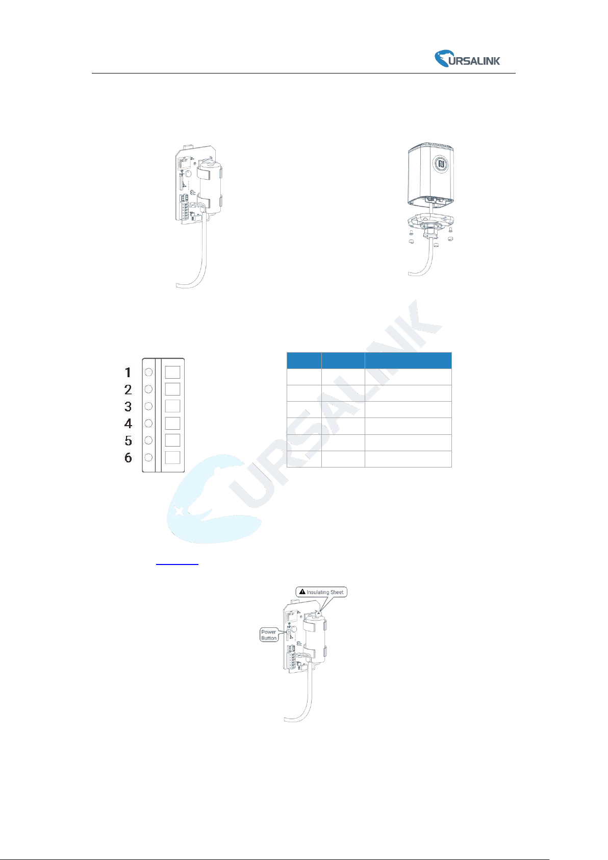
3.1 Sensor Assembly
Follow the steps below to connect pressure sensor cable to EM500 transceiver if they are
separated.
Back View:
④Battery (Internal)
⑤Wall Mounting Holes
⑥Pole Mounting Holes
2. Pass the cable through the cap, rubber seal
and enclosure cover.
1. Take off the mounting bracket, remove the cap,
rubber seal and the screws on the bottom of the
device, and then take off the enclosure cover.
EM500-PP User Guide
7
Pinouts:
3.2 Insulating Sheet Disassembly
Pull out the insulating sheet on the side of the battery and check if electrode of the battery is
reversed.
Note: Refer to Chapter 4 to check if EM500 can be turned on via power button.
PIN
Color
Description
1
Red
GND
2
--
--
3
---
--
4
White
B
5
Yellow
A
6
Black
VOUT
4. Put the motherboard back and restore
everything in its due position.
3. Pull out the motherboard, insert and lock
the wires accordingly (see the label on the
motherboard or following picture).

EM500-PP User Guide
8
4. Turn ON/OFF and Reset (Power Button)
The LED indicator is inside the device. EM500-PP can also be turned on/off and reset
via Mobile APP or Toolbox.
Function
Action
LED Indication
Turn On
Press and hold the button for more than
3 seconds.
Off → Static Green
Turn Off
Press and hold the button for more than
3 seconds.
Static Green -> Off
Reset
Press and hold the button for more than
10 seconds.
Note: EM500 will automatically power on after
reset.
Blink 3 times.
Check On/Off Status
Quickly press the power button.
Light On: Device is on.
Light Off: Device is off.
5. Sensor Configuration
Ursalink EM500-PP sensor can be monitored and configured via one of the following methods:
Mobile APP (NFC);
Windows software (NFC or Type-C port).
In order to protect the security of sensor, password validation is required when turning on/off the
sensor or changing configuration. Default password is 123456.
5.1 Configuration via Smartphone APP
Preparation:
Smartphone (NFC supported)
Toolbox APP: download and install from Google Play or Apple Store.
5.1.1 Read/Write Configuration via NFC
1. Enable NFC on the smartphone and open “Toolbox” APP.
2. Attach the smartphone with NFC area to the device to read basic information.
Note: Ensure your smartphone NFC area and it is recommended to take off phone case before
using NFC.

EM500-PP User Guide
9
3. When you perform one of the following operations, enter the password and attach the
smartphone with NFC area to the device until the APP shows a successful prompt.
Turn on/off the sensor
Reset the sensor
Tap “Write” to change settings in “Device > Settings”.
1. Go to “Device > Status” to tap “Read” and attach the smartphone with NFC area to the device
to read real-time data of sensor.

EM500-PP User Guide
10
5.1.2 Template Configuration
Template settings are used for easy and quick device configuration in bulk.
Note: Template function is allowed only for sensors with the same model and LoRa frequency
band.
1. Go to “Template” page on the APP and save current settings as a template.
2. Attach the smartphone with NFC area to another device.
3. Select the template file from Toolbox APP and tap “Write”.
4. Enter password of this device and keep the two devices close until the APP shows a successful
prompt.
Table of contents
Other Ursalink Accessories manuals

Ursalink
Ursalink AM100 Series User manual

Ursalink
Ursalink EM500-LGT User manual

Ursalink
Ursalink EM500-CO2 User manual

Ursalink
Ursalink EM500-SMT Series User manual

Ursalink
Ursalink EM500-PT100 User manual

Ursalink
Ursalink EM500-UDL User manual

Ursalink
Ursalink EM500-SMT Series User manual

Ursalink
Ursalink EM500-SWL User manual

Ursalink
Ursalink EM500 Series User manual

Ursalink
Ursalink UC11-N1 User manual


