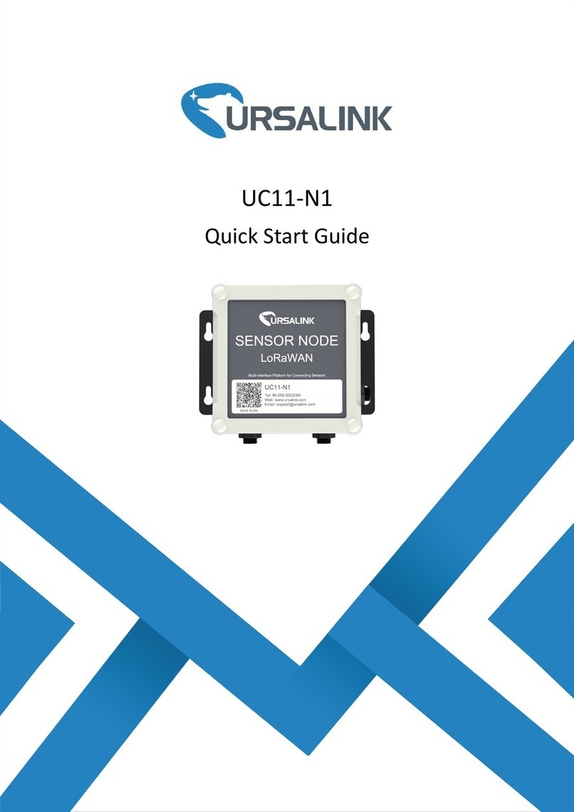
Ursalink UC11-N1 User manual


2
Contents
1. Specification....................................................................................................................................3
2. Introduction.................................................................................................................................... 3
2.1 Features.................................................................................................................................3
2.2 Parameters............................................................................................................................ 4
2.3 Terminal Description............................................................................................................ 5
2.4 Turn on/off the Device......................................................................................................... 5
3. Configuring via PC...........................................................................................................................6
3.1 Configuring via ToolBox........................................................................................................6
3.2 Status.....................................................................................................................................7
3.3 General..................................................................................................................................7
3.3.1 Basic........................................................................................................................... 7
3.3.2 Serial-RS485 (Modbus Master).................................................................................8
3.3.3 Serial-RS232.............................................................................................................11
3.3.4 GPIO......................................................................................................................... 12
3.3.5 Pulse Counter...........................................................................................................13
3.3.6 AI.............................................................................................................................. 15
3.4 LoRaWAN............................................................................................................................ 16
3.4.1 Basic-OTAA...............................................................................................................16
3.4.2 Basic-ABP................................................................................................................. 19
3.4.3 Channel.................................................................................................................... 21
3.5 Upgrade...............................................................................................................................22
4.Configuration via Ursalink Cloud.................................................................................................. 23
4.1 Account Setup.....................................................................................................................23
4.2 Add a Ursalink LoRaWAN Gateway................................................................................... 24
4.3 Add Devices to Ursalink Cloud...........................................................................................25
4.4 Check the Data of UC11-N1................................................................................................28
4.5 Configure UC11-N1 via Ursalink Cloud.............................................................................. 29
4.5.1 Basic Settings........................................................................................................... 29
4.5.2 Interface Settings.....................................................................................................30
5.Configuration via TTN....................................................................................................................32
5.1 Add UC11-N1 to The Things Network................................................................................32
5.1.1 Create an Application in The Things Network....................................................... 32
5.1.2 Add Devices to the Application.............................................................................. 34
5.1.3 Configure UC11-N1..................................................................................................35
5.2 Check Data Transmission on The Things Network............................................................ 36
3
1. Preface
Thank you for choosing Ursalink UC11-N1. This user guide will present in detail all the functions
and features of the product. The UC11-N1 is designed for both industrial and commercial
applications and helps devices stay connected. The product should be used under the guidance
of this user guide, referring to parameters and technical specifications. The UC11-N1 is a compact,
high-performance device that offers LoRaWAN connectivity for remote access and easy
management of machines and equipment over the LoRaWAN gateway.
We bear no liability for property loss or physically injury arising from abnormal or incorrect usage
of this product.
2. Introduction
UC11-N1 is a smart wireless module featuring LoRaWAN protocol. Supporting the most widely
used industrial communication network protocols. UC11-N1 covers industries like industrial
automation, building automation and smart agricultural applications, to provide network
capability in remote or factory floor environments. It can also connect 4-20mA/0-10V analog
devices, the most commonly deployed devices in industrial environments.
This user guide is intended to provide detailed technical specifications and explanations to basic
users as well as the technically-minded groups. It is a live document, and will be updated from
time to time. Please ensure that you have the latest version, by checking our website at:
https://www.ursalink.com/en/documents-download/
Note: Please contact Ursalink or the original battery manufacturer to replace the battery!
2.1 Features
Add or change a device probe in seconds
Multiple interfaces including serial and I/Os
Battery powered and DC powered with solar panel option
Battery life: 5 years life under LoRaWAN Class A mode
Support Frequency: EU433/CN470/EU868/RU864/IN865/US915/AU915/AS923/KR920
Robust waterproof IP67 enclosure
LoRa wireless module included, up to 11km communicate range

4
2.2 Specification
LoRaWAN
Frequency
EU433/CN470/IN865/EU868/RU864/US915/AU915/KR920/AS923
Tx Power
20dBm
Sensitivity
-147dBm @300bps
Mode
OTAA/ABP
Interfaces
Interface Type
M12 A-Coded Male
IO
Ports
2 × GPIO
Logical Level
Low: 0~0.9V, High: 2.5~3.3V
Work Mode
Digital input, Digital output, Pulse Counter (only GPIO2 supported
in N1-DC)
Serial Port
Ports
1 × RS232 or RS485 (Switchable)
Baud Rate (bps)
1200, 2400, 4800, 9600, 57600, 115200
Protocol
Transparent (RS232), Modbus RTU (RS485)
Analog Input
Ports
2 × Analog input
Resolution
12 bit
Input Range
4~20mA or 0~10V (Switchable)
Power Output
Ports
2 × 3.3 V, 2 × 5/9/12 V (Switchable)
Configuration Interface
Ports
1 × USB
Physical Characteristics
Operating Temperature
-20°C to +70°C
Ingress Protection
IP67
Dimension
120.1 × 120.1× 55.4 mm (4.73 × 4.73 × 2.18 in)
Power Input
1. 19000mAh replaceable Li-SOCL2 battery

5
2. 5-24 VDC with 4900mAh battery backup
Power Connector
(DC version)
M12 A-Coded 4-pin Male
2.3 Terminal Description
2.4 Turn on/off the Device
Put a magnet close to the reed switch to turn on or turn off the device.
Buzzer rings for 2 seconds: power on.
Buzzer rings for 6 seconds: power off.

6
3. Configuring via PC
3.1 Configuring via ToolBox
Follow these steps:
Step 1: Connect the Ursalink UC11-N1 to PC via USB port.
Step 2: Power on the Ursalink UC11-N1.
Step 3: Run the Ursalink ToolBox.
Serial Port Settings
Item
Description
Default
Serial Port
Select the serial port for data transmission.
Null
Login Password
Enter the correct password to login.
123456
Baud Rate
Select from "9600", "57600", "115200".
57600
Data Bit
Select from "5", "7", "8".
8
Parity Bit
Select from "Even", "Odd", "None".
None
Stop Bit
Select from "1", "2".
1
If the serial port parameter is correct, it will display: Serial port is connected.

7
3.2 Status
Click "Status" to see the basic status information of this device:
3.3 General
3.3.1 Basic

8
Basic Settings
Item
Description
Default
Device ID
Show the Serial Number of this device.
The
identifier
of this
device.
Description
Enter the description of this device.
Null
Reporting
Interval
The UC11-N1 reports the collected data at regular
intervals.
Range: 30-86400 (s)
1200
Interface 1
(Pin2) 3V3
Output
Enabled: UC11-N1 will provide power to device
connected to Interface 1 (pin2). Voltage is 3.3V.
Disabled
Interface 2
(Pin2) 3V3
Output
Enabled: UC11-N1 will provide power to device
connected to Interface 2 (pin2). Voltage is 3.3V
Disabled
Change
Password
Enable: Change Toolbox login password.
Disabled
3.3.2 Serial-RS485 (Modbus Master)
On this page, you can enable the serial ports and set the parameters of RS485 (Modbus
Master).

9
RS485 Settings
Item
Description
Default
Enable
Enable/Disable serial interface
Enable
Interface Type
Set the interface type.
Select from RS485 (Modbus Master) and
RS232.
RS485
(Modbus
Master)
Interface 1 (Pin 1)
5/9/12V Output
Enable: UC11-N1 will provide power to
the device connected to Interface 1
(Pin 1). Voltage is 5V, 9V or 12V.
Disabled
Power Output
Time Before
Collect
If the time is set 100ms, then before
collecting data from end nodes,
UC11-N1 will provide power for the end
node for 100ms.
Range: 1-5000 (ms).
Note: With this feature being enabled,
the power consumption will increase.
None
Baud Rate
Select from "1200", "2400", "4800",
"9600", "57600" and "115200".
9600
Data Bits
Select from "5", "7", "8".
8
Stop Bits
Select from "1", "2".
1
Parity Bits
Select from "Even", "Odd", "None".
None
Data Polling
Interval
Set the interval for reading remote
channels. When the reading cycle ends,
the new reading cycle begins until this
interval over. If it is set to 0, the device
will restart the new reading cycle after
all channels have been read.
Range: 0-86400 (s).
0
Execution Interval
(ms)
The execution interval between each
command. Range: 10-1000.
50
Max Resp Time
(ms)
Set the maximum response time that
the UC11-N1 waits for the response to
the command. If the device does not get
a response after the maximum response
time, it is determined that the
command has timed out. Range:
10-1000.
500
Max Retry Times
Set the maximum retry times after it
3

10
fails to read, range: 0-5.
Modbus RS485
bridge LoRaWAN
Enable this mode to collect data from
slave devices and then send them to
Network Server via LoRaWAN.
This mode also has the capability to
change the behaviour of the ModBus
device by writing into its registers.
Disable
Port
Enter the LoRaWAN frame port for
transparent transmission between
UC11-N1 and Network Server.
Range: 2-84, 86-223.
Null
Channel Settings
Item
Description
Default
Channel ID
Assign the channel for the slave device,
8 channels selectable.
Null
Name
Set the name to identify the remote
channel. It cannot be blank.
Null
Slave ID
Set Modbus slave ID.
Null
Address
The starting address for reading.
Null
Quantity
Set read how many digits from starting
address.
Null
Type
Read command, options are "Coil",
"Discrete", "Holding Register (INT16)",
"Input Register (INT16)", "Holding
Register (INT32)" and "Holding Register
(Float)".
Holding
Register
(INT16)

11
You could click to add a channel or click to delete a channel.
3.3.3 Serial-RS232
Sign
Identify whether this channel is signed.
Default: Unsigned.
Null
Value
Show the data which read from this
slave device.
Null
Fetch
Click to read the data from this slave
device.
Null
RS232 Settings
Item
Description
Default
Enable
Enable/Disable serial interface
Enable
Interface Type
Set the interface type.
Select from RS485 (Modbus Master) and
RS232.
RS485
(Modbus
Master)
Interface 1 (Pin 1)
5v/9v/12v Output
Enable: UC11-N1 will provide power to
the device that connected to Interface
Disabled

12
3.3.4 GPIO
1 (Pin 1). Voltage is 5V, 9V or 12V.
Note: Power supply function only
available on DC powered version.
Power Output
Time Before
Collect
If the time is set 100ms, then before
collecting data from end nodes,
UC11-N1 will provide power for end
nodes for 100ms.
Range: 1-5000 (ms).
Note: With this feature being enabled,
the power consumption will increase.
None
Baud Rate
Select from "1200", "2400",
"4800","9600", "57600", "115200".
9600
Data Bits
Select from "5", "7", "8".
8
Stop Bits
Select from "1", "2".
1
Parity Bits
Select from "Even", "Odd", "None".
None

13
3.3.5 Pulse Counter
Note: The Pulse Counter feature is only available on GPIO 2 of UC11-N1 DC powered version.
GPIO Settings
Item
Description
Default
Interface Name
Show the name of this interface.
Null
Enable
Click to enable this interface.
Disable
Interface Type
Choose from: Digital Input,Digital
Output
Digital Input: This GPIO will be used as
Digital Input. Then you will need to
select the initial state of this digital input
from “Pull Up” (High), “Pull Down”
(Low).
Digital Output: This GPIO will be used as
Digital Output.
Digital Input
Status
Show the current status of this interface.
Click “Fetch” to fetch the latest status.
Null

14
GPIO 2 Settings
Item
Description
Default
Interface Name
Show the name of this interface.
Null
Enable
Click to enable this interface.
Disable
Interface Type
Choose from: Digital Input,Digital
Output
Digital Input: This GPIO will be used as
Digital Input. Then you will need to
select the initial state of this digital input
form “Pull Up”(High), “Pull Down”(Low).
Digital Output: This GPIO will be used as
Digital Output.
Counter: This GPIO will be used as the
pulse counter.
Digital Input2
Keep Last Value
when Power Off
Enable: The device will store the last
counter value in the register
when the module is powered off.
Disable
Counter Value
It will continuously show the present
counter value unless it stops.
Null
Refresh
Click to refresh the counter value.
Null
Stop/Start
Click the Star/Stop button to start or
stop the counter.
Null
Reset
Click the Clear button to reset the
counter value.
Null

15
3.3.6 AI
Note: Please adjust the ADC sampling DIP switch on PCB to the corresponding mode before chan
ging the type of analog input signal.
AI Settings
Item
Description
Default
Interface 2 (Pin 1)
5/9/12V Output
Enable: UC11-N1 will provide power to
device connected to Interface 1 (pin1).
Voltage is 5V, 9V or 12V.
Disabled
Power Output
Time Before
Collect
If the time is set to 100ms, then before
collecting data from end nodes,
UC11-N1 will provider power for end
nodes for 100ms.
Range: 1-5000 (ms).
1-5000

16
3.4 LoRaWAN
3.4.1 Basic-OTAA
Note: With this feature being enabled,
the power consumption will increase.
Data Polling
Interval
Set the interval for reading analog input.
Range: 5-3600 (s).
5
Interface Name
Show the name of this interface.
Null
Enable
Click to enable this interface.
Disable
Analog Input
Signal Type
Select from: “4-20 mA”, “0-10 V”.
4-20 mA
Status
Show the current value of this interface.
Click “Fetch” to fetch the latest value of
this analog input.
Null

17
Basic Settings-OTAA
Item
Description
Default
Device EUI
Show the identifier of this device.
the
identifier
of this
device.
App EUI
Enter the application EUI.The Network Server receives
request and consults the entity associated with the APP
EUI to validate the request.If permission is granted, it
responds with a join-accept message.
24E124C00
02A0001
Application Port
The port used by the device to send and receive
LoRaWAN data.
85
RS232 Port
The port used by the device to send and receive RS232
data.
86
Working Mode
Show the working mode of the device.
UC11-N1: Null.
UC11-N1-DC: “Class A” , “Class C”.
Class A :Class A operation is the lowest power
end-device system.
Class C: Class C end-device will use more power to
operate than Class A but they offer the lowest latency
for server to end-device communication.
Class A
Join Type
Select from: "OTAA" and "ABP".
OTAA:Over-the-Air Activation.
For over-the-air activation, end-devices must follow a
join procedure prior to participating in data exchanges
with the network server. An end-device has to go
through a new join procedure every time it has lost the
session context information.
OTAA

18
ABP: Activation by Personalization.
Under certain circumstances, end-devices can be
activated by personalization. Activation by
personalization directly ties an end-device to a specific
network by-passing the join request - join accept
procedure.
Application Key
Enter the application key. Whenever an end-device joins
a network via over-the-air activation, the application key
is used to derive the Application Session key.
5572404c6
96e6b4c6f
526132303
13823
Regular Report
Confirmed
After sending the regular report packet to the network
server, if the device does not receive ACK bit from the
network server, then the device will resend the packet.
Note: If the device doesn't receive ACK for a long time,
the device will resend regular report confirmed packets
3 times at most.
Disabled
Alarm Report
Confirmed
After sending the attribute package or alarm packet or
battery packet to the network server, if the device does
not receive ACK bit from the Network Server, then the
device will resend the packet.
Note: If you doesn't receive ACK for a long time, the
device will resend alarm report packets or battery
packets 3 times at most. However, the device will resend
attribute package all the time.
Disabled

19
3.4.2 Basic-ABP
Basic Settings-ABP
Item
Description
Default
Device EUI
Show the identifier of this device.
the
identifier
of this
device.
App EUI
Enter the application EUI.The Network Server receives
request and consults the entity associated with the
APPEUI to validate the request.If permission is granted, it
responds with a join-accept message.
24E124C00
02A0001
Application Port
The port used by the device to send and receive
LoRaWAN data.
85
RS232 Port
The port used by the device to send and receive RS232
data.
86
Working Mode
Show the working mode of the device.
Class A

20
UC11-N1: Null.
UC11-N1-DC: Select from: “Class A” , “Class C”.
Class A :Class A operation is the lowest power
end-device system.
Class C: Class C end-device will use more power to
operate than Class A but they offer the lowest latency
for server to end-device communication.
Join Type
Select from: "OTAA" and "ABP".
OTAA:Over-the-Air Activation.
For over-the-air activation, end-devices must follow a
join procedure prior to participating in data exchanges
with the network server. An end-device has to go
through a new join procedure every time it has lost the
session context information.
ABP: Activation by Personalization.
Under certain circumstances, end-devices can be
activated by personalization. Activation by
personalization directly ties an end-device to a specific
network by-passing the join request - join accept
procedure.
OTAA
Device Address
Enter the device address. The device address identifies
the end-device within the current network.
The last 8
digits
number of
SN
Network Session
Key
Enter the network session key of the device. The
network session key specific for the end-device. It is used
by the end-device to calculate the MIC or part of the MIC
(message integrity code) of all uplink data messages to
ensure data integrity.
5572404c6
96e6b4c6f
526132303
13823
Application
Session Key
Enter the application session key of the device. The
AppKey is an application session key specific for the
end-device. It is used by both the application server and
the end-device to encrypt and decrypt the payload field
of application-specific data messages.
5572404c6
96e6b4c6f
526132303
13823
Regular Report
Confirmed
After sending the regular report packet to the network
server, if the device does not receive ACK bit from the
network server, then the device will resend the packet.
Note: If the device doesn't receive ACK for a long time,
the device will resend regular report confirmed packets
Disabled
Other manuals for UC11-N1
3
Table of contents
Other Ursalink Accessories manuals

Ursalink
Ursalink EM500-SMT Series User manual

Ursalink
Ursalink EM500-SWL User manual

Ursalink
Ursalink EM500 Series User manual

Ursalink
Ursalink EM500-UDL User manual

Ursalink
Ursalink AM100 Series User manual

Ursalink
Ursalink EM500 Series User manual

Ursalink
Ursalink UC11-N1 User manual

Ursalink
Ursalink EM500-PT100 User manual

Ursalink
Ursalink AM100 Series User manual

Ursalink
Ursalink EM500-SMT Series User manual