Ursalink EM500-SMT Series User manual


EM500-SMT User Guide
2
Safety Precautions
Ursalink will not shoulder responsibility for any loss or damage resulting from not following
the instructions of this operating guide.
The device must not be remodeled in any way.
Please clarify your application environment before deployment, in case the device can
function well.
The device is not intended to be used as a reference sensor, and Ursalink will not should
responsibility for any damage which may result from inaccurate readings.
Do not place the device cable close to objects with naked flames.
Do not place the device, cable and sensor where the temperature is below/above the
operating range.
Make sure electronic components do not drop out of the enclosure while opening.
When closing the lid, make sure the lid is fitted the right way, so that the enclosure is
properly sealed.
When installing the battery, please install it accurately, and do not install the reverse or
wrong model.
The device must never be subjected to shocks or impacts.
Declaration of Conformity
Ursalink EM500-SMT is in conformity with the essential requirements and other relevant
provisions of the CE, FCC, and RoHS.
© 2017-2020 Xiamen Ursalink Technology Co., Ltd.
All rights reserved.
All information in this guide is protected by copyright law. Whereby, no organization or individual
shall copy or reproduce the whole or part of this user guide by any means without written
authorization from Xiamen Ursalink Technology Co., Ltd.
For assistance, please contact
Ursalink technical support:
Email: helpdesk@ursalink.com
Tel: 86-592-5023060
Fax: 86-592-5023065
Revision History
Date
Doc Version
Description
April 7, 2020
V 1.0
Initial version
August 17, 2020
V 1.1
Document structure change

EM500-SMT User Guide
3
Contents
1. Overview..........................................................................................................................................4
1.1 Description............................................................................................................................ 4
1.2 Features................................................................................................................................. 4
1.3 Specifications.........................................................................................................................4
2. Hardware Introduction.................................................................................................................... 5
2.1 Packing List............................................................................................................................ 5
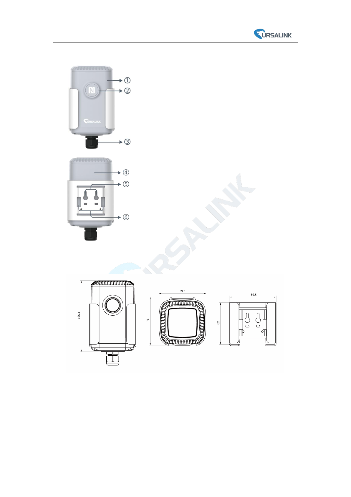
2.2 Transceiver Overview............................................................................................................ 6
2.3 Dimensions............................................................................................................................ 6
3. Assembly and Preparation.............................................................................................................. 6
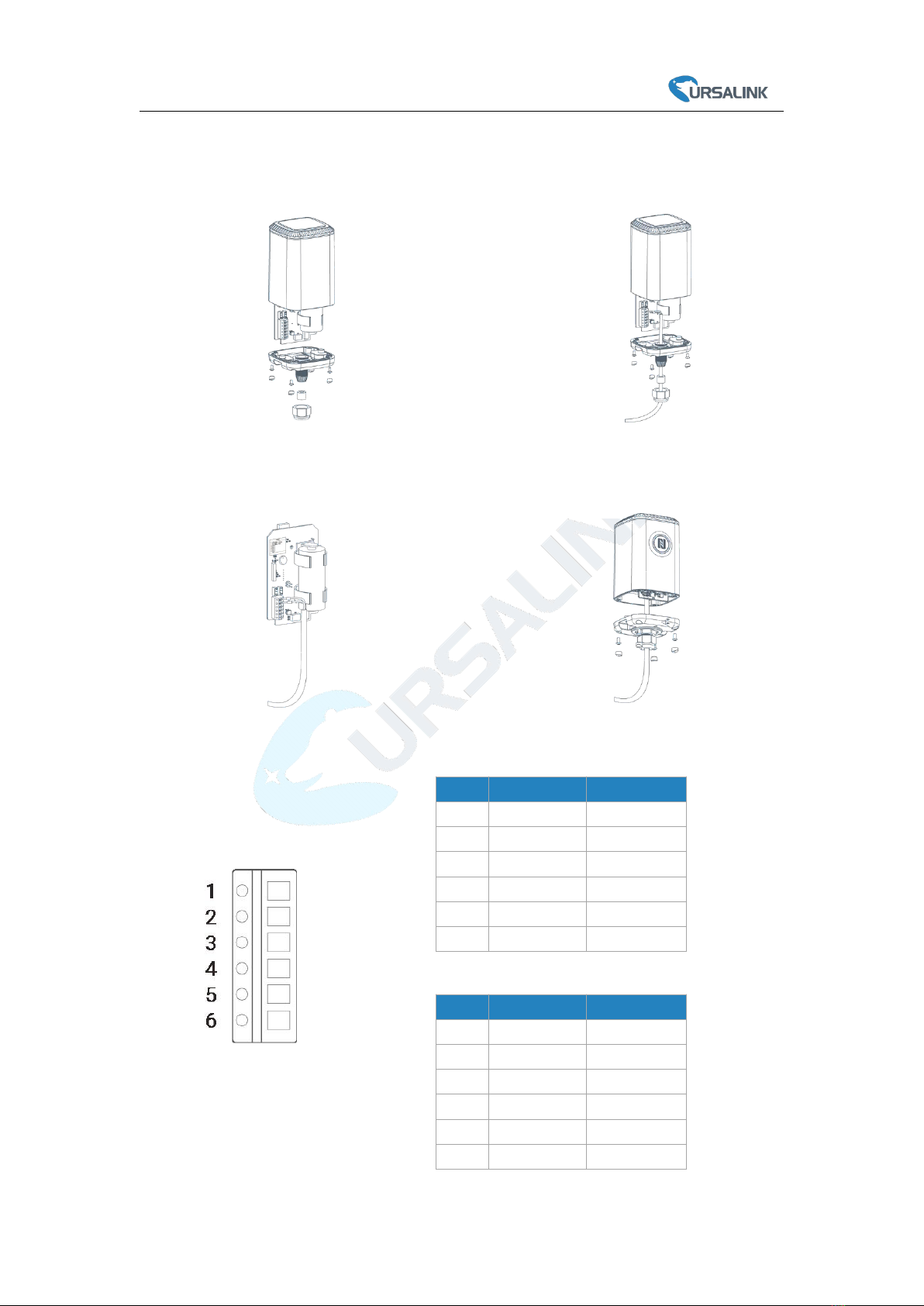
3.1 Sensor Assembly................................................................................................................... 6
3.2 Insulating Sheet Disassembly................................................................................................8
4. Turn ON/OFF and Reset (Power Button).........................................................................................8
5. Sensor Configuration....................................................................................................................... 8
5.1 Configuration via Smartphone APP.......................................................................................9
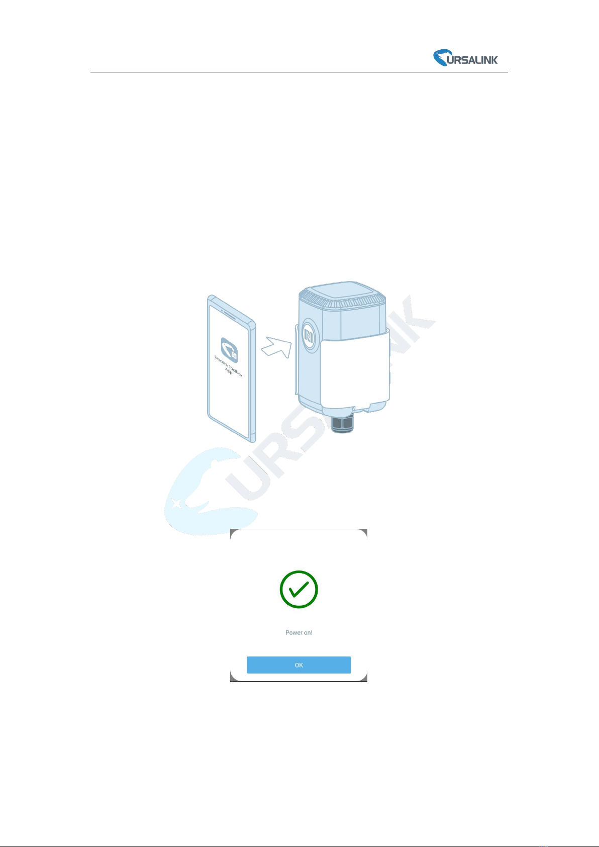
5.1.1 Read/Write Configuration via NFC.............................................................................9
5.1.2 Template Configuration............................................................................................10
5.2 Configuration via PC............................................................................................................ 11
5.2.1 Log in the Toolbox.................................................................................................... 12
5.2.2 Basic Configuration.................................................................................................. 13
5.2.3 Template and Reset..................................................................................................14
5.2.4 Upgrade.................................................................................................................... 14
5.3 Configuration Examples...................................................................................................... 15
5.3.1 LoRaWAN Channel Settings..................................................................................... 15
5.3.2 Data Calibration Settings..........................................................................................16
5.3.3 Alarm Settings.......................................................................................................... 16
6. Installation..................................................................................................................................... 17
6.1 Transceiver Installation....................................................................................................... 17
6.1.1 Wall Mounting..........................................................................................................17
6.1.2 Pole Mounting..........................................................................................................18
6.1.3 DIN Rail Mounting.................................................................................................... 18
6.2 Sensor Installation...............................................................................................................18
6.2.1 Horizontal Installation.............................................................................................. 19
6.2.2 Vertical Installation.................................................................................................. 19
7. Payload Format..............................................................................................................................20
8.Sensor Management via Ursalink Cloud........................................................................................ 21
8.1 Ursalink Cloud Registration................................................................................................. 21
8.2 Add a Ursalink LoRaWAN Gateway..................................................................................... 21
8.3 Add EM500-SMT to Cloud...................................................................................................23
Appendix............................................................................................................................................23
Default LoRaWAN Parameters.................................................................................................. 24
Default Uplink Channels............................................................................................................24

EM500-SMT User Guide
4
1. Overview
1.1 Description
EM500-SMT is an outdoor environment monitoring sensor mainly used to measure soil status
through wireless LoRa network. EM500-SMT device is battery powered and designed for multiple
mounting ways. It is equipped with NFC (Near Field Communication) and can easily be configured
by a smartphone or a PC software.
Sensor data are transmitted in real-time using standard LoRaWAN protocol. LoRaWAN enables
encrypted radio transmissions over long distance while consuming very little power.
The user can obtain sensor data and view the trend of data change through Ursalink Cloud or thr
ough the user's own Network Server.
1.2 Features
A portable, robust and waterproof solution for smart agricultural applications
Up to 11km communication range
Easy configuration via NFC
Standard LoRaWAN support
Ursalink Cloud compliant
Low power consumption with 19000mAh replaceable battery
1.3 Specifications
Model
EM500-SMT-EC5
EM500-SMT-MEC20
Measurement
Moisture
Range
0-100% RH
Accuracy
±2%
±2%(0~50%),
±3%(50%~100%)
Resolution
0.5%
0.03%(0~50%),
1%(50%~100%)
Temperature
Range
—
-40°C ~80°C
Accuracy
—
±0.5°C
Resolution
—
0.1°C
Electrical Conductivity
Range
—
0~20000 µs/cm

EM500-SMT User Guide
5
Accuracy
—
±3%(0~10000 µs/cm),
±5%(10000~20000 µs/cm)
Resolution
—
10µs/cm(0~10000 µs/cm)
50µs/cm(10000~20000 µs/cm)
LoRaWAN
Frequency
EU433/CN470/IN865/RU864/EU868/US915/AU915/KR920/AS923
Tx Power
20dBm
Sensitivity
-147dBm @300bps
Mode
OTAA/ABP Class A
Antenna
Embedded Ceramic Antenna
Physical Characteristics
Cable Length
5m(EC5), 2m(MEC20)
Power Supply
19000 mAh Li-SoCl2battery
Operating Temperature
-30°C to +60°C(EC5)
-30°C to +70°C(MEC20)
Relative Humidity
0% to 100% (non-condensing)
Mounting
Pole, wall, DIN rail
2. Hardware Introduction
2.1 Packing List
1 × EM500-SMT
(Include sensor)
2 × Mounting
Screws
1 × Hose
Clamp
1 × Warranty Card
1 × Quick Guide
1 × DIN Rail (Optional)
If any of the above items is missing or damaged, please contact your Ursalink sales
representative.

EM500-SMT User Guide
6
2.2 Transceiver Overview
2.3 Dimensions(mm)
3. Assembly and Preparation
3.1 Sensor Assembly
Follow the steps below to connect light sensor cable to EM500 transceiver if they are
separated.
Front View:
①LoRa Antenna (Internal)
②NFC Area
③Water-proof Connector
Back View:
④Battery (Internal)
⑤Wall Mounting Holes
⑥Pole Mounting Holes

EM500-SMT User Guide
7
Pinouts:
EM500-SMT-EC5:
EM500-SMT-MEC20:
PIN
Color
Description
1
Bare wire
GND
2
Yellow
AIN
3
---
--
4
--
--
5
--
--
6
Brown
VOUT=12V
PIN
Color
Description
1
Black
GND
2
---
--
3
---
--
4
White
B
5
Yellow
A
6
Red
VOUT=12V
4. Put the motherboard back and restore
everything in its due position.
3. Pull out the motherboard, insert and lock
the wires accordingly (see the label on the
motherboard or following picture).
2. Pass the cable through the cap, rubber seal
and enclosure cover.
1. Take off the mounting bracket, remove the cap,
rubber seal and the screws on the bottom of the
device, and then take off the enclosure cover.

EM500-SMT User Guide
8
3.2 Insulating Sheet Disassembly
Pull out the insulating sheet on the side of the battery and check if electrode of the battery is
reversed.
Note: Refer to Chapter 4 to check if EM500 can be turned on via power button.
4. Turn ON/OFF and Reset (Power Button)
The LED indicator is inside the device. EM500-SMT can also be turned on/off and
reset via Mobile APP or Toolbox.
Function
Action
LED Indication
Turn On
Press and hold the button for more than
3 seconds.
Off → Static Green
Turn Off
Press and hold the button for more than
3 seconds.
Static Green -> Off
Reset
Press and hold the button for more than
10 seconds.
Note: EM500 will automatically power on after
reset.
Blink 3 times.
Check On/Off Status
Quickly press the power button.
Light On: Device is on.
Light Off: Device is off.
5. Sensor Configuration
Ursalink EM500-SMT sensor can be monitored and configured via one of the following methods:
Mobile APP (NFC);
Windows software (NFC or Type-C port).
In order to protect the security of sensor, password validation is required when turning on/off the
sensor or changing configuration. Default password is 123456.

EM500-SMT User Guide
9
5.1 Configuration via Smartphone APP
Preparation:
Smartphone (NFC supported)
Toolbox APP: download and install from Google Play or Apple Store.
5.1.1 Read/Write Configuration via NFC
1. Enable NFC on the smartphone and open “Toolbox” APP.
2. Attach the smartphone with NFC area to the device to read basic information.
Note: Ensure your smartphone NFC area and it is recommended to take off phone case before
using NFC.
3. When you perform one of the following operations, enter the password and attach the
smartphone with NFC area to the device until the APP shows a successful prompt.
Turn on/off the sensor
Reset the sensor
Tap “Write” to change settings in “Device > Settings”.
4. Go to “Device > Status” to tap “Read” and attach the smartphone with NFC area to the device
to read real-time data of sensor.

EM500-SMT User Guide
10
5.1.2 Template Configuration
Template settings are used for easy and quick device configuration in bulk.
Note: Template function is allowed only for sensors with the same model and LoRa frequency
band.
1. Go to “Template” page on the APP and save current settings as a template.
2. Attach the smartphone with NFC area to another device.
3. Select the template file from Toolbox APP and tap “Write”.

EM500-SMT User Guide
11
4. Enter password of this device and keep the two devices close until the APP shows a successful
prompt.
5. Slide the template item to the left to edit or delete the template.
5.2 Configuration via PC
Preparation:
Dedicated NFC Reader or Type-C USB cable
PC (Windows 10)
Toolbox: https://www.ursalink.com/en/software-download/

EM500-SMT User Guide
12
5.2.1 Log in the Toolbox
Make sure “Toolbox” is downloaded on your computer. Select one of the following methods to
log in Toolbox.
Type-C Connection
1. Connect the EM500-SMT to computer via type-C port.
Type-C port is inside the transceiver of the EM500-SMT.
2. Select type as “General” and click password to log in Toolbox. (Default password: 123456)
NFC Connection
1. Connect the NFC reader to computer, then attach the EM500-SMT to NFC area of the reader.
2. Select type as “NFC” and serial port as NFC reader port on Toolbox.

EM500-SMT User Guide
13
5.2.2 Basic Configuration
1. Click “Read” to read current data of the sensor.
2. When you perform one of the following operations, enter the password and wait a few
seconds until toolbox shows a successful prompt. (Password is not needed if you connect it via
type-C port)
Turn on/off the sensor
Reset the sensor
Click “Write” to change settings

EM500-SMT User Guide
14
5.2.3 Template and Reset
5.2.3.1 Template Configuration
Note: Template function is allowed only for sensors with the same model and LoRa frequency
band.
1. Go to “Maintenance -> Template and Reset” page in Toolbox.
2. Click “Export” to save the current settings as a template.
3. Click “Browse” to select the correct template from computer.
4. Click “Import” to import the template to the device.
5.2.4.2 Reset
Go to “Maintenance -> Template and Reset” page in Toolbox, then click the “Reset” to reset the
device to the factory settings.
5.2.4 Upgrade
1. Download firmware on your computer.
2. Go to “Maintenance -> Upgrade” page in Toolbox.
3. Click “Browse” and select the firmware from computer.
4. Click “Upgrade” to upgrade the device.
Note: If NFC connection is selected, please keep the two devices close and don’t move them in
order to get the best connectivity as possible when upgrading.

EM500-SMT User Guide
15
5.3 Configuration Examples
5.3.1 LoRaWAN Channel Settings
The configuration of LoRaWAN channel of EM500-SMT must match the LoRaWAN gateway’s.
Refer to Appendix to check default channel settings of EM500-SMT.
Mobile APP Configuration:
Open Toolbox APP and go to “Device ->Setting -> LoRaWAN Settings”to change the frequency and
channels.
Software Configuration:
Log in Toolbox and go to “LoRaWAN Settings -> Channel” to change frequency and channels.
Note: If frequency is one of CN470/AU915/US915, you can enter the index of the channel that
you want to enable in the input box, making them separated by commas.
Examples:
1, 40: Enabling Channel 1 and Channel 40
1-40: Enabling Channel 1 to Channel 40
1-40, 60: Enabling Channel 1 to Channel 40 and Channel 60
All: Enabling all channels
Null: Indicates that all channels are disabled

EM500-SMT User Guide
16
5.3.2 Data Calibration Settings
Mobile APP Configuration:
Open Toolbox APP and go to “Device -> Setting -> Calibration Settings”to enable the calibration
and input the calibration value.
Software Configuration:
Log in Toolbox and go to “Device Settings -> Basic -> Calibration Settings” to enable the
calibration and type the calibration value.
5.3.3 Alarm Settings
EM500-SMT will upload the current data instantly after the threshold is triggered.
Mobile APP Configuration:
Open Toolbox APP and go to “Device -> Setting -> Threshold Settings”to enable the threshold
settings and input the threshold.

EM500-SMT User Guide
17
Software Configuration:
Log in Toolbox and go to “Device Settings -> Basic -> Threshold Settings” to enable the calibration
and input the calibration value.
6. Installation
6.1 Transceiver Installation
6.1.1 Wall Mounting
1. Attach the mounting bracket to the wall and mark the two holes(around 16mm) on the wall.
Note: The connecting line of two holes must be a horizontal line.
2. Drill the holes according to the marks and screw the mounting screws into the wall.
3. Mount the device on the wall.

EM500-SMT User Guide
18
6.1.2 Pole Mounting
1.Loosen the hose clamp by turning the locking mechanism counter-clockwise.
1. Straighten out the hose clamp and slide it through the rectangular holes in the mounting
bracket, wrap the hose clamp around the pole.
2. Use a screwdriver to tighten the locking mechanism by turning it clockwise.
6.1.3 DIN Rail Mounting
Use 2 pieces of M3 × 6 flat head Phillips screws to fix the DIN rail to the device, and then hang
the DIN rail on the mounting bracket. It is necessary to choose a standard bracket.
6.2 Sensor Installation
EM500-SMT should be considered following notes to insure proper installation:
Abnormal data may show up if sensor prongs are exposed in the air.
It is possible to get sticks, bark, roots or other material stuck between the sensor prongs,
which will severely affect the sensor data readings. Any air gaps or excessive soil compaction
around the sensor can also influence the readings.
Do not install the sensor adjacent to large metal objects.
Be careful when inserting the sensor into dense soil, as the prongs will break if excessive
sideways force is used.

EM500-SMT User Guide
19
When installing the sensor in a lightning prone area, please check your lightning protection.
When removing the sensor from the soil, do not pull it out of the soil by the cable. Doing so
may break internal connections and make the sensor unusable.
6.2.1 Horizontal Installation
1. Excavate a hole or trench a few centimeters deeper than the depth at which the sensor is to
be installed.
2. At the installation depth, shave off some soil from the vertical soil surface exposing
undisturbed soil.
3. Insert the sensor into the undisturbed soil surface until the entire sensor is inserted. The tip of
each prong has been sharpened to make it easier to push the sensor into the soil. Be careful with
the sharp tips!
Note: If there is difficulty inserting the sensor, loosen or wet the soil.
4. Backfill the trench taking care to pack the soil back to natural bulk density around the sensor
body.
6.2.2 Vertical Installation
1. Drill a hole to the depth at which the sensor is to be installed.
2. Insert the sensor into the undisturbed soil at the bottom of the drilled hole using a hand or any
other implement that will guide the sensor into the soil at the bottom of the hole.
3. After inserting the sensor, backfill the hole, and take care to pack the soil back to natural bulk
density while not damaging the overmolding of the sensor and the sensor cable in the process.

EM500-SMT User Guide
20
7. Payload Format
All data are based on following format:
Channel1
Type1
Data1
Channel2
Type2
Data2
Channel 3
...
1 Byte
1 Byte
N Bytes
1 Byte
1 Byte
M Bytes
1 Byte
...
Please refer to decoder example: https://github.com/Ursalink-CN/ursalink-decoder
Uplink Packet(HEX)
Channel
Type
Data Example
Unit
01
75(Battery Level)
64 => 100
%
03
67(Temperature)
1901 => 01 19 => 281
Hum=281*0.1=28.1
°C
04
68 (Moisture)
73 => 115
Moisture=115*0.5=57.5
%RH
05
7F(Electrical Conductivity)
F0 00 => 00 F0 =240
µs/cm
FF
01(Ursalink Protocol
Version)
01=> V1.0
/
09 (Hardware Version)
01 40=> V1.4
0a(Software Version)
01 14=> V1.14
0b(Power on Notification)
ff
0c (Power off Notification)
ff
0f(Device Type)
00 => Class A
16 (Device SN)
64 10 90 82 43 75 00 01
=>Device SN is 6410908243750001
Other manuals for EM500-SMT Series
1
This manual suits for next models
2
Table of contents
Other Ursalink Accessories manuals

Ursalink
Ursalink EM500-SMT Series User manual

Ursalink
Ursalink EM500-CO2 User manual

Ursalink
Ursalink EM500-UDL User manual

Ursalink
Ursalink EM500 Series User manual

Ursalink
Ursalink AM100 Series User manual

Ursalink
Ursalink EM500-UDL User manual

Ursalink
Ursalink EM500-SWL User manual

Ursalink
Ursalink EM500-PT100 User manual

Ursalink
Ursalink UC11-T1 User manual

Ursalink
Ursalink AM100 Series User manual