Ursalink EM500-SMT Series User manual


EM500-SMT User Guide
2
Safety Precautions
Ursalink will not shoulder responsibility for any loss or damage resulting from not following
the instructions of this operating guide.
The device must not be remodeled in any way.
Please clarify your application environment before deployment so that the device can
function well.
The device is not intended to be used as a reference sensor, and Ursalink will not should
responsibility for any damage which may result from inaccurate readings.
Do not place the device close to objects with naked flames.
Do not place the device where the temperature is below/above the operating range.
Make sure electronic components do not drop out of the enclosure while opening.
When closing the lid, make sure the lid is fitted the right way, so that the enclosure is
properly sealed.
When installing the battery, please install it accurately, not reversely or with wrong
model.
The device must never be subjected to shocks or impacts.
Declaration of Conformity
Ursalink EM500-SMT is in conformity with the essential requirements and other relevant
provisions of the CE, FCC, and RoHS.
© 2017-2020 Xiamen Ursalink Technology Co., Ltd.
All rights reserved.
All information in this guide is protected by copyright law. Whereby, no organization or individual
shall copy or reproduce the whole or part of this user guide by any means without written
authorization from Xiamen Ursalink Technology Co., Ltd.
For assistance, please contact
Ursalink technical support:
Email: helpdesk@ursalink.com
Tel: 86-592-5023060
Fax: 86-592-5023065
Revision History
Date
Doc Version
Description
April 7, 2020
V 1.0
Initial version

EM500-SMT User Guide
3
Contents
1. Overview..........................................................................................................................................5
1.1 Description............................................................................................................................ 5
1.2 Features................................................................................................................................. 5
1.3 Specifications.........................................................................................................................5
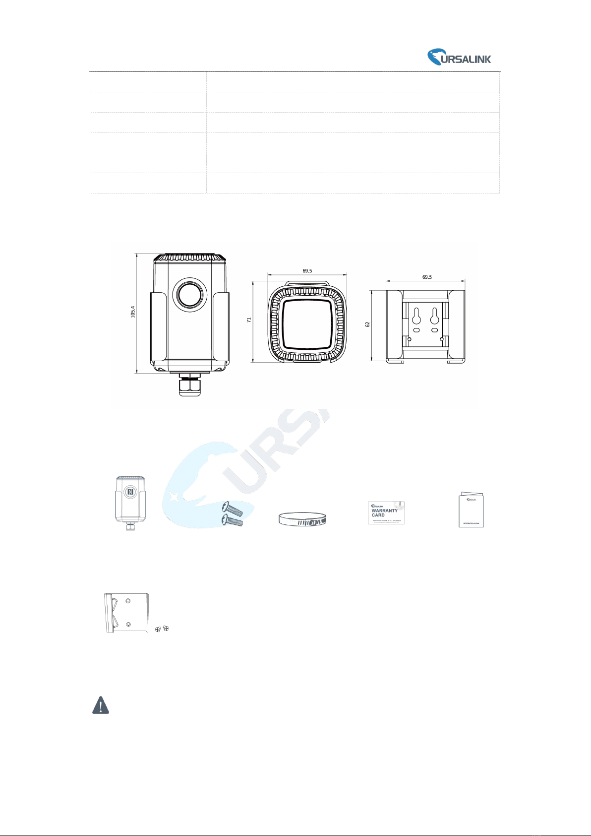
1.4 Dimensions(mm)................................................................................................................... 6
2. Hardware Introduction.................................................................................................................... 6
2.1 Packing List............................................................................................................................ 6
2.2 Product Overview..................................................................................................................7
3. Sensor Connection with EM500......................................................................................................7
4. Sensor Installation........................................................................................................................... 8
4.1 Soil Sensor Installation.......................................................................................................... 8
4.1.1 Horizontal Installation................................................................................................ 8
4.1.2 Vertical Installation.....................................................................................................9
4.2 EM500 Installation.............................................................................................................. 10
4.2.1 Wall Mounting..........................................................................................................10
4.2.2 Pole Mounting..........................................................................................................10
4.2.3 DIN Rail Mounting.................................................................................................... 10
5.Turn ON/OFF the Sensor................................................................................................................ 11
5.1 Turn ON/OFF via Smartphone APP..................................................................................... 11
5.2 Turn ON/OFF via PC Software............................................................................................. 12
5.3 Turn ON/OFF via Button......................................................................................................14
6.Sensor configuration...................................................................................................................... 14
6.1 Configuration via Smartphone APP.....................................................................................14
6.1.1 Read Configuration.................................................................................................. 14
6.1.2 Write Configuration..................................................................................................15
6.1.3 Template Settings..................................................................................................... 16
6.2 Configuration via PC............................................................................................................ 18
6.2.1 Read Configuration.................................................................................................. 18
6.2.2 Write Configuration..................................................................................................18
6.2.3 Upgrade.................................................................................................................... 19
6.2.4 Template and Reset..................................................................................................20
7.Sensor Parameters (for App and PC)..............................................................................................22
7.1 LoRa WAN Settings.............................................................................................................. 22
7.1.1 Basic Settings-OTAA..................................................................................................22
7.1.2 Basic Settings-ABP....................................................................................................23
7.1.3 Channel Settings.......................................................................................................24
7.2 Device Settings.................................................................................................................... 26
7.2.1 General..................................................................................................................... 26
7.2.2 Data Calibration........................................................................................................26
7.2.3 Threshold..................................................................................................................27
8.Sensor Management via Ursalink Cloud........................................................................................ 27
8.1 Ursalink Cloud Registration................................................................................................. 27

EM500-SMT User Guide
5
1. Overview
1.1 Description
EM500-SMT is an outdoor environment monitoring sensor mainly used to measure soil status.
EM500-SMT device is battery powered and designed for multiple mounting ways. It is equipped
with NFC (Near Field Communication) and can easily be configured by a smartphone or a PC
software.
Sensor data are transmitted in real-time using standard LoRaWAN protocol. LoRaWAN enables
encrypted radio transmissions over long distance while consuming very little power.
The user can obtain sensor data and view the trend of data change through Ursalink Cloud or thr
ough the user's own Network Server.
1.2 Features
Suitable for multiple agricultural applications
Up to 11km communication range
Easy configuration via NFC
Standard LoRaWAN support
Ursalink Cloud compliant
Low power consumption with 19000mAh replaceable battery
1.3 Specifications
LoRaWAN
Frequency
EU433/CN470/IN865/RU864/EU868/US915/AU915/KR920/AS923
Tx Power
20dBm
Sensitivity
-147dBm @300bps
Mode
OTAA/ABP Class A
Antenna
Embedded Ceramic Antenna
Measurement
Moisture
Range
0-100%
Accuracy
± 2%
Physical Characteristics
Probe Length
3m
Power Supply
19000 mAh Li-SoCl2battery
Battery Life
5.5 year (10 min interval, SF12)

EM500-SMT User Guide
6
>10 year (10 min interval, SF7)
Operating Temperature
-20°C to +70°C
Relative Humidity
0% to 100% (non-condensing)
Dimension
105 × 71 × 69.5 mm
(Waterproof connector and sensor are not included)
Mounting
Pole, wall, DIN rail
1.4 Dimensions(mm)
2. Hardware Introduction
2.1 Packing List
1 × EM500-SMT
(Include cable and sensor)
2 × Mounting
Screws
1 × Hose
Clamp
1 × Warranty Card
1 × Quick Guide
1 × DIN Rail (Optional)
If any of the above items is missing or damaged, please contact your Ursalink sales
representative.

EM500-SMT User Guide
7
2.2 Product Overview
3. Sensor Connection with EM500
Follow below to connect SMT sensor cable to EM500 device if they are separated.
Front View:
①LoRa Antenna (Internal)
②NFC Area
③Water-proof Connector
Back View:
④Battery (Internal)
⑤Wall Mounting Holes
⑥Pole Mounting Holes
2. Pass the cable through the cap, rubber seal
and enclosure cover.
1. Take off the mounting bracket, remove the cap,
rubber seal and the screws on the bottom of the
device, and then take off the enclosure cover.

EM500-SMT User Guide
8
Pinouts:
4. Sensor Installation
4.1 Soil Sensor Installation
The sensor can be oriented in any direction. However, orienting the flat side perpendicular to
the surface of the soil will minimize effects on downward water movement. There are two basic
methods to accomplish a high-quality installation.
4.1.1 Horizontal Installation
1. Excavate a hole or trench a few centimeters deeper than the depth at which the sensor is to
be installed.
2. At the installation depth, shave off some soil from the vertical soil surface exposing
undisturbed soil.
3. Insert the sensor into the undisturbed soil surface until the entire sensor is inserted. The tip of
each prong has been sharpened to make it easier to push the sensor into the soil. Be careful with
the sharp tips!
Note: If there is difficulty inserting the sensor, loosen or wet the soil.
PIN
Color
Description
1
Bare wire
GND
2
Yellow
AIN
3
---
--
4
--
--
5
--
--
6
Brown
VOUT=12V
4. Put the motherboard back and restore
everything in its due position.
3. Pull out the motherboard, insert and lock
the wires accordingly (see the label on the
motherboard or following picture).

EM500-SMT User Guide
9
4. Backfill the trench taking care to pack the soil back to natural bulk density around the sensor
body.
4.1.2 Vertical Installation
1. Drill a 3-in hole to the depth at which the sensor is to be installed.
2. Insert the sensor into the undisturbed soil at the bottom of the drilled hole using a hand or any
other implement that will guide the sensor into the soil at the bottom of the hole.
3. After inserting the sensor, backfill the hole, and take care to pack the soil back to natural bulk
density while not damaging the overmolding of the sensor and the sensor cable in the process.
Installation Note:
Abnormal data may show up if sensor prongs are exposed in the air.
It is possible to get sticks, bark, roots or other material stuck between the sensor prongs,
which will severely affect the sensor data readings. Any air gaps or excessive soil compaction
around the sensor can also influence the readings.
Do not install the sensor adjacent to large metal objects.
Be careful when inserting the sensor into dense soil, as the prongs will break if excessive
sideways force is used.
When installing the sensor in a lightning prone area, please check your lightning protection.
When removing the sensor from the soil, do not pull it out of the soil by the cable. Doing so
may break internal connections and make the sensor unusable.

EM500-SMT User Guide
10
4.2 EM500 Installation
Ensure the location of EM500 is within the communication range of LoRaWAN gateway.
4.2.1 Wall Mounting
1. Attach the mounting bracket to the wall and drill. (Around 16mm)
Note: The connecting line of two holes must be a horizontal line.
2. Mount the device on the wall.
4.2.2 Pole Mounting
1. Loosen the hose clamp by turning the locking mechanism counter-clockwise.
2. Straighten out the hose clamp and slide it through the rectangular holes in the mounting
bracket, wrap the hose clamp around the pole.
3. Use a screwdriver to tighten the locking mechanism by turning it clockwise.
4.2.3 DIN Rail Mounting
Use 2 pieces of M3 × 6 flat head Phillips screws to fix the DIN rail to the device, and then hang
the DIN rail on the mounting bracket. It is necessary to choose a standard bracket.

EM500-SMT User Guide
11
5.Turn ON/OFF the Sensor
EM500-SMT can be turned ON/OFF via smartphone or computer with NFC (Near Field
Communication) or button. Select one of following methods to turn on/off the device.
5.1 Turn ON/OFF via Smartphone APP
1. Download Ursalink configuration APP “Toolbox” and install it on your smartphone. The
smartphone must support NFC.
2. Enable NFC on the smartphone and open the APP.
3. Attach the smartphone with NFC area to the device.
Note: Ensure the location of your smartphone NFC area and it is recommended to take off phone
case before using NFC.
4. Device information will be shown on the APP.
5. Switch the button of Device Status to turn on or off the device.

EM500-SMT User Guide
12
6. Enter the correct password (default password: 123456) and wait a few seconds until APP
shows “Operate Successful!”.
Note: Keep the two devices close together and do not move them in order that you can get the
best connectivity as possible when turning on or off via NFC. No response can be caused by long
distance, wrong location or rapid movement.
5.2 Turn ON/OFF via PC Software
1. Download Ursalink configuration software “Toolbox” and open the software.
2. Connect NFC reader to computer and attach the device to NFC reader.
3. Select type as NFC and serial port of NFC reader, then click “save”.

EM500-SMT User Guide
13
4. Device information will be shown on the software.
5. Click “Power On” to turn on the device or “Power Off” to turn off the device.
6. Enter password (default password:123456) and press Enter key to change device status.

EM500-SMT User Guide
14
5.3 Turn ON/OFF via Button
1. Remove screws on the bottom of EM500-SMT and take off the upper enclosure.
2. Find the button beside the battery.
3. Press the button until LED blinks to turn on or off the device. (about 3 seconds)
Press the button until LED blinks rapidly to reset the device to factory default. (Over 10 seconds)
6.Sensor configuration
Ursalink EM500-SMT sensor can be monitored and configured via NFC technology. In order to
protect the security of sensor, password validation is required when turning on/off the sensor or
changing configuration. Select one of the following ways to configure EM500-SMT sensors.
6.1 Configuration via Smartphone APP
Make sure Ursalink Toolbox APP is downloaded and installed on your smartphone.
6.1.1 Read Configuration
1. Open APP “Toolbox” and click “Read” to read current information of device.

EM500-SMT User Guide
15
2.Attach the smartphone with NFC area to the device until the APP shows “Read Successful!”.
Note: Failing to read can be caused by long distance, wrong location, or rapid movement.
6.1.2 Write Configuration
1. Open APP “Toolbox” and go to “Settings” page.
2. Change parameters as required and click “Write”.

EM500-SMT User Guide
16
3. Enter password (default password: 123456).
4. Attach the smartphone with NFC area to the device and wait a few seconds until APP shows
“Write Successful!”. The device will automatically re-join the network if LoRaWAN paramters are
changed.
Note: Failing to write can be caused by long distance, wrong location, or rapid movement.
6.1.3 Template Settings
Template settings are used for easy and quick device configuration in bulk.
Note: Template function is allowed only for sensors with the same model and LoRa frequency
band.
1. Go to “Template” page of APP and save current settings as a template.

EM500-SMT User Guide
17
2. Attach the smartphone with NFC area to another device.
3. Select the template file from Toolbox APP and click “Write”.
4. Enter password of this device and keep the two devices close until the APP shows “Write
successful!”.
5. Slide the template item left to edit or delete the template.

EM500-SMT User Guide
18
6.2 Configuration via PC
Make sure “Toolbox” is downloaded on your computer.
6.2.1 Read Configuration
1. Open software “Toolbox” and click “Read” to read current information of device.
3. Attach the device to the NFC reader until Toolbox shows “success”.
Note: Failing to read can be caused by long distance, wrong location, or rapid movement.
6.2.2 Write Configuration
1. Go to “Settings” page to change parameters as requirements and click “save”.
2. Click “Write” and enter the correct password (default password: 123456).

EM500-SMT User Guide
19
3.Press Enter key to write and attach the device close to NFC reader until “Write” button
disappear. The device will automatically re-join the network if LoRaWAN paramters are changed.
Note: Keep the two devices close and don’t move them in order that you can get the best
connectivity as possible when writing data via NFC. Bad connection can be caused by long
distance, wrong location, or rapid movement.
6.2.3 Upgrade
6.2.3.1 Upgrade Locally
1. Download firmware to your computer.
2. Go to “Maintenance -> Upgrade” in Toolbox.
3. Click “Browse” and select the firmware from computer.
4. Click “Upgrade” and enter password of the device.
5. Press Enter key to start upgrade. Device will check if the firmware is correct. If it is correct,
firmware will be imported to the device to upgrade.
Note: Keep the two devices close and don’t move them in order that you can get the best
connectivity as possible when upgrading. Failing to upgrade can be caused by long distance,
wrong location, or rapid movement.

EM500-SMT User Guide
20
6.2.3.2 Online Upgrade
1. Make sure your computer can access the Internet.
2. Click “Check for Updates” to search for the latest firmware via computer Internet and
upgrade.
Note: Keep the two devices close and don’t move them in order that you can get the best
connectivity as possible when upgrading. Failing to upgrade can be caused by long distance,
wrong location, or rapid movement.
6.2.4 Template and Reset
6.2.4.1 Template Configuration
1. Go to “Maintenance -> Template and Reset” in Toolbox.
2. Click “Export” to save the current settings as a template.
Other manuals for EM500-SMT Series
1
Table of contents
Other Ursalink Accessories manuals

Ursalink
Ursalink EM500-UDL User manual

Ursalink
Ursalink EM500-UDL User manual

Ursalink
Ursalink EM500-PT100 User manual

Ursalink
Ursalink EM500-LGT User manual

Ursalink
Ursalink EM500 Series User manual

Ursalink
Ursalink EM500-SMT Series User manual

Ursalink
Ursalink AM100 Series User manual

Ursalink
Ursalink UC11-N1 User manual

Ursalink
Ursalink EM500-PT100 User manual

Ursalink
Ursalink AM100 Series User manual