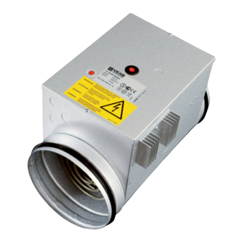
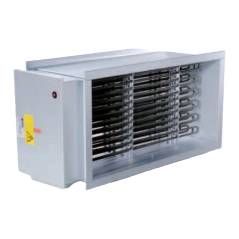
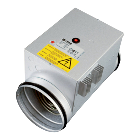
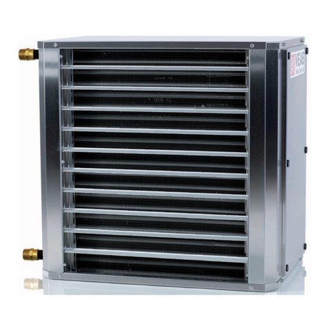
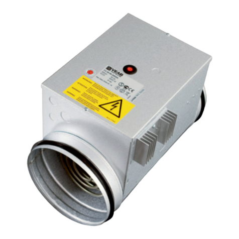
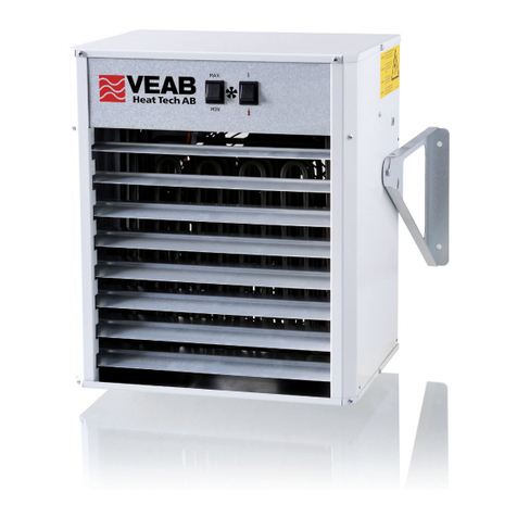
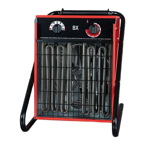
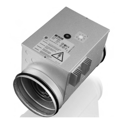
VEAB VFLPG User manual

VFLPG/VFL/VTL/VRA
Art.nr. 173223-02
Instrukcja
Nagrzewnica kanałowa, prostokątna z wbudowanym regulatorem temperatury
Uwaga: Przeczytaj tę instrukcję przed instalacją, podłączeniem i używaniem produktu
Zachowaj instrukcję na przyszłość ............................................................................................................................ 4
PL
GB Manual
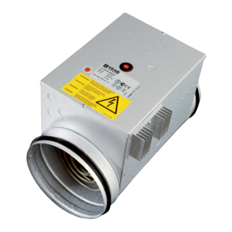
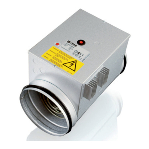
Rectangular duct heater with built-in temperature control
IMPORTANT: Read this manual before installing, connecting and using the product.
Save the manual for future reference................................................................................................7
.
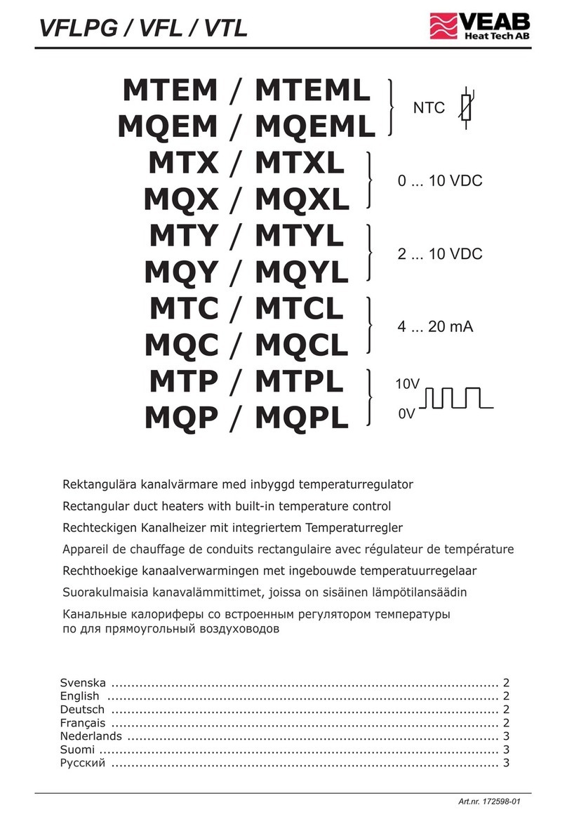
MTEM / MTEML NTC
MTX / MTXL 0...10 VDC
MTY / MTYL 2...10 VDC
MTC / MTCL 4...20 mA
MTP / MTPL 0V
10V

2
VFLPG/VFL/VTL/VRA
1. Informacje dotyczące bezpieczeństwa, instalacji, konserwacji, podłączenia, usterek ...............................4-6
2. Nagrzewnica z dwoma czujnikami, z których jeden to ograniczenie MIN i/lub MA X
-MTEM / -MTEML ......................................................................................................................................9-20
3. Nagrzewnica do sygnału wejściowego, sterującego, 0...10V (2...10V)
-MTX (-MTY) / -MTXL (-MTYL) ................................................................................................................21-23
4. Nagrzewnica do sygnału wejściowego, sterującego , 4...20mA
-MTC / -MTCL ........................................................................................................................................24-26
5. Nagrzewnica do sygnału wejściowego, puls/pauza , 0 lub 10V
-MTP / -MTPL .........................................................................................................................................27-29
Spis treści
1. Safety Information, installation, maintenance, overheating, trouble-shooting, connection .........................................6-8
2. Heater for two sensors, of which one is used for MIN- and/or MAX-limitation
-MTEM / -MTEML .............................................................................................................................................9 - 20
3. Heater for continous input signal, 0...10V (2...10V)
-MTX (-MTY) / -MTXL (-MTYL) ..................................................................................................................21-23
4. Heater for continous input signal, 4...20mA
-MTC / -MTCL ...................................................................................................................................................24-26
5. Heater for puls/paus input signal, 0 or 10V
-MTP / -MTPL ...................................................................................................................................................27-29
Table of contents

3
VFLPG/VFL/VTL/VRA
Informacje dotyczące bezpieczeństwa.
1. To urządzenie nie może być używane przez dzieci, osoby oograniczonych możliwościach fizycznych, sensorycznych,
umysłowych lub nie posiadające doświadczenia iodpowiedniej wiedzy chyba,że jest używane pod nadzorem osoby
odpowiedzialnej za ich bezpieczeństwo.
2. Wszystkie prace instalacyjne muszą być wykonywane przez osoby wykwalifikowane .
3. Dane techniczne nagrzewnicy dotyczące napięcia iprądu są na schemacie elektrycznym umieszczonym na
wewnętrznej stronie pokrywy skrzynki podłączeniowej. Na schemacie podane są też informacje dotyczące
zabezpieczeń termicznych.
4. Dozwolona temperatura otoczenia to: -20 °C ... +30°C. Nagrzewnica jest zaprojektowana dla maksymalnej
dozwolonej temperatury, która również jest podana na tabliczce znamionowej.
5. Nagrzewnica musi być podłączona do prądu kablem okrągłym zainstalowanym na stałe. Użyć odpowiednich dławików
kablowych wcelu spełnienia wymogów klasy ochrony elektrycznej. Standardowa konstrukcja to IP43. Na życzenie może
być wyprodukowana wersja oklasie ochrony IP55. Wtakim przypadku ta informacja jest zamieszczona na tabliczce
znamionowej. Konstrukcja IP55 jest dostarczana zfabrycznie zamontowanymi dławikami kablowymi.
6. Nagrzewnica nie może być uruchomiona przed włączeniem wentylatora. Wyłączenie wentylatora musi być możliwe
tylko po wcześniejszym wyłączeniu zasilania nagrzewnicy lub przy wyłączeniu wtym samym momencie. Jeżeli moc
znamionowa jest większa niż 30 kW, nagrzewnica powinna być wyłączana na co najmniej 3minuty przed wyłączeniem
wentylatora. W ten sposób można zagwarantować, że zabezpieczenie przed przegrzewaniem nie zostanie włączone
pod wpływem ciepła powyłączeniowego.
7. Prędkość powietrza przechodzącego przez nagrzewnicę musi wynosić co najmniej 1,5 m/s przy maksymalnej temp.
wylotowej =50°C.
8. Nagrzewnica jest oznaczona znakiem CE iprodukowana wg norm: EN 60335-1 lEN 60335-20 lEN 61000-6-2 /EN
61000-6-3 /EN 62233.
9. Nigdy nie otweiraj nagrzewnicy kiedy jest ona podłączona do zasilania.
PL

4
VFLPG/VFL/VTL/VRA
Instalacja.
l. Jeżeli nagrzewnica nie jest wykorzystywana wokresie 3miesięcy, magazynuj ją wsuchym pomieszczeniu
(maks. 40% RH).
2. Nagrzewnice VFLPG/VFL/VTL są zaprojektownae do montażu isntalacjach kanałowych. Nagrzewnica VRA jest
przeznaczona jesy do montażu wcentralach wentylacjnych.
3. Powietrze musi przepływać przez nagrzewnicę wkierunku wskazywanym przez strzałkę znajdującą się na
pokrywie skrzynki rozdzielczej.
4. Nagrzewnicę można instalować wkanałach poziomych lub pionowych, ze skrzynką rozdzielczą skierowaną w
bok. Niedozwolony jest montaż ze skrzynką skierowaną do góry lub do dołu.
5. Na otworze wlotowym do pomieszczenia,musi być zamontowana nastałesiatka lub czerpnia powietrza
wlotowego, uniemożliwiającadotknięcie elementów grzejnych.
6. Wpobliżu wylotu powietrza umieścić tabliczkę ostrzegawczą informującą otym, żewylot powietrza nie może
być zakryty.
7. Odległość od (do) nagrzewnicy do (od) łuku kanału, zaworu, filtra itd. powinna wynosić co najmniej tyle, co
długość przekątnej nagrzewnicy, mierzona od narożnika do narożnika po stronie kanału. Wprzeciwnym
razie istnieje ryzyko, żestrumień powietrza przepływający przez nagrzewnicę będzie nierówny, co może
spowodować aktywację wyłącznika przegrzania. Przykład: Wkanałach owymiarach 800 x400 mm odległość
powinna wynosić co najmniej 900 mm (wprzybliżeniu).
8. Nagrzewnica kanałowa może być izolowana zgodnie zobowiązującymi regulacjami dotyczącymi kanałów
wentylacyjnych. Izolacja musi być jednak niepalna. Izolacja nie może zakrywać pokrywy, ponieważ tabliczka
znamionowa musi być widoczna, musi być możliwe zdjęcie pokrywy. Grozi to też przegrzewaniem elementów w
skrzynce.
9. Nagrzewnica kanałowa musi być dostępna na potrzeby wymian iprzeglądów.
10. Odległość między metalową obudową nagrzewnicy adrewnem lub innymi materiałami palnymi NIE MOŻE być
mniejsza niŻ 100 mm.
Konserwacja.
l. Nie jest wymagana żadna konserwacja zwyjątkiem okresowej kontroli działania idokręcenia zacisków zasilania
sieciowego co najmniej raz na rok.
2. Aby utrzymać izolację elementu grzewcego nagrzenwica musi pracować przynajmniej przez 24 godziny po
każdych 3miesiącach.
Przegrzanie. Jeżeli został aktywowany wyłącznik przegrzania zręcznym resetem, należy przestrzegać
następujących zaleceń:
l. Pokrywa może być zdejmowana wyłącznie przez elektryków zuprawnieniami.
2. Sieciowe napięcie zasilania musi być wyłączone
3. Ostrożnie zbadać przyczynę aktywacji wyłącznika przegrzania.
4. Po wyeliminowaniu usterki można zresetować wyłącznik przegrzania.
Rozwiązywanie probelmów:
MTEM / -MTEML
• Skontroluj czy wybrany czujnik jest właściwy i czy jest podłączony w sposób prawidłowy.
• Skontroluj czy wybrano właściwą funkcję pracy regulatora Pulser lub TTC.
• Skontroluj rezystancję czujnika i nastawnika wartości zadanej. Odłącz je z terminali przed jakimkolwiek pomiarem.
Czujniki dla 0...30°C powinny mieć rezystancję 10k @ 30°C, 11.7k @ 20°C i 15k @ 0°C.
Zewnętrzny nastawnik wartości zadanej powinien mieć rezystancję 0...5k.°C
Pełne grzanie bez regulacji:
- Deaktywuj funkcję ograniczenia temp., jeżeli jest aktywowana, upewnij się, że złączki ”MIN” i ”MAX” są otwarte.
- Zewrzyj “na krótko” styki terminala dla czujnika głównego. Jeżeli grzanie jest teraz wyłączone, to problem jest w czujniku
zewnętrznym.

5
VFLPG/VFL/VTL/VRA
Brak grzania.
•Sprawdzić, czy został aktywowany wyłącznik przegrzania z ręcznym resetem. Jeżeli tak, wyeliminować usterkę i zresetować go.
Dalsze informacje są dostępne w rozdziale ,,Przegrzanie”.
•Sprawdzić wyłączniki przegrzania i elementy grzejne przez pomiar.
•Sprawdzić, czy bloki zaciskowe nagrzewnicy znajdują się pod napięciem sieciowym. Sprawdzić urządzenia blokujące, bezpieczniki,
przerywacze, itd.
•Odłączyć czujniki od zacisków. Jeżeli nagrzewnica się uruchomi, usterka znajduje się w zewnętrznym zespole obwodów czujnika. W
przeciwnym razie usterka znajduje się w regulatorze (pulsator/TTC).
MTX / -MTXL (-MTY / -MTYL)
MTC / -MTCL
MTP / -MTPL
•Upewnić się, że sygnał sterujący ma prawidłową biegunowość.
Pełna moc grzania bez możłiwości regulacji.
•Odłączyć okablowanie sygnału sterującego i połączyć/zewrzeć zaciski wejściowe sygnału sterującego. Jeżeli to
spowoduje wyłączenie ogrzewania, usterka znajduje się w zewnętrznym sygnale sterującym.
Brak grzania
•Sprawdzić, czy został aktywowany wyłącznik przegrzania z ręcznym resetem. Jeżeli tak, wyeliminować usterkę i
zresetować go. Dalsze informacje są dostępne w rozdziale ,,Przegrzanie”
•Sprawdzićwyłączniki przegrzania i elementy grzejne przez pomiar.
•Sprawdzić, czy bloki zaciskowe nagrzewnicy znajdują się pod napięciem sieciowym. Sprawdzić urządzenia blokujące,
bezpieczniki, przerywacze itd.
•Odłączyć okablowanie sygnału sterującego i podłączyć ogniwo akumulatora 9 V lub inne odpowiednie
ŹrÓdło napięcia jako sygnał sterujący, jeżeli typ nagrzewnicy to -MTX l -MTXL l -NITY l -MTYL l -MTP l -MTPL .
Jeżeli nagrzewnica jest typu -MTC l -MTCL, należy podłączyć szeregowo rezystor 470 z ogniwem akumulatora 9 V
jako sygnałem sterującym. Jeżeli nagrzewnica się nie uruchomi, usterka znajduje się w regulatorze (Pulser/TTC).
Podłączenie.
1.Nagrzenwicakanałowa jest wyposażona zzabezpieczenie termiczne. Ich ilość inastawa zależy od wymiarów i
intensywności użytkowania.
2.Nagrzewnica może być wyposażona wzabezpieczenie termiczne, które ma funkcję stylu przemiennego lub inaczej
przekaźnik może być uwzględniony wpodłączeniu. Alternatywnie styki lub styki przekaźnika mogą być wykorzystane w
funkcji alarmu do wskazania aktywacji zabezpieczenia termicznego. Złącza przekaźnika nie powinny być używane do
interlockingu, tylko do wskazań.
3.Nie jest rekomendowane, aby funkcja zabezpieczenia przed przegrzaniem byłakontrolowana przez obwód
elektroniczny. To musi być tak wykonane, aby odcięcie zasilania nastąpiło jeżeli zadziała zabezpieczenie termiczne.
4. Nagrzewnia możemieć kilka stopni mocy, które są przedstawione na schemacie elektrycznym umieszczonym na
wewnętrznej części pokrywy.
5.Ponieważ w nagrzewnicach typu -MTEM/-MTEML o prądzie znamionowym mniejszym lub równym 40 A zespół
obwodów elektrycznych czujnika nie jest oddzielony galwanicznie od źródła zasilania sieciowego, należy zachować
ostrożność podczas podłączania czujników/nastawy wartości zadanej ze względu na poziom napięcia sieciowego.
6.W nagrzewnicach typu -MTEM/-MTEML z napięciem sieciowym znamionowym > 415V 3- (≤ 40A) czujnik kanału
musi być przymocowany na stałe w kanale w taki sposób, aby jego wyjęcie bez narzędzi było niemożliwe; ponadto
należy zastosować czujnik pomieszczeniowy/nastawnik wartości zadanej typu TG-R930.
6
VFLPG/VFL/VTL/VRA
Safety Information
1. is appliance may be used by children aged eight years or above, people with physical and
mental disabilities as well as those who lack any experience, provided that they have received
detailed instructions about the functionality of the appliance and any risks. Children must not play
with the appliance.
Cleaning and maintenance must not be performed by children without proper supervision.
Children under three years of age should not be near the appliance without constant supervision.
Children between three and eight years old may only turn on/shut o the appliance if it is located
in a suitable position and they have received instructions about the proper course of action, or are
being supervised.
ey shall also be informed about possible dangers. Children between three and eight years old may
not connect the device, change its settings or perform care/maintenance.
2. All installation work must be carried out by a qualied technician.
3. e heater’s data for voltage and power is stated on the wiring diagram placed on the inside of the
cover as well as on the specication plate on the outside of the cover.
e wiring diagram also contains information regarding overheating protection.
4. e allowed ambient temperature is -20 °C ... +30°C. e heater has been designed for a maximum
allowed outgoing air temperature which is also stated on the rating plate.
5. e heater must be connected to the mains supply with a xed cable. An all phase switch must
be included in the xed installation. Conduit entries must be of a type that allows the heater’s
ingress protection class to be retained. e heater’s IP class is stated on the rating plate.
IP55/IP65 models are supplied with factory-installed cable glands.
6. e heater must be installed in such a way that it interlocks towards the overheating protection,
which is tted to the heater, and the fan or air stream that goes through the heater. e overheating
protection must also directly interrupt, without intermediate electronics, the control current for
relays/contacts that control the heat output. It must not be possible to supply power to the heater
without the fan previously having been turned on. It must also be impossible to turn o the fan
without interrupting the heater’s power supply. For outputs higher than 30 kW, it is recommended
that an after-blow period of at least 3 minutes is used before the fan is stopped. is is to ensure that
the overheating protection is not triggered by the remaining heat.
7. Air speed through the heater must be at least 1.5 m/s when the outgoing temperature is max. 50°C.
8. e heater has CE marking and is produced in accordance with EN 60335–1/EN 60335–20/EN
61000-6-2/EN 61000-6-3/EN 62233.
9. Never attempt to open the heater while it is connected to mains electricity.
GB

7
VFLPG/VFL/VTL/VRA
Installation
1. Heater VFLPG/VFL/VTL is designed for installation in duct systems. Heater VRA is designed for installation in a
ventilation device.
2. e direction of air through the heater must follow the air ow arrow on the heater.
3. e heater may be installed in a horizontal or a vertical duct, with the junction box to the side. Installation with the
junction box above or below is NOT allowed.
4. Inlets into rooms must be covered by a xed grill or air inlet unit that prevents the heating elements from being
touched in the case a protective grill is not installed on the heater.
5. A warning text regarding not covering the heater should be placed next to the outlet air opening.
6. e minimum distance to duct bends, dampers, lters etc. must be at least the same as the diagonal length of
the heater, i.e. the measurement from corner to corner of the heater’s duct section. Otherwise there is a risk for
irregularities in the air stream through the heater, which may trigger the overheat protection.
7. e heater may be insulated in accordance with applicable regulations for ventilation ducts/ventilation devices.
e insulation must consist of reproof insulation material. e insulation may not cover the lid as the rating
plate and warning sign must be visible and the lid must be accessible for opening. e heater must be accessible for
replacement and inspections.
8. e distance from the heater’s metal surface to wood or other ammable material may NOT be less than 100 mm.
Maintenance
1. In normal situations there is no need for maintenance. A periodic control of functions and re-tightening of power
supply connections must be carried out at least once per year.
2. To maintain isolation in the heating element, the power stage must be connected and run for 24h at least every 3
months.
Overheating
e heater contains at least two overheating protections (of which at least one is reset manually). If the overheating
protection that is reset manually is triggered, the following must be taken into consideration:
1. Cut o the power supply.
2. e heater’s lid may only be opened by a qualied technician.
3. oroughly investigate the cause for the overheating protection being triggered.
4. When the fault has been rectied, the overheating protection may be reset.
Trouble-shooting
- MTEM / -MTEML
• Check that the sensor is of the correct type and that its termination is made correctly.
• Check that the correct function for the Pulser or TTC is selected.
• Check the resistance of the sensor and the set value potentiometer. Disconnect them from the terminals before any
measurements is taken. Sensors for 0...30°C should have the resistance 10kΩ @ 30°C, 11.7kΩ @ 20°C and
• 15kΩ @ 0°C.
e external set point potentiometer should have the resistance 0...5kΩ.°C
Full heating power but no regulation
• Deactivate the limitation function, if it is activated, by making sure that the jumpers ”MIN” and ”MAX” are open.
• Strap/short-circuit the terminals for the main sensor.
If this results in the heating now being turned o, then the fault is in the external sensor circuitry.

8
VFLPG/VFL/VTL/VRA
No heating
• Check whether or not the overheating cut-out, with manual reset, has been activated. If it has, then eliminate the
fault and reset it. Read furthermore the paragraph ”Overheating” at page 8.
• Check the overheating cut-outs and the heating elements by measurment.
• Check whether or not there is mains voltage at the heater terminal blocks. Check the interlocking devices, fuses,
breakers, etc.
• Disconnect the sensor from the terminals.
If the heater starts now, then the fault is in the external sensor circuitry. Otherwise, the fault is in the regulator
(Pulser/TTC).
- MTX / -MTXL (-MTY / -MTYL)
- MTC / -MTCL
- MTP / -MTPL
• Make sure that the control signal has the correct polarity.
Full heating power but no regulation
• Disconnect the excitation signal wiring and strap/short-circuit the excitation signal input terminals. If this results in
the heating now being turned o, then the fault is in the external control signal.
No heating
• Check whether or not the overheating cut-out, with manual reset, has been activated. If it has, then eliminate the
fault and reset it. Read furthermore the paragraph ”Overheating” at page 8.
• Check the overheating cut-outs and the heating elements by measurment.
• Check whether or not there is mains voltage at the heater terminal blocks. Check the interlocking devices, fuses,
breakers, etc.
• Disconnect the excitation signal wiring and connect a 9V battery-cell or another suitable voltage source as a control
signal, if the type of heater is -MTX / -MTXL / -MTY / -MTYL / -MTP / -MTPL .
If the type of heater is an -MTC / -MTCL a 470Ω resistor has to be connected in series with the 9V battery-cell to
be used as an control signal.
If the heater doesn’t start now, then the fault is in the regulator (Pulser/TTC).
Connection
1. e duct heater comes with overheating protection. e number and their setting depend on the duct dimensions and
the intended usage.
2. Heaters may be supplied with overheating protection that has an alternating contact function, or otherwise a relay
may be included in the connection. Alternating contacts, or the relay connectors, can be used as an alarm function to
indicate that the overheating protection has been triggered. e relay connectors may not be used for interlocking,
only for indication.
3. e heater overheating protection must always be part of the control equipment circuit. It is not recommended that
the overheating protection function is controlled by an electronic circuit. It must be established that the heating
output is disconnected if the overheating protection is triggered.
4. e heater may have a number of power stages, which is indicated on the wiring diagram on the inside of the heater
cover.
5. As the sensor circuit for MTEM/MTEML type heaters with rated current ≤40 A is not galvanically separated from
the heater’s power supply, the sensors and set point potentiometers should be installed considering that they have
mains supply potential.
6. With rated voltage >415 V3~ for MTEM/MTEML type heaters with rated current ≤40 A, duct sensors must be
installed so that they cannot be removed without tools, see page 20. Room sensors/set point controllers must also be
of type TG-R930.
9
VFLPG/VFL/VTL/VRA
MTEM / MTEML
Nagrzewnice z wbudowanym regulatorem z zewnętrznym nastawnikiem
•Nagrzewnica kanałowa posiada wbudowany regulator tyrystorowy.
•Zarówno czujnik główny jak i czujnik MIN i/lub MAX są podłączane do nagrzewnicy.
•Nagrzewnica posiada wbudowane ręczne zabezpieczenie przed przegrzaniem z przyciskiem reset na pokrywie
skrzynki podłączenowej.
Duct heater with built-in regulator for external set point adjustment
• e duct heater has a built-in thyristor control.
• Both the main sensor and the sensor for the MIN and/or MAX function are connected to the heater.
• e heater has a built in manual reset thermal protection with the reset button placed on the lid.

10
VFLPG/VFL/VTL/VRA
UWAGA !
Płytka PCB jest pod napięciem, kiedy nagrzewnica jest podłączona do zasilania.
B = Zworka (Int/Ext) musi być zwarta.
C = Potencjometr dostrojczy ustawiony jest fabrycznie. Nie regulować!
D = Ustawnienie wartości zadanej dla ograniczenia temp. minimalnej.
E = Ustawnienie wartości zadanej dla ograniczenia temp. maksymalnej.
F = Zworka (MAX) musi być ZWARTA, aby aktywować funkcję ograniczenia temp. MAX.. OTWARTA w celu dezaktywacji funkcji.
G = Zworka (MIN)musi być ZWARTA, aby aktywować funkcję ograniczenia temp. MIN. OTWARTA w celu dezaktywacji funkcji.
Czerwona dioda przy zasilaniu 1 i 2 -fazowym lub dwie czerwone diody przy zasilaniu 3-fazowym wskazują, że elementy grzewcze są aktywne.
WARNING !
e PCB is at mains voltage level when the heater is connected to mains.
B = Jumper (Int/Ext) must be SHORTED.
C = Trim potentiometer set at manufactoring. Do NOT adjust!
D = Set point adjustment for MIN. temperature limitation.
E = Set point adjustment for MAX. temperature limitation.
F = Jumper (MAX) must be SHORTED to activate MAX. temperature limitation function. OPEN jumper deactivates the function.
G = Jumper (MIN) must be SHORTED to activate MIN. temperature limitation function. OPEN jumper deactivates the function. A red LED, at
1 and 2 phase supply, or two red LEDs, at 3 phase supply, indicates that the heating elements are activated.

11
VFLPG/VFL/VTL/VRA
D = Re g u la c ja temperatury ( tyrystorowa )
Temperature regulator ( thyristor control )
E = ”Blokada” tzw, Interlocking
F = Łącznik pomocniczy
Control switch
G = Styki przekaźnika alarmowego wskazujące włączenie zbezpieczenia
przed przegrzaniem
Alarm relay contacts to indicate activated over heat protection
NO = Styk normalnie otwarty ( zwiera się przy przegrzaniu )
Normally Open contact ( closes at over heating )
K/J = Łączony nastawnik wartości zadanej oraz czujnik pokojowy
( TG-R430 eller TG-R930 )
Combined set point adjustment and room sensor
( TG-R430 or TG-R930 )
K =
Nastawnik wartość zadnej ( * TG-R430, TG-R930 lub ** TBI-30 )
Set point adjustment ( * TG-R430, TG-R930 or ** TBI-30 )
J =
Czujnik główny ( TG-K330, TG-K930, TG-R530 eller TG-R630 )
Main sensor ( TG-K330, TG-K930, TG-R530 or TG-R630 )
M =
Czujnik ograniczający ( T G -K 36 0 lub T G-K 9 6 0 )
Limitation sensor ( TG-K360 or TG-K960 )
T =
Przełącznik ciśnienia lub przepływu ( op cj a )
Pressure switch or air ow switch ( optional )
NC = Styk normalnie zwarty ( otwiera się przy przegrzaniu )
Normally Closed contact ( opens at over heating )
Zasilanie sterujące
Control voltage
Zasilanie (patrz na tabliczkę znamionową)
Supply voltage (see the rating plate)
Podłączenia obwodów czujników
Alternative sensor circuit

12
VFLPG/VFL/VTL/VRA
Zespół obwodów czujnika
Regulacja temp. w pomieszczeniu
Regulacja temperatury w pomieszczeniu
z oddzielnym czujnikiem
Regulacja temperatury naiwewu
Czujnik główny
PL
Nastawnik
Łączony nastawnik
i czujnik
Czujnik ogranicz.
Limit MIN
Zwarty = aktywny
Otwarty = nieaktywny
Limit MAX
Zwarty = aktywny
Otwarty = nieaktywny
Potencjometr limitu
MIN 0 ....30C
Potencjometr
limitu MAX 20
.......60C

13
VFLPG/VFL/VTL/VRA
Regulacja temperatury pomieszczenia
z ograniczeniem temp. na wlocie MIN i MAX
Regulacja temp. pomieszczenia z oddzielnym
czujnikiem pokojowym i z temp powietrza na
wlocie MIN i MAX

14
VFLPG/VFL/VTL/VRA
UWAGA !
Płytka PCB jest pod napięciem, kiedy nagrzewnica jest podłączona do zasilania.
1 = Przełącznik do wyboru nastawnika wewnętrzego lub zewnętrznego. Normalnie ustawiony na OFF
2 = Przełącznik do aktywacji lub dezaktywacji funkci ograniczenia temp. MIN.
3 = Przełącznik do aktywacji lub dezaktywacji funkci ograniczenia temp. MAX.
Min = aby włączyć ogranicznie MIN przełącznik 2 musi być ON.
Max = aby włączyć ogranicznie MAX przełącznik 3 musi być ON..
Nastawa = wewnętrzyn nastawnik jest przy przełączniku 1 w pozycji ON.
Czerwona dioda świeci się keidy elementy grzewcze są aktywne.
WARNING !
e PCB is at mains voltage level when the heater is connected to mains.
1 = Switch to choose internal or external set point adjustment. Normally set to OFF.
2 = Switch to activate or deactivate the MIN. temperature limitation function.
3 = Switch to activate or deactivate the MAX. temperature limitation function. Min = Set value adjustment
for MIN. temperature limitation if 2 is set to ON. Max = Set value adjustment for MAX. temperature
limitation if 3 is set to ON. Setp = Internal set point adjustment if 1 is set to ON.
A red LED indicates that the heating elements are activated.

15
VFLPG/VFL/VTL/VRA
D = Regulacjatemperatury ( tyrystorowa )
Temperature regulator ( thyristor control )
E = ”Blokada”tzw,Interlocking
F = Łącznik pomocniczy
Control switch
G = Styki przekaźnika alarmowego wskazujące włączenie zbezpieczenia
przed przegrzaniem
Alarm relay contacts to indicate activated over heat protection
NO = Styk normalnie otwarty ( zwiera się przy przegrzaniu )
Normally Open contact ( closes at over heating )
K/J = Łączony nastawnik wartości zadanej oraz czujnik pokojowy
( TG-R430 eller TG-R930 )
Combined set point adjustment and room sensor
( TG-R430 or TG-R930 )
K = Nastawnikwartość zadnej ( * TG-R430, TG-R930 lub ** TBI-30 )
Set point adjustment ( * TG-R430, TG-R930 or ** TBI-30 )
J = Czujnik główny ( TG-K330, TG-K930, TG-R530 eller TG-R630 )
Main sensor ( TG-K330, TG-K930, TG-R530 or TG-R630 )
M = Czujnik ograniczający ( TG-K360 lub TG-K960 )
Limitation sensor ( TG-K360 or TG-K960 )
T = Przełącznik ciśnienia lub przepływu ( opcja )
Pressure switch or air ow switch ( optional
NC = Styk normalnie zwarty ( otwiera się przy przegrzaniu )
Normally Closed contact ( opens at over heating )
Podłączenia obwodów czujników
Alternative sensor circuit
Zasilanie (patrz na tabliczkę znamionową)
Supply voltage (see the rating plate)
Zasilanie sterujące
Control voltage

point
point
point
MIN limitation
MIN limitation
MAX limitation
MAX limitation
16
VFLPG/VFL/VTL/VRA
Zespół obwodów czujnika PL
J Czujnik główny
K Nastawnik
K/J Łączony nastawnik z
czujnikiem pokojowy
M Ograniczenie temp.
S1 Nastawa temp:
On = wewnętrzna (P1)
OFF = zewnętrzn. (K)
S2 Limit MIN
On = aktywny
Off = nieaktywny
S2 Limit MAX
On = aktywny
Off = nieaktywny
P1 Wewnętrzny potencjometr
wartości zadanej 0...30C
P2 Potencjometr ograniczenia
temp. MIN 0...30C
P3 Potencjometr ograniczenia
temp. MAX 20...60C
P4 Nastawa fabryczna
NIe regulaować !
Regulacja tempertury w pomieszczeniu
Regulacja temperatury z oddzielnym
czujnikiem
Regulacja temperatury nawiewu

17
VFLPG/VFL/VTL/VRA
Regulacja temp. w pomieszczeniu z
ograniczeniem temp. MIN i MAX
Regulacja temp. w pomieszczeniu z
oddzielnym czujnikiem i ograniczeniem
temp. MIN i MAX

18
VFLPG/VFL/VTL/VRA
MTEM / MTEML
•Montaż czujników kanałowych dla napięcia znamionowego >415V 3~.
• Fixation of duct sensors for heaters with rated voltage >415V 3~.
•Po pierwsze wywierć otwór o średnicy 10mm i przymocuj podkładkę do kanału za pomocą wkrętów lub
nitów.
• First drill a 10mm diameter hole and attach the washer to the duct. Fix it with screws or pop-rivets.

19
VFLPG/VFL/VTL/VRA
•Zamontuj metalowy element montażowy i przelotkę kablową. Dokręć nakrętkę przelotową tak,
aby nie poluzowała się bez użycia narzędzi.
• Assemble the sheet metal xation part and the cable grommet. Tighten the grommet nut, with
such a torque that it can not be loosen without the use of tools.
• Włóż czujnik kanałowy (razem z elementem
montażowym) do kanału
• Insert the duct sensor, assembled with the sheet
metal xation part, into the duct.

20
VFLPG/VFL/VTL/VRA
•Przymocuj element montażowy do kanału za pomocą wkrętó lub nitów.
Dopasuj głębokość zanurzenia i dokręć nakrętkę przelotową tak, aby nie poluzowała się bez użycia
narzędzi.
• Anchor the sheet metal xation part to the duct with two screws or pop-rivets.
Adjust the insertion depth and tighten the grommet, with such a torque that it can not be loosen without the
use of tools.
Other manuals for VFLPG
6
This manual suits for next models
13
Table of contents
Other VEAB Heater manuals
Popular Heater manuals by other brands

Rohnson
Rohnson R-8013 instruction manual

Plumbline
Plumbline Progetto Series installation instructions

EOS
EOS Herkules XL S120 HD Installation and operating instructions

Toyostove
Toyostove Laser 530 Assembly, installation and operation instructions

Gabarron
Gabarron Elnur ECOMBI HHR Series installation instructions

STIEBEL ELTRON
STIEBEL ELTRON ETT 500 electronic Operating and installtion instructions