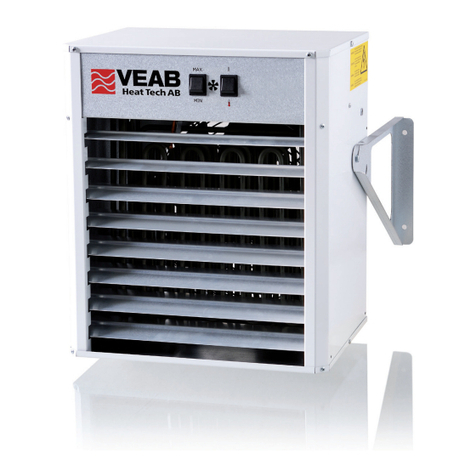
VEAB AW 13s-63s User manual

Art.nr. 173391-01
AW 13s-63s, 13a-63a
Handbuch für Lufterhitzer, Wasser
WICHTIG: Lesen Sie die Betriebsanleitung, bevor Sie das Gerät montieren, anschliessen und in
Betrieb nehmen Bewahren Sie die Betriebsanleitung für den zukünftigen Betrieb auf..............18
Manual for fan heaters unit, water
IMPORTANT: Please read this manual before installing, connecting and putting the product into use.
Save the manual for future use....................................................................................................10
Manual för värmeäkt vatten
VIKTIGT: Läs denna manual innan produkten monteras, ansluts och tas i bruk.
Spara manualen för framtida bruk ...................................................................................................... 2
SE
GB
DE

AW 13s-63s, 13a-63a
2
Säkerhetsinformation
Denna apparat får användas av barn över 8 år, personer med fysiska- eller psykiska funktionshinder samt
personer som saknar erfarenhet, men endast under förutsättning att de har fått noggranna instruktioner om
apparatens funktioner och eventuella risker. Barn får ej leka med apparaten. Rengöring och underhåll får ej
utföras av barn utan att de har tillsyn. Barn under tre år ska inte vara i närheten utan ständig tillsyn.
Barn mellan tre och åtta år får endast sätta på/stänga av apparaten om den står på lämplig plats och de har
fått instruktioner om tillvägagångssätt eller har tillsyn. De ska också informeras om möjliga faror.
Barn i åldern tre till åtta år får inte sätta i kontakten, ändra inställningar eller utföra skötsel/underhåll.
VARNING – Delar av denna apparat kan bli varma och orsaka brännskador.
Barn och sårbara personer ska hållas under uppsikt.
Värmefläkten finns i fyra storlekar AW 13, AW 23, AW 43 och AW 63.
AW-s i EC utförande har endast fullvarv på fläkten, medan övriga modeller har tre fläktvarvtal.
Värmefläkten i AC utförande och AW 63 EC är i kapslingsklass IP 44. Övriga EC fläktar är i kapslingsklass IP 54.
Båda kapslingsklasserna medger installation i torra, fuktiga och våta rum. Modell AW-a levereras med ventil.
För teknisk data på värmefläktarna se bilaga A.
AW 13s, -23s, -43s, -63s.
Dessa värmefläktar har ingen inbyggd reglering. Styrningen av fläktmotor och vatten löses med externa komponenter.
I lokaler där frostrisk föreligger skall frysskydd installeras.
AW 13a, -23a, -43a, -63a.
Värmefläkten har inbyggd reglering och används där frysrisk ej föreligger. I värmefläkten finns en elektronisk tre-
stegstermostat som reglerar fläktens varvtal i tre steg efter rådande värmebehov. Termostaten arbetar med intermittent
fläktdrift, dvs. även fläktmotor stannar när inget värmebehov finns. Detta medför att nedsmutsningen av vattenbatteri
och eventuella filter minimeras. Även varvtalsregleringen som håller fläkten på lägsta möjliga luftmängd minskar
nedsmutsningen. Trestegsregleringen medför också att värmefläkten stora delar av året klarar sig på de lägre varvtalen
och man får därför en låg ljudnivå. Vattenflödet regleras on/off av en ventil med påbyggt ställdon.
Öppnings- resp. stängningstid är 15 sek. Ventilen öppnar samtidigt som fläkten startar på lågvarv.
Till regleringen behövs en rumsgivare med börvärdesinställare (TG-R430) eller rumsgivare (TG-R530 eller TG-
R630) med separat börvärdesinställare (TG-R430). Stegdifferens på termostaten är 1°C.
Som alternativ till TG-givare kan en extern 0... 10V DC styrsignal kopplas till den elektroniska termostaten.
AW-a har också en utgående styrsignal. Denna funktion finns oberoende om man använder TG-givare eller
inkommande 0... 10V DC styrsignal. Den utgående styrsignalen kan slavstyra upp till fem andra AW-a eller CAW-a.
(CAW-a är VEABs serie av takmonterade värmefläktar). Vill man slavstyra fler än 5st värmefläktar från gemensam
givare eller 0... 10V DC styrsignal använder man utgånde styrsignal från en slavstyrd AW-a.
Exempel på inkoppling av givare eller styrsignal finns på bilaga F, G, H och N (J, L och M för EC) i denna folder.
SE
Tillbehör AW a-s (se bilaga B)
Filter AWPF.
Planfilter för montage i AW13-63 mellan fläkt
och vattenbatteri.
Luftriktare AWLH.
På värmefläkten sitter som standard alltid en luftriktare
som riktar luften snett nedåt. Som tillbehör finns
luftriktare AWLH som riktar luften i sidled.
Luftaccelerator AWLA
Förlänger kastlängden med i snitt 40%.
Kan ej användas tillsammans med AWLH.
Monteras enl. separat anvisning.
Vä ggkonsol AW V.
Användes för montage av värmefläkten på vägg eller
montage i taket med vertikal luftström.
Takkonsol AWT.
Användes för montage av värmefläkten i tak med
horisontell luftström.
Kan även användas ihop med väggkonsol.

AW 13s-63s, 13a-63a
3
Montering av lter AWPF.
1. Skruva av locket eller botten.
2. För in filtret genom öppningen och fäst först sidan med äderdelen, se bild 1.
3. Placera filtrets äderdel mot batteriets plåtkant, tryck sedan filtret mot andra sidan av vattenbatteriet
så att filtrets U-profil greppar vattenbatteriets bortre kant, se bild 2.
Luftriktare för luft i sidled AWLH.
1. Montera luftriktaren på värmefläkten med plåtskruv enl. bild 3 och 4.
Justera luftriktarbladen så att önskad luftriktning erhålles.
Montering av väggkonsol AWV.
1. Montera konsolerna enl. bild 5.
Bild 5
Bild 1 Bild 2
Bild 4
Bild 3

AW 13s-63s, 13a-63a
4
3. Värmefläkten kan monteras med rören åt vänster eller höger framifrån sett enl. bild 6 och 7.
I lokaler med hög takhöjd bör värmefläkten monteras lågt, dock utan att störa arbetsmiljön. Borrmall för
värmefläktarnas väggkonsol med minavstånd till golv, tak respektive vägg, se bilaga C.
4. Värmefläktarna levereras med luftriktaren monterad för montage enl. bild 6. Om värmefläkten monteras med
rören åt höger måste luftriktaren vändas om luften skall riktas nedåt. Lossa de sex skruvarna som håller
luftriktaren enl. bild 8 och tag ut luftriktaren och vrid den ett halvt varv. Skruva därefter fast den igen.
5. Vid montering i tak för vertikal luftström monteras värmefläkten enl. bild 9. Minsta avstånd till vägg bör vara
700 mm. Om värmaren monteras i tak nära ett vägghörn, bör minsta avståndet till ena väggen vara 700 mm och
andra väggen minst 2000 mm.
Montering av takkonsoler AWT.
1. Skruva ut plåtskruvarna enl. bild 10 (på AW 43 och AW 63 tre skruvar).
2. Montera takkonsolerna enl. bild 11.
Bild 6 Bild 7
Bild 8 Bild 9
Bild 10 Bild 11

AW 13s-63s, 13a-63a
5
3. Montera värmefläkt med takkonsoler i taket enl. bild 12 och 13.
4. Minsta avstånd från värmefläktens bakkant till vägg (pil bild 12) på AW 13 och AW 23 är 200mm.
På AW 43 och 63 är minavståndet 270mm.
5. Minsta avstånd från värmefläktens sida till vägg (pil bild 13) är 700mm.
Vattenanslutning av AW-s och AW-a.
VARNING! Kontrollera noga att hela systemet är tätt efter vattenanslutningen.
Eventuellt läckage kan förorsaka dyrbara vattenskador.
1. Värmefläkten får ej anslutas till tappvarmvatten eller ånga. Högsta tillåtna temperatur och tryck är angivet på
värmefläktens typskylt vid anslutningsrören.
2. Kapacitet, vattentemperatur, flöde och tryckfall kan utläsas via webben på VEAB Select.
3. Värmefläkten skall anslutas så att man vid driftsstopp när frysrisk föreligger, kan tömma batteriet på vatten.
4. Vid värmefläktens utloppsrör eller centralt i anläggningen monteras avluftningsventil.
5. Vid återdragning av klämringskopplingar på anslutningsrör eller ventiler skall dessa hållas fast, så att vridkraft
ej överförs till värmefläktens in- och utloppsrör.
6. Anslutet rörsystem till värmefläkten måste fixeras så att de ej belastar fläktens in- och utloppsrör.
7. Vatteninloppet ansluts på värmarens lägst placerade rör och utloppet på det högst placerade enl. pilar bild 14.
Anslutningen på AW 13- AW 23 är Ø 22mm och på AW 43- AW 63 Ø 28mm.
Anslutning med hjälp av presskoppling eller klämringskoppling rekommenderas.
Om röranslutningen skall lödas, måste röret innanför lödstället kylas (med exempelvis våt trasa, kylbackar eller
trycklyft) så att packningen innanför plåten (pil A bild 15) ej blir varmare än 100°C.
Tag bort stödhylsan innan lödning för att minska värmebehovet.
8. Vid anslutning med presskoppling eller klämringskoppling skall stödhylsa användas pga. att kopparrören är
mjukglödgade. Kontrollera att istoppad stödhylsa sitter i enl. pil B bild 15.
Montera kopplingarna enl. tillverkarens anvisningar.
Bild 12 Bild 13
B
A
Bild 14 Bild 15

AW 13s-63s, 13a-63a
6
9. På AW-a modellerna bör medföljande ventil (tillbehör på AW-s) monteras på det översta röret (utloppet), för att
få lägsta temperaturen på ventilen enl. bild 16. Ventilen skall monteras horisontalt med oberoende flödesriktning.
Anslutningen till ställdonet riktas rakt upp för att ställdonets IP-klassning ska bibehållas.
Drag åt ventilens klämringskopplingarna för hand och sedan 1 varv. Lossa därefter muttern ¼ varv för att avlasta
kopplingen från spänningar. Dra åter muttern så att kopplingen blir tät.
För mer information om ventilen, se monteringsanvisning som följer med ventilen.
Bild 16

AW 13s-63s, 13a-63a
7
Elanslutning AW-s modeller.
1. Installationen skall utföras av behörig installatör.
2. Värmefläkten är utförd för 230V växelström.
3. Elanslutning till nätet skall göras med fast förlagd kabel. Allpolig brytning med brytavstånd på minst 3 mm skall
ordnas i den fasta installationen.
4. Lossa locket till kopplingslådan.
5. Inkoppling av värmefläkt och val av varvtal görs enl. bifogat kopplingsschema i locket, se bild 17 eller bilaga D
(för EC bilaga I).
6. Borra det antal hål som behövs för installation i kopplingslådan och montera kabelgenomföring.
7. Termostaten som skall styra värmefläkten, bör monteras så att den ej påverkas av drag från dörrar och fönster som
öppnas, värmefläktens utblåsningsluft eller dyl.
Elanslutning av originaltillbehör för AW-s modeller.
1. Termostat R31 (bild 20) med temperaturområde 7-30°C och skyddsform IP20.
En termostat kan styra en AW-s värmare.
2. Termostat SR121/1 (bild 21) med temperaturområde 0-40°C och skyddsform IP54.
En termostat kan styra max två AW-s värmare.
Bild 20 R31 Bild 21 SR121/1
Bild 17
Bild 18 Bild 19

AW 13s-63s, 13a-63a
8
3. Varvtalsomkopplare AWC 13-63 med tre varvtal (bild 22) som väljs manuellt.
1 = lågvarv, 2 = mellanvarv och 3 = högvarv. Skyddsform IP 65.
Kan styra max 2 st AW-s värmare. Kopplingsschema se bilaga E.
OBS! Om termostat R31 eller SR121/1 används kan max en resp. två AW-s värmare kopplas in.
4. Varvtalsomkopplare för EC motor SMT-D-4P-EM med tre varvtal (bild 23) som väljs manuellt.
0 = stopp, 1 = lågvarv, 2 = mellanvarv och 3 = högvarv. Skyddsform IP44/54.
Kan styra max 5 st AW-s EC värmare. Kopplingsschema se bilaga K.
OBS! Om termostat R31 eller SR121/1 används kan max
en resp. två AW-S EC värmare kopplas in.
5. Ventil med kapslingsklass IP44 (bild 24), max vattentemperatur 90°C och tryckklass PN25 (25 bar).
Används tillsammans med termostat R31, SR121/1.
Mer information finns under ”Vattenanslutning av AW-s och AW-a” punkt 9.
Elanslutning AW-a modeller
1. Installationen skall utföras av behörig installatör.
2. Värmefläkten är utförd för 230V växelström.
3. Elanslutning till nätet skall göras med fast förlagd kabel. Allpolig brytning med brytavstånd på minst 3 mm skall
ordnas i den fasta installationen.
4. Lossa locket till kopplingslådan.
5. Inkoppling av värmefläkt görs enligt bifogat kopplingsschema i locket se bild 25 eller se bilaga F
(för EC bilaga J).
Bild 22 AWC 12-62 Bild 23 SMT-D-4P-EM Bild 24 AWTV 13-63
Bild 25

AW 13s-63s, 13a-63a
9
Bild 26 Bild 27
Bild 28 TG-R430 Bild 29 TG-R530 Bild 30 TG-R630
6. Borra det antal hål som behövs för installation i kopplingslådan och montera kabelgenomföring.
7 Till den inbyggda elektroniska termostaten i AW-a, ansluts en rumsgivare med börvärdesinställare TG-R430
(se bild 28) som har skyddsform IP30. Rumsgivaren/börvärdesomställaren bör monteras så att den ej påverkas av
drag från dörrar och fönster som öppnas, värmefläktens utblås eller dyl. Om man vill ha en separat rumsgivare,
väljer man TG-R530 (se bild 29) och monterar sedan börvärdesinställaren TG-R430 på annan plats.
Behövs högre skyddsform på givaren väljer man TG-R630 (se bild 30) som har skyddsform IP 54 och monterar
börvärdesinställaren i en plastkappsling med motsvarande skyddsform.

AW 13s-63s, 13a-63a
10
Rengöring
För att erhålla optimal funktion måste värmefläkten rengöras regelbundet.
Dammbeläggning på vattenbatteriets aluminiumlameller minskar luftflödet och försämrar värme-överföringen.
Batteriet måste därför hållas rent, vilket kan ske med hjälp av nedanstående alternativ:
1. Renblåsning med tryckluft
2. Renblåsning med ånga
3. Spolning eller sköljning med vatten. Vid fettbelagda lameller tillsätt lämpligt tvättmedel.
I alternativ 2 och 3 skall fläktmotorerna skyddas mot vatten. Vid rengöring skall värmefläkten göras spänningslös,
luftriktare och rengöringslucka tas bort.
Rengör även fläktens skyddsgaller och fläktvinge med en mjuk borste.
Tidsintervallerna mellan varje rengöring beror på vilken miljö som fläkten arbetar i.
Lysdiod styrkort
En röd lysdiod ovanför plinten indikerar drifttillstånd och feltillstånd enligt följande:
Normal drift – master Fast sken
Normal drift – slav Långsamt blinkande
Givarfel NTC-ingång, plint 1-2 Snabb periodisk återkommande blinkning
Internt fel styrkort-självövervakning Två snabba periodiskt återkommande blinkningar.
SE
Bilaga A
Sortimentöversikt
Typ AW13 AW23 AW43 AW63
Spänning/Frekvens 230V~ 50/60Hz 230V~ 50/60Hz 230V~ 50/60Hz 230V~ 50Hz
Strömförbrukning 50/60Hz A 0,4 / 0,45 0,6 / 0,75 0,9 / 1,25 2,2
Luftmängd (låg-/mellan-/högvarv) m³/h 600 / 900 / 1250 900 / 1250 / 2200 1900 / 2500 / 3700 2200 / 3400 / 5200
Ljudtrycksnivå 1) (låg-/mellan-/högvarv) dB(A) 39 / 44 / 51 41 / 45 / 58 43 / 53 / 61 45 / 54 / 68
Kastlängd 2) (högvarv) m4,5 7,0 9,0 14,0
Kastlängd med AWLA 2) (högvarv) m6,5 10,0 12,5 19,0
Anslutningsrör ∅mm 22 22 28 28
Max. drifttemp. vatten, AW-a °C 100 100 100 100
Max. drifttemp. vatten AW-s °C 150 150 150 150
Max. drifttryck (på vattnet) bar 10 10 10 10
Max omgivningstempertur °C 30 30 30 30
Kan beställas i utförande -a X X X X
Kan beställas i utförande -s X X X X
Vikt kg 17 23 32 46
Kapslingsklass IP44 IP44 IP44 IP44
1) Uppmätt 5 meter framför AW:n.
2) Redovisad kastlängd gäller tilluftstemperatur +40 °C och rumstemperatur +18 °C. Kastlängden är denierad som avståndet från äktluftvärmaren till den
punkt där lufthastigheten är 0,2 m/s.

AW 13s-63s, 13a-63a
11
Typ AW13-EC AW23-EC AW43-EC AW63-EC
Spänning/Frekvens 230V~ 50/60Hz 230V~ 50/60Hz 230V~ 50/60Hz 230V~ 50/60Hz
Strömförbrukning 50/60Hz A0,8 0,85 1,3 1,9
Luftmängd (låg-/mellan-/högvarv) 3) m³/h 500 / 900 / 1500 1100 / 1700 / 2300 1500 / 2400 / 3900 2200 / 3500 / 5200
Ljudtrycksnivå 1) (låg-/mellan-/högvarv) dB(A) 34 / 41 / 51 37 / 47 / 55 38 / 48 / 55 46 / 56 / 65
Kastlängd 2) (högvarv) m4,5 7,0 9,0 14,0
Kastlängd med AWLA 2) (högvarv) m6,5 10,0 12,5 19,0
Anslutningsrör ∅mm 22 22 28 28
Max. drifttemp. vatten, AW-a °C 100 100 100 100
Max. drifttemp. vatten AW-s °C 150 150 150 150
Max. drifttryck (på vattnet) bar 10 10 10 10
Max omgivningstempertur °C 30 30 30 30
Kan beställas i utförande -a X X X X
Kan beställas i utförande -s X X X X
Vikt kg 17 23 32 46
Kapslingsklass IP54 IP54 IP54 IP44
1) Uppmätt 5 meter framför AW:n.
2) Redovisad kastlängd gäller tilluftstemperatur +40 °C och rumstemperatur +18 °C. Kastlängden är denierad som avståndet från äktluftvärmaren till den
punkt där lufthastigheten är 0,2 m/s.
3) Luftödet vid låg- mellan- och högvarv för EC gäller modell -a.
Modell -s har endast högvarv.
Måttskiss AW-a och AW-s
Mått A mm Bmm C mm D mm E ∅mm F mm G mm H mm I mm ∅K mm
AW 13 465 430 275 520 22 46 200 260 340 10
AW 23 540 530 300 550 22 46 200 330 410 10
AW 43 690 655 350 690 28 70 270 420 505 10
AW 63 835 780 395 735 28 70 270 550 640 10
AW-s
AWLH
AWPF
AWT
AWV
AWLA
Mått A mm B mm C mm D mm E ∅mm F mm G mm H mm I mm ∅ K mm
AW 13 465 430 275 520 22 46 200 260 330 10
AW 23 540 530 300 550 22 46 200 330 410 10
AW 43 690 655 350 690 28 70 270 420 505 10
AW 63 835 780 395 735 28 70 270 550 640 10
Sid 6 | Kap 18
VÄRMEFLÄKTAR FÖR VÄRMEVATTEN
FÖR EXTERN STYRUTRUSTNING
Modell -s
AW-s levereras utan automatik. AW-s har tre fläkthastig-
heter som standard. Hastigheten kan styras via omkopplare
AWC eller väljas vid elinstallationen.
EC modellerna levereras med endast en fläkthastighet
(högvarv).
Reglering
AW-s kompletteras med rumstermostat, ventil med
ställdon samt eventuell varvtalsomkopplare. Se nästa sida.
Ventil Kv
AWTV 12/22, IP44 7,3
AWTV 42/62, IP44 11,8
AW-s
Värmeäkt för värmevatten för extern styrutrustning
AW-s för extern styrutrustning är alternativet för dig som vill ha en enkel värmeäkt
utan att göra avkall på kvalitén. Fläktarna nns både i AC och EC utförande.
Projektering/beställning
Beskrivande text - AW-s
Värmeäkt för värmevatten, VEAB:s typ AW-s, med hölje i galvaniserad vitlackerad stålplåt. Coil med rör av
koppar och lameller av aluminium. Fläktmotor med tre äkthastigheter. Tillbehör som t.ex. termostat, lter,
luftriktare AWLH och takkonsol beställes separat.
Montering
AW-s kan med konsol AWT monteras i tak och med
konsol AWV monteras på vägg.
Levereras med väggkonsol.
Måttskiss AW-a och AW-s
AWAW

AW 13s-63s, 13a-63a
12
GB
Accessories AW a-s (see appendix B)
Filter AWPF.
A flat filter to be fitted in AW13-63, between the fan
and the water battery.
Air deflector AWLH.
As standard, the fan heater always comes with an air
deflector that directs the air downwards. Available acces-
sories include air deflector AWLH, which deflects the air
sideways.
Air accelerator AWLA
Extends the horizontal range by 40% on average.
Cannot be used together with AWLH.
To be fitted acc. to separate instructions.
Wall bracket AWV
Used to mount the fan heater on a wall or to mount it on
a ceiling for a vertical air stream.
Ceiling bracket AWT.
Used to mount the fan heater on a ceiling for a horizontal
air stream.
May also be used together with the wall bracket.
Safety Information
is appliance may be used by children aged eight years or above, people with physical and mental disabilities as well as
those who lack any experience, provided that they have received detailed instructions
about the functionality of the appliance and any risks. Never allow children to play with the appliance. Cleaning and
maintenance must not be performed by children without proper supervision. Children under three years of age should
not be near the appliance without constant supervision.
Children between three and eight years old may only turn on/shut off the appliance if it is located in a suitable position
and they have received instructions about the proper course of action, or are being supervised. ey shall also be infor-
med about possible dangers.
Children between three and eight years old may not connect the device, change its settings or perform care/maintenance.
CAUTION – Parts of this appliance can get hot and cause burns.
Children and vulnerable people must be kept under supervision.
e fan heater is available in four sizes: AW 13, AW 23, AW 43, and AW 63.
e EC version of AW-s will only operate with the fan at full speed, whereas the other models have three fan speeds.
e AC version of the fan heater and AW63EC have an IP44 rating. e other EC fans have an IP54 rating. Both
ingress protection ratings allow installation in dry, humid and wet rooms. Model AW-a is supplied with a valve.
See Appendix A for technical data on the fan heaters.
AW 13s, -23s, -43s, -63s.
ese fan heaters do not have built-in controls. e fan motor and the water supply are controlled using external components.
A frost protection must be installed in locations where there is a risk of frost.
AW 13a, -23a, -43a, -63a.
e fan heater has built-in controls and may only be used in locations where there is no risk of frost. e fan heater inclu-
des an electronic three-stage thermostat that provides three-speed control of the fan according to the heat requirement.
e thermostat works with intermittent fan operation, i.e. the fan motor also comes to a stop when there is no heat requi-
rement. is minimises soiling of the water battery and of any possible filters. e speed adjustment, which keeps the fan
at the lowest possible air volume, also minimises
soiling. e three-stage control also means that the fan heater can operate at the lower speeds for most of the year, thereby
minimising the noise level. A valve and actuator assembly controls the water flow by turning it on or off.
e opening and closing time lasts 15 seconds respectively. e valve opens at the same time as the fan starts at low speed.
A room sensor with setpoint adjuster (TG-R430) or a room sensor (TG-R530 or TG-R630) with separate setpoint adjus-
ter (TG-R430) is required to control the unit. e thermostat is incremented in steps of 1°C.
As an alternative to the TG sensor, an external 0... 10VDC control signal can be connected to the electronic thermostat.
AW-a also includes an outgoing control signal. is function is available regardless of whether a TG sensor or an
incoming 0...10V control signal is used. e outgoing control signal can control up to five additional AW-a or CAW-
a units as slaves.
(CAW-a is VEAB’s range of ceiling-mounted fan heaters.) If more than 5 fan heaters are to be controlled as slaves
using a common sensor or 0...10V control signal, the control signal output by an AW-a slave must be used.
Examples of how to connect sensors or control signals can be found in appendixes F, G, H and N (J, L and M for EC)
in this folder.

AW 13s-63s, 13a-63a
13
Mounting the AWPF lter
1. Unscrew the cover or bottom.
2. Insert the filter through the opening and start by fastening the side with the spring part, see figure1.
3. Place the spring part of the filter against the sheet metal edge of the battery, then press the filter against
the other side towards the water battery in such a way that the U-profile of the filter engages with
the far end of the water battery, see figure2.
Air deector AWLH for deecting the air sideways
1. Mount the air deflector to the fan heater using sheet metal screws as shown in figures 3 and 4.
Adjust the air deflector slats to achieve the desired direction of air flow.
Mounting the AWV wall brackets
1. Mount the brackets as shown in figure5.
Figure 5
Figure 1 Figure 2
Figure 4
Figure 3

AW 13s-63s, 13a-63a
14
3. e fan heater may be mounted with the pipes facing left or right, when viewed from the front,
as shown in figures 6 and 7.
In rooms with high ceilings, the fan heater should be installed in a low position, but not so low that it
intrudes on the working space. A drilling template for the fan heater wall brackets with minimum distances
from floor, wall and ceiling can be found in appendix C.
4. e fan heaters are supplied with the air deflector fitted for mounting as shown in figure6. If the fan heater
is mounted with the pipes facing right, the air deflector must be turned around for the air to be deflected
downward. Remove the six screws that hold the air deflector as shown in figure8, then take off the air
deflector and turn it 180°. en fasten it again with the screws.
5. Mount the fan heater as shown in figure9 when mounting it on the ceiling for a vertical air stream.
e minimum distance to the wall must be 700mm. If the fan heater is mounted on a ceiling, near
a corner, the minimum distance to one of the walls must be 700mm and 2000mm to the other.
Mounting the AWT ceiling brackets
1. Remove the sheet metal screws as shown in figure10 (three screws on AW43 and AW63).
2. Mount the ceiling brackets as shown in figure11.
Figure 6 Figure 7
Figure 8 Figure 9
Figure 10 Figure 11

AW 13s-63s, 13a-63a
15
3. Mount the fan heater with the fitted ceiling brackets to the ceiling as shown in figures 12 and 13.
4. e minimum distance between the rear of the fan heater and the wall (arrow on figure12) is 200mm
for AW13 and AW23.
For AW43 and AW63, the minimum distance is 270mm.
5. e minimum distance between the side of the fan heater and the wall (arrow on figure13) is 700mm.
Water connections for AW-s and AW-a
CAUTION! Carefully inspect the whole system for leaks after connecting the water pipes.
A leak may cause damage that is expensive to repair.
1. e fan heater must not be connected to domestic hot water or steam. e highest temperature
and pressure allowed is indicated on the information plate, next to the connection pipes.
2. Capacity, water temperature, flow, and pressure drop can be found on the VEAB Select website.
3. If there is a risk of freezing, the fan heater must be connected so that the battery may be drained
when it is shut down.
4. An air purge valve must be installed at the heater outlet pipe or centrally in the system.
5. When tightening compression fittings on connection pipes and valves, these must be held in place
so that the torsional force is not transferred to the inlet and outlet pipes of the fan heater.
6. e piping connected to the heater must be suspended in such a way that it does not put any strain
on the inlet or outlet pipes.
7. Connect the water supply pipe to the lower pipe on the heater and connect the outlet pipe to the upper pipe,
as shown by the arrows in photo 14.
e connection diameter is 22mm on AW13-AW23 and 28mm on AW43-AW63.
We recommend using compression or crimp fittings for connection.
If soldered connections are to be used, the pipe must be cooled in the area around the soldering point
(e.g. using a wet rag, freezer bag or compressed air) so that the gasket inside the sheet metal (arrowA
on figure15) is not heated above 100°C.
Remove the support sleeve before soldering to reduce the amount of heat required.
8. Support sleeves must be used when connecting with compression joints or fittings, because the copper pipes
are soft-annealed. Check that the support sleeve is fully inserted, as shown by arrowB on figure15.
Mount the fittings in accordance with the manufacturer’s instructions.
Figure 12 Figure 13
B
A
Figure 14 Figure 15

AW 13s-63s, 13a-63a
16
9. On models AW-a, the supplied valve (accessory for AW-s) must be mounted on the upper pipe (outlet), to achieve
the lowest possible temperature on the valve, as shown in figure16. e valve must be mounted horizontally ir-
respective of the direction of flow.
e connection to the actuator must point straight up to preserve the actuator’s IP rating.
Tighten the valve’s compression fittings by hand, and then tighten one additional turn. en loosen the nut ¼
turn in order to relieve any tension in the fitting. Tighten the nut again to seal the fitting.
For further information on the valve, refer to the installation instructions supplied with the valve.
Figure 16

AW 13s-63s, 13a-63a
17
Electrical connection for model AW-s
1. Installation must be carried out by a qualified electrician.
2. e fan heater is designed for 230VAC.
3. Electrical connection to the mains requires fixed wiring. A multi-pole breaker with a minimum of 3 mm between
the poles must be used for the permanent connection.
4. Remove the cover of the terminal box.
5. Connections for the fan heater and the selecting of fan speed are to be made in accordance with the supplied
wiring diagram inside the cover, see figure 17 or appendix D (appendix I for EC).
6. Drill the number of holes required for installation in the terminal box and mount cable glands.
7. e thermostat that controls the fan heater must be installed in a location where it will not be affected by
draughts from open doors or windows, the outlet air from the heater, etc.
Electrical connection of original accessories for AW-s models
1. ermostat R31 (figure20) with a temperature range of 7-30°C and IP20 rating.
One thermostat can control one AW-s heater.
2. ermostat SR121/1 (figure21) with a temperature range of 0-40°C and IP54 rating.
One thermostat can control up to two AW-s heaters.
Figure 20 R31 Figure 21 SR121/1
Figure 17
Figure 18 Figure 19

AW 13s-63s, 13a-63a
18
3. Speed selector AWC13-63 with three speeds (figure22) that are selected manually.
1 = low speed, 2 = medium speed and 3 = high speed. Protected to IP65.
Can control up to two AW-s heaters. For wiring diagram, see appendix E.
NOTE! If an R31 or SR121/1 thermostat is used, a maximum of one, respectively two, AW-s heaters
can be connected.
4. Speed selector for EC motors SMT-D-4P-EM with three speeds (figure23) that are selected manually.
0 = stop, 1 = low speed, 2 = medium speed, and 3 = high speed. Degree of protection IP44/54.
Can control up to five AW-s EC heaters. For wiring diagram, see appendix K.
NOTE If an R31 or SR121/1 thermostat is used, a maximum of
one, respectively two, AW-s EC heaters can be connected.
5. Valve with IP44 rating (figure24), maximum water temperature 90°C, and pressure class PN25 (25bar).
To be used together with the thermostats R31 and SR121/1.
More information can be found in the section entitled “Water connection for the AW-s and the AW-a”, item9.
Electrical connections for AW-a models
1. Installation must be carried out by a qualified electrician.
2. e fan heater is designed for 230VAC.
3. Electrical connection to the mains requires fixed wiring. A multi-pole breaker with a minimum of 3 mm
between the poles must be used for the permanent connection.
4. Remove the cover of the terminal box.
5. Connections for the fan heater is to be made in accordance with the supplied wiring diagram inside the cover,
see figure25 or appendixF (appendix J for EC).
Figure 22 AWC 12-62 Figure 23 SMT-D-4P-EM Figure 24 AWTV 13-63
Figure 25

AW 13s-63s, 13a-63a
19
Figure 26 Figure 27
Figure 28 TG-R430 Figure 29 TG- R530 Figure 30 TG- R630
6. Drill the number of holes required for installation in the terminal box and mount cable glands.
7 A room sensor with setpoint adjuster TG-R430 having an IP30 rating must be connected to the integrated
electronic thermostat (see figure28). e room sensor/setpoint adjuster must be installed where it will not be
affected by draughts from open doors or windows, the outlet air from the heater itself, etc. For a separate room
sensor, select the TG-R530 (see figure29) and then install the setpoint adjuster TG- R430 in another location.
Should you require a sensor with a higher degree of protection, select the TG-R630 (see figure30), which has an
IP54 rating, and install the setpoint adjuster in a plastic enclosure with the same rating.

AW 13s-63s, 13a-63a
20
Cleaning
For optimum performance, the fan heater must be cleaned on a regular basis.
Dust on the water battery’s aluminium fins reduces the air flow and its heat exchanging performance.
e battery must therefore be kept clean, which can be done in any of the following ways:
1. Blowing with compressed air.
2. Steam cleaning.
3. Spraying or rinsing with water. If the fins are greasy, add a suitable detergent.
For options 2 and 3, the fan motors must be protected against the ingress of water. When cleaning, disconnect the
fan heater from the power supply, and remove the air deflector and cleaning cover.
Also clean the fan’s protective grille and blades using a soft brush.
e interval between each cleaning depends on the environment in which the fan heater is used.
Control board LED
A red LED above the terminal indicates the mode of operation and any fault conditions as follows:
Normal operation – master Steady light
Normal operation – slave Slow flashing light
Sensor fault NTC input, terminal 1-2 Intermittent fast flashing light
Internal error control board self-monitoring Two fast intermittent flashes
GB
Appendix A
Product Range Overview
Type AW13 AW23 AW43 AW63
Voltage/Frequency 230VAC 50/60Hz 230VAC 50/60Hz 230VAC 50/60Hz 230VAC 50Hz
Power consumption 50/60Hz A 0.4 / 0.45 0.6 / 0.75 0.9 / 1.25 2.2
Air volume (low/medium/high speed) m³/h 600 / 900 / 1250 900 / 1250 / 2200 1900 / 2500 / 3700 2200 / 3400 / 5200
Sound pressure level1) (low/medium/
high speed) dB(A) 39 / 44 / 51 41 / 45 / 58 43 / 53 / 61 45 / 54 / 68
Horizontal range2) (high speed) m4.5 7.0 9.0 14.0
Horizontal range with AWLA2) (high speed) m6.5 10.0 12.5 19.0
Connection pipe ∅mm 22 22 28 28
Max. operating temp. water, AW-a °C 100 100 100 100
Max. operating temp. water AW-s °C 150 150 150 150
Max. operating pressure (of water) bar 10 10 10 10
Max. ambient temperature °C 30 30 30 30
Can be ordered for version -a X X X X
Can be ordered for version -s X X X X
Weight kg 17 23 32 46
Degree of protection IP44 IP44 IP44 IP44
1) Measured 5 metres in front of AW unit.
2)
e shown horizontal range applies for inlet air temperature of +40°C and room temperature of +18°C. e horizontal range is dened as the distance from the fan air
heater to the point where air velocity is 0.2m/s.
This manual suits for next models
1
Table of contents
Languages:
Other VEAB Heater manuals

VEAB
VEAB Robust V Series Guide

VEAB
VEAB KX 2 User manual

VEAB
VEAB AC35 User manual

VEAB
VEAB CV MTC Series User manual

VEAB
VEAB VFL2-Ex Manual

VEAB
VEAB AC32 Series Technical specifications

VEAB
VEAB KX 2 User manual

VEAB
VEAB AC22 Technical specifications

VEAB
VEAB ENV-L Series User manual

VEAB
VEAB BX 3E User manual
Popular Heater manuals by other brands

VONROC
VONROC EH501AC Original instructions

Alpina
Alpina PTC-1601 instruction manual

Vasco
Vasco E-PANEL VERTICAL User and installation manual

Kampmann
Kampmann Katherm HK Series Assembly and installation instructions

Magnavox
Magnavox MVH-2000 manual

Frico
Frico Thermozone AD Corinte A - ADCS Assembly and operating instructions