Videx 4333 Kristallo Series User manual

Kristallo Series
ENG
Easy Videokit “2 Wire”
Edition
2013
Rev. 1.0


Index
INDEX ........................................................................................................................................................................... 3
ART.4333 ...................................................................................................................................................................... 4
SPEAKER UNIT WITH BUILT-IN CAMERA ..........................................................................................................................................................................................4
ART.KRV88/KRV86 ....................................................................................................................................................... 6
KRISTALLO VIDEOPHONES ............................................................................................................................................................................................................6
ART.125 ...................................................................................................................................................................... 12
CALL EXPANSION MODULE ..........................................................................................................................................................................................................12
ART.318 ...................................................................................................................................................................... 13
TWO WAY PASSIVE DISTRIBUTION BOX.........................................................................................................................................................................................13
ART.2301N.................................................................................................................................................................. 14
ENTRANCES EXCHANGER FOR VX2300 DIGITAL SYSTEMS ............................................................................................................................................................14
ART.2305 .................................................................................................................................................................... 15
EXTENSION RELAY FOR VX2300 DIGITAL SYSTEMS .....................................................................................................................................................................15
ART.2380 .................................................................................................................................................................... 16
INTERFACE “2 WIRE”TO “4+1” AUDIO SYSTEM ...........................................................................................................................................................................16
ART.2321-2321/P ........................................................................................................................................................ 18
POWER SUPPLIES FOR VX2300...................................................................................................................................................................................................18
ART.2322 .................................................................................................................................................................... 19
POWER SUPPLY CONVERTER FROM BUS LINE TO 12 VDC ............................................................................................................................................................19
GENERAL DIRECTIONS FOR INSTALLATION ............................................................................................................ 20

Two Wire Videokit ESVK Series
PrtCode:66550045EN.doc – Pag.4/4 15/02/2013 Rev.1.0
Art.4333 Speaker unit with built-in camera
Fig.1 Fig.2
DESCRIPTION
Speaker unit module with built-in B&W camera with autoiris lens comprised of IR illumination LEDs. According to the speaker unit version it includes one
or two call push buttons. The module is available also in colour camera version where the illumination LEDs are white light.
The unit circuitry incorporates :
The transmitting amplifier with condenser microphone and volume control;
The receiving amplifier with volume control;
The audio balance circuit with the “BALANCE” control;
The enslavement relay to enable the electric lock (3 contacts: common, normally open and normally closed). It can work also as capacitor discharge
to supply directly the electric lock;
The call buttons from 1 to a maximum of 2 depending on the module version;
The illumination LEDs for the card name holder;
The camera comprised of illumination LEDs.
Module Details:
a. Camera with illumination LEDs;
b. Loudspeaker;
c. Card name holder;
d. Call push button (1 or 2 according to the model);
e. Operation LEDs
f. Microphone;
g. Microphone volume control;
h. Balance Control;
i. Loudspeaker volume control;
j. Dip-switch to carry out the following programming:
- Door station ID (switches from 1 to 3);
- Door opening time (switch 4);
- Conversation time (switch 5);
k. System connection terminals;
AVAILABLE MODULE VERSIONS
Art.4333-1, 4333-1/color
Art.4333-1D, 4333-1D/color
BUTTONS LAYOUT
Art.4333-1, 4333-1/color Art.4333-1D, 4333-1D/color

Two Wire Videokit ESVK Series
PrtCode:66550045EN.doc – Pag.5/5 15/02/2013 Rev.1.0
FRONT LEDS SIGNALLING DESCRIPTION
Sign Description
When illuminated, indicates that it is not possible to make a call because a call or a conversation is in progress (from the out-
door station from which you are calling or from another outdoor station on systems with multiple entrances). The LED will be
off when the system is in stand-by
If illuminated, indicates that the call from the outdoor station is in progress. The LED will switch OFF when the call is an-
swered or after the programmed number of rings.
If illuminated, indicates that it is possible to speak because the call has been answered. The LED will switch OFF at the end
of a conversation (or at the end of the conversation time).
If illuminated, indicates that the door lock has been operated. It will switch OFF at the end of the programmed “door opening”
time.
PROGRAMMING
The programming consists of the following settings:
- Unit ID (1..8);
- Door Opening Time (3 or 6 seconds);
- Conversation Time (1 or 2 minutes);
The settings are carried out trough the 6 way dip-switch (reference j on figure 2) accessible from the rear side of the module. The switch 6 is not used.
Unit ID
Switches ID
1 2 3
OFF OFF OFF 1
ON OFF OFF 2
OFF ON OFF 3
ON ON OFF 4
OFF OFF ON 5
ON OFF ON 6
OFF ON ON 7
ON ON ON 8
Door Opening Time
Switches Seconds
4
OFF 3
ON 6
Conversation Time
Switches Minutes
5
OFF 1
ON 2
SIGNALS ON SYSTEM CONNECTION TERMINALS
Terminal Description Terminal Description
BUS Bus connection terminals NO Door open relay normally open contact
BUS C Door open relay normally closed contact
PTE “Push to exit” active low input +C Electric lock capacitor discharge output
GND Ground VAUX 35Vdc power supply input (if used, the module is powered
locally and not from the BUS)
GND Ground NC Door open relay normally closed contact
To use the electric lock with capacitor discharge, make a short between “C” and “+C” then connect the electric lock between terminals “NO”
and “GND”.
UNIT SPECIFICATION
Housing/Mounting One 4000 Series Module / 4000 Series Modular System
Push Buttons Yes, from 0 to 2 call buttons according to the model
Programming Yes, carried out by the 6 way dip-switch located on the rear of the module
Controls Microphone and Loudspeaker volume trimmers plus balance trimmer
Front plate Finishes Mirror stainless steel (standard) and Anodized aluminium (add /a after the product code)
Power Supply Supplied by the BUS line
Working Temperature -10 +50ºC
CUSTOMER SUPPORT INFORMATION
All Countries Customers UK Customers
VIDEX Electronics S.p.A.
Tel.+39 0734 631669
Fax +39 0734 632475
VIDEX Security LTD
www.videx-security.com
Tech Line 0191 224 3174
Fax 0191 224 1559
The product is CE marked demonstrating its conformity and is for distribution within all
member states of the EU with no restrictions.
This product follows the provisions of the European Directives
89/336/EEC & 92/31/EEC (EMC),
73/23/EEC (LVD) and 93/68/EEC (CE marking).
Il prodotto è marchiato CE a dimostrazione della sua conformità e può essere distribui-
to liberamente all’interno dei paesi membri dell’unione europea EU.
Questo prodotto è conforme alle direttive Europee
89/336/EEC & 92/31/EEC (EMC),
73/23/EEC (LVD) e 93/68/EEC (Marcatura CE).

Two Wire Videokit ESVK Series
PrtCode:66550045EN.doc – Pag.6/6 15/02/2013 Rev.1.0
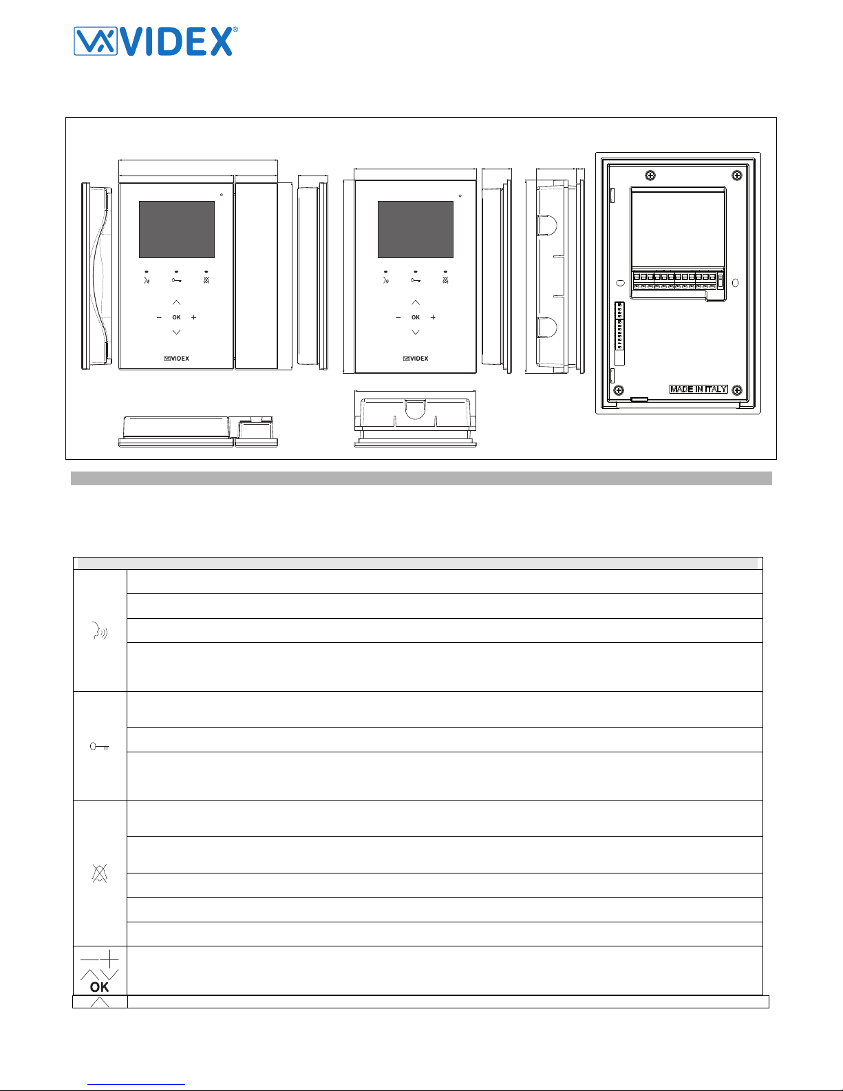
Art.KRV88/KRV86 Kristallo videophones
112 42
155
182
29 120
190
839
189
119
29
KRV88KRV86
AL
LB
LB_AL
DOL
NO
C
+30VAUX
GND
+12Vaux
GND
BUS
BUS
BUS TERMINATION
ON ON
SW3 SW1
Fig.1
DESCRIPTION
Intelligent Hands free video monitor for the VX2300 digital system using 3,5” OSD full colour active matrix LCD monitor, with touch sensitive buttons for
“door open / service” , “answer/camera recall”, “privacy / bus relay” plus 5 navigation menu buttons and 3 LEDs related to the videophone operation. For
the surface version only (Art.KRV76), a handset can also be used in addition to the hands free mode. Additional features include a real time clock, a
temperature sensor and a serial RS232 port for future integration with home automation systems.
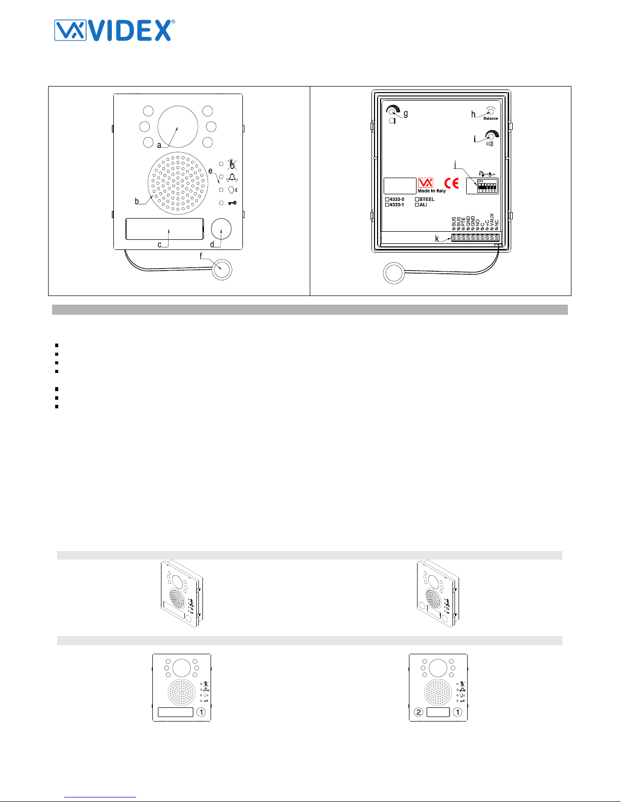
PUSH BUTTONS, LEDS AND CONTROLS (FIG.1)
Answer Button - Press this button during an incoming call to open the speech in duplex mode allowing free speech with the caller in
both directions (The related LED will illuminate).
Camera Recall Button - When the system is in standby, (No calls on the system) operation of this button will open the speech to the
door station. The related LED will illuminate. Press as many time as the ID value of the door panel to connect to.
End Conversation Button - During a conversation, momentary operation of this button will end the call. The LED next to the button will
switch off. The system will automatically switch off when the conversation time expires.
PTT Enable Button - Press and hold this button (more than 1 second), during an incoming call or a conversation in progress, to allow
the user to answer a call from a visitor at the door station in SIMPLEX speech mode (The related LED will flash rapidly): releasing the
button will allow the user to listen to the visitor (The LED will flash slowly). Press and hold the button when you talk to the visitor and
release the button when you listen to the visitor.
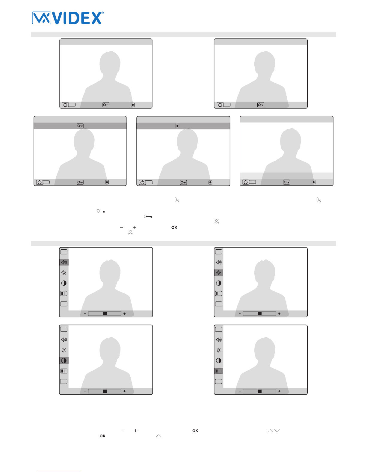
Door Open Button - During a conversation, momentary operation of this button will release the door from where the call originated.
This will be confirmed by an acoustic tone and the key icon on the top of the screen under the date, time & temperature row. If terminal
“DOL” is connected, the “door open” LED next to the button will also be illuminated.
Aux Service Button - During a conversation, keep pressed this button to enable the auxiliary service relay. This will be confirmed by a
message on the display: terminals “C” and “NO” are internally linked until the button is released.
Intercommunicating call button - For an intercommunicating call, when the intercom is in stand-by, press as many times as the ex-
tension number (intercommunication among the apartment units) or address value to call (intercommunication among all the units of
different apartments). For videophones with handset the intercommunication can be hands free or conventional by picking up the hand-
set before calling.
Privacy Button - When the system is in stand-by, press this button to enable the service for the programmed time: the related LED will
illuminate to signal the service enabled. During an incoming call, with the service enabled, the device does not emit any acoustic signal.
The service is disabled when the programmed time expires or pressing again the button.
Programming Menu Button - With the system in stand-by, keep pressed this button until the monitor switches on showing the pro-
gramming menu where you can set date & time, privacy duration, call tone volume, melody and number of rings. Once the menu is en-
abled, proceed with settings by the menu navigation buttons.
Call Reject Button - During an incoming call, press this button to reject the call. The visitor doesn’t receive any warning of the call re-
jected.
Adjustment Menu Button - During a conversation, press this button to enter a programming menu that allows to set speech volume,
picture brightness, contrast and hue. Once the menu is enabled, proceed with settings by the menu navigation buttons.
Bus Relay Button - During a conversation, keep pressed this button until the display shows a yellow band at the bottom side. Select
the BUS Relay to enable by the buttons “Plus” and “Minus” then press OK to enable the relay.
Menu navigation buttons – these buttons to be used during adjustment and programming menus. Via these buttons you can set the
date & time, the melody, the number of rings and the privacy duration and you can adjust the speech and call tone volume and the pic-
ture brightness, contrast and hue. Use top & down arrow to move along settings, plus and minus to alter settings and OK button to
confirm.
Camera switch button - If the door station uses the Art.4303N plus the Art.4330N, pressing this button during a conversation switches

Two Wire Videokit ESVK Series
PrtCode:66550045EN.doc – Pag.7/7 15/02/2013 Rev.1.0
the video signal coming from the camera module to the video signal coming from the camera module input for external camera. During
the conversation, press and keep pressed the button until the camera switches. Repeat the operation to switch back to main camera.
PROGRAMMING
The programming consists of a number of settings that in part are carried out by a specific OSD menu and the rest is carried out by the two dip-switch
banks on the rear side of the videophone:
- Date & Time (OSD);
- Privacy duration from 0 to 20 hours (OSD);
- Melody selection among 9 available (OSD);
- Number of rings from 1 to 9 (OSD);
- Unit address (1..127, switches 1 to 7 of SW1);
- Intercommunication mode (between apartments or within apartment switch 1 of SW3);
- Extension address (1..4, switches 2,3 of SW3);
- Slave mode (switch 4 of SW3);
- Bus Termination (switch to the right of the connection terminals).
Except OSD settings, it is necessary to remove temporary the power supply after making any other programming changes.
PROGRAMMING OSD MENU
EXIT
09:2315/12/11
Fig.1
EXIT
01 . 5h
Fig.1a
EXIT
Fig.1b
EXIT
MELODY 1
Fig.1c
EXIT
RINGS 6
Fig.1d
When the system is in stand-by, keep pressed the button until the monitor switches on showing the screen to the left.
The first programming option is the date & time Fig.1:
change the values by the and buttons;
use buttons and to move between the fields to set (day, month, year, hours and minutes);
confirm the setting by the button or the button when the field minutes is selected. The system goes to next programming step.
The second programming option is the privacy duration Fig.1a (from 0 to 20 hours):
adjust the value by the buttons and (0 = privacy duration unlimited, the service is disabled by pressing again the button );
confirm the value by the or . The system jump to next programming option.
Proceed in the same way for the other programming options: call tone volume (3 level Fig.1b), melody (9 options Fig.1c) and number of rings (for 1
to 9 Fig.1d).
Note
From any of the two OSD menu’s, if the videophone switches off because of the timeout, the controls and the programmings are not stored.
VIDEOMONITOR ADDRESS – SW1.1..7
The table above shows how to set the address of the videophone. Considering that ON = 1 and OFF = 0, multiply each
digit for the relevant decimal weight then sum values obtained to get the address: E.g. as highlighted in the table
OFF,ON,OFF,OFF,ON, OFF,ON in binary is equal to 0100101 then multiplying each digit for the relevant decimal weight
you obtain the address that is 37.
Switches Status Binary Code – Decimal Weight Address
7 6 5 4 3 2 1 64 32 16 8 4 2 1
OFF OFF OFF OFF OFF OFF ON 0 0 0 0 0 0 1 1
OFF OFF OFF OFF OFF ON OFF 0 0 0 0 0 1 0 2
OFF OFF OFF OFF OFF ON ON 0 0 0 0 0 1 1 3
OFF OFF OFF OFF ON OFF OFF 0 0 0 0 1 0 0 4
OFF ON OFF OFF ON OFF ON 0 1 0 0 1 0 1 37
ON ON ON ON ON ON ON 1 1 1 1 1 1 1 127
Note
The maximum number of units allowed is 100 but the address of each unit can be a value between 1 and 127.
SW1.1..7
5
4
3876
ON
2
1
=OFF
=ON ON

Two Wire Videokit ESVK Series
PrtCode:66550045EN.doc – Pag.8/8 15/02/2013 Rev.1.0
INTERCOMMUNICATION MODE – SW3.1
This switch establishes the intercommunication mode: in OFF position (default) intercommunication is between units in the same
apartment (same addresses but different extension); in ON position the intercommunication is between units in different apart-
ments (different addresses).
On installations where there are more than one intercom/videophone in the same apartment and intercommunication between different
apartments is required, only one intercom/videophone may be set with this function (SW3.1=ON, SW3.2=OFF, SW3.3=OFF). The other inter-
com/videophones in the apartment must be set for local intercommunication with extension addresses “2-4” (slaves). From the inter-
com/videophone set for intercommunication with other apartments it will be not possible to intercommunicate within the apartment but slave
extensions 2-4 will be able to intercommunicate with each other.
EXTENSION NO – SW3.2..3
If the intercommunication between apartments is enabled (switch 1 of SW3 = ON) leave these two switches in default position (both to OFF). Otherwise,
if the intercommunication is between the same apartment (switch 1 of SW3 = OFF), set the extension addresses starting always from 1. During the ex-
ternal call, all video monitors in the same flat will ring but the video will be shown only from the videmononitor with extension address 1.
2 3 Extension No.
OFF OFF 1 (default, master)
ON OFF 2 (slave)
OFF ON 3 (slave)
ON ON 4 (slave)
4
3
ON
2
1
=OFF
=ON ON
SW3.2..3
SLAVE MODE - SW3.4
This set up concerns the answering mode of the video monitor when there is more than one unit (max 4) in the same apartment.
OFF (default) = during a call, only the video monitor with extension 1 (master) will show the video. ON = the video monitor will be
switched on independently of the extension address: in this case the video monitor must be supplied locally using a power sup-
ply Art.2321 and connecting respectively BUS+ to terminal 14 and BUS- to terminal 11 of the pcb connection board provided
with the Art.5980 (the local power supply is required for each black & white slave videophone or starting from the third slave vid-
eophone when are used all colour videophones). If you set ON this switch for one slave videophone, you must set ON the same switch also for
the relevant master videophone.
BUS LINE TERMINATION
The factory pre-set is termination enabled. In case of more units (intercoms, videophones or video monitors) in a parallel connection (bus wires are con-
nected to the terminals of the first unit then from this to the second and so on up to 4 units max) Termination must be enabled only for the last unit in the
chain while on all other units must be disabled. In case of units of different type, videophones, video monitor, hands free or standard intercoms etc. re-
mains fixed the rule that the bus termination must be enabled only on the last unit in order of connection.
Termination enabled (factory pre-set). Termination disabled.
OPERATION
RECEIVING A CALL
15/12/11 14.5°C 09:23
MENU
PTT
Fig.2 Fig.2a
15/12/11 14.5°C 09:23
MENU
PTT
Fig.2b Fig.2c
During a call the display switches on showing the screen on figure 2:
To answer in hands free mode press the button Fig.1a (or pick up the handset on model KRV76);
To open the door without speech to the visitor press the button Fig1.b;
To reject the call without informing the visitor press the button Fig1c
4
3
ON
2
1
=OFF
=ON ON
SW3.4
4
3
ON
2
1
=OFF
=ON ON
SW3.1

Two Wire Videokit ESVK Series
PrtCode:66550045EN.doc – Pag.9/9 15/02/2013 Rev.1.0
DURING THE CONVERSATION
15/12/11 14.5°C 09:23
MENU
PTT
15/12/11 14.5°C 09:23
PTT
Fig.3 Fig.3a
15/12/11 14.5°C 09:23
MENU
PTT
15/12/11 14.5°C 09:23
MENU
PTT
SRV
15/12/11 14.5°C 09:23
MENU
PTT
SERV. - 1 + OK?
Fig.3b Fig.3c Fig.3d
During the conversation Fig.3:
To switch from hands free to push to talk mode, keep pressed the until the related LED starts to flash slowly Fig.3a. Keep pressed the button
to talk to the visitor (the LED flashes quickly) and release the button (the LED flashes slowly) to listen the visitor;
To open the door press the button Fig.3b;
To enable the secondary service keep pressed the button until the activation signals (call tone plus message) are received Fig.3c;
To enable the BUS relay Art.2305 (if connected on the pass) keep pressed the button until the display shows the picture in figure 3d then select
the BUS relay to enable by the buttons and and confirm with button.
To enter into programming menu press the button Fig.4.
ADJUSTMENTS MENU
OSD
EXIT
OSD
EXIT
Fig.4 Fig.4a
OSD
EXIT
OSD
EXIT
Fig.4b Fig.4c
In the programming menu you can set:
The speech volume (8 levels Fig.4);
The picture brightness (8 levels Fig.4a);
The picture contrast (8 levels Fig.4b);
The picture hue (8 levels Fig.4c);
Adjust the selected option using the buttons and then confirm by the button to move to next option or use the buttons to navigate the op-
tions. With “EXIT” selected, press to exit from the menu or do adjust other settings.

Two Wire Videokit ESVK Series
PrtCode:66550045EN.doc – Pag.10/10 15/02/2013 Rev.1.0
VIDEOMONITOR WALL MOUNTING INSTRUCTIONS
135cm
Fig.1
135cm
Fig.1a
Fig.1b
Fig.2
Fig.2a
Fig.3 Fig.3a
Fig.4
Fig.4a Fig.4b
FLUSH MOUNT KRISTALLO VIDEOPHONE
1. Protect the holes to fix the videophone to the flush mounting box then embed the flush mounting box in line with the wall in vertical position at
135cm height from the floor as shown in figure 1.
2. As shown in figure 2, connect the wires using a flat screw driver then setup the dip-switches as per provided connection diagram or instruction
sheet.
3. As shown in figure 3, once the wires are connected, fix the videophone to the flush mounting box using a Phillips screwdriver and the two screws
provided.
4. Once the videophone is fixed to the flush mounting box, place the front plate against the videophone by inserting the hooks in the corresponding
openings and hook the plate by pushing it down as shown in figure 4.
5. Test the system for correct operation.
SURFACE MOUNT KRISTALLO VIDEOPHONE
1. As shown in figure 1a, place the videophone against the wall at 135cm height from the floor and mark the fixing holes. Make the holes (5mm diam-
eter) and insert the provided wall plugs as shown in figure 1b.
2. As shown in figure 2a, connect the wires using a flat screw driver then setup the dip-switches as per provided connection diagram or instruction
sheet.
3. As shown in figure 3a, once the wires are connected, fix the videophone to the wall using a Phillips screwdriver and the two screws provided.
4. Once the videophone is fixed to the wall, place the front plate against the videophone by inserting the hooks in the corresponding openings and
hook the plate by pushing it down as shown in figure 4a and hang the handset as shown in figure 4b.
5. Test the system for correct operation.

Two Wire Videokit ESVK Series
PrtCode:66550045EN.doc – Pag.11/11 15/02/2013 Rev.1.0
CONNECTION
SIGNAL ON CONNECTION TERMINALS
AL Alarm input (not implemented yet)
LB Local bell input (active low)
LB_AL Ground output for use in combination with “AL” & “LB” active low inputs
DOL Auxiliary LED power supply input (+12Vdc – normally used as “DOOR OPEN” LED)
C Dry contacts relay common contact (during a conversation, keep pressed the button for more than 3 seconds to enable the in-
ternal link between terminals “C” and “NO” – the link remains until the button is released) Max 50Vdc @ 100mA.
NO Dry contacts relay normally open contact (during a conversation, keep pressed the button for more than 3 seconds to enable the
internal link between terminals “C” and “NO” – the link remains until the button is released) Max 50Vdc @ 100mA
+30Vaux Auxiliary 30Vdc power supply input (to be used when the switch 4 of SW3 is set to ON when more videophone have the same ad-
dress and must be switched ON at the same time).
GND 30Vdc power supply ground
+12Vaux Auxiliary 12Vdc power supply input for memory board version (not implemented yet)
GND 12Vdc power supply ground
BUS Bus input terminal
Note
The KRV88 and KRV86 videophones must be used in combination with Art.318 passive video distributor.
RESTORING FACTORY PRESET
To restore factory preset, proceed as follows:
Cut off power supply;
Make a short between “LB” and “GND” terminals;
Restore power supply and wait until LED blinks twice before remove the short.
The unit parameters are restored to factory preset.
SPECIFICATION
Housing/Mounting 5000 Series Videophones / mounting plate plus connection board
Push buttons Yes, 6
Programming Yes, carried out by the dip-switches located on the rear of the videophone
Controls Loudspeake and call tone volume, brightness and hue
Power Supply Supplied by the BUS line
Working Temperature -10 +50 ºC
CUSTOMER SUPPORT INFORMATION
All Countries Customers UK Customers
VIDEX Electronics S.p.A.
Tel.+39 0734 631669
Fax +39 0734 632475
VIDEX Security LTD
www.videx-security.com
Tech Line 0191 224 3174
Fax 0191 224 1559
The product is CE marked demonstrating its conformity and is for distribution within all
member states of the EU with no restrictions.
This product follows the provisions of the European Directives
89/336/EEC & 92/31/EEC (EMC),
73/23/EEC (LVD) and 93/68/EEC (CE marking).
Il prodotto è marchiato CE a dimostrazione della sua conformità e può essere distribui-
to liberamente all’interno dei paesi membri dell’unione europea EU.
Questo prodotto è conforme alle direttive Europee
89/336/EEC & 92/31/EEC (EMC),
73/23/EEC (LVD) e 93/68/EEC (Marcatura CE).

Two Wire Videokit ESVK Series
PrtCode:66550045EN.doc – Pag.12/12 15/02/2013 Rev.1.0
Art.125 Call expansion module
Fig.1
DESCRIPTION
This module must be used in combination with speaker units Art.4333 with firmware release 2.0 or higher. The module, in combination with standard
4000 series button expansion modules (Art.4842, 4843, 4844 and 4845), allows to add up to 5 call buttons to the call buttons built-in the speaker unit to
reach a maximum of 7 call buttons. To supply the LED of the button expansion modules make the connection as shown in figure 1.
UNIT SPECIFICATION
Housing/Mounting 5 resistors module / fix to button expansion module
Push Buttons N/A
Programming N/A
Controls N/A
Power Supply N/A
Working Temperature -10 +50ºC
CUSTOMER SUPPORT INFORMATION
All Countries Customers UK Customers
VIDEX Electronics S.p.A.
Tel.+39 0734 631669
Fax +39 0734 632475
VIDEX Security LTD
www.videx-security.com
Tech Line 0191 224 3174
Fax 0191 224 1559
The product is CE marked demonstrating its conformity and is for distribution within all
member states of the EU with no restrictions.
This product follows the provisions of the European Directives
89/336/EEC & 92/31/EEC (EMC),
73/23/EEC (LVD) and 93/68/EEC (CE marking).
Il prodotto è marchiato CE a dimostrazione della sua conformità e può essere distribui-
to liberamente all’interno dei paesi membri dell’unione europea EU.
Questo prodotto è conforme alle direttive Europee
89/336/EEC & 92/31/EEC (EMC),
73/23/EEC (LVD) e 93/68/EEC (Marcatura CE).

Two Wire Videokit ESVK Series
PrtCode:66550045EN.doc – Pag.13/13 15/02/2013 Rev.1.0
Art.318 Two way passive distribution box
BUS
IN
BUS
OUT
BUS
OUT1
BUS
OUT2
Art.318
Close
Open
BL
Fig.1 Fig.2
DESCRIPTION
The unit distributes the bus signal to 2 outputs linked to videophones or intercoms. It is a passive distributor, so there is no possibility to adjust the video
amplification. The device is suitable for small systems with a maximum distance between door panel and the last monitor of 70 metres.
CONNECTION TERMINALS AND JUMPERS
Terminal/Jumper Description
BUS IN Bus input terminals
BUS OUT Bus output terminals (to next distrbutor)
BUS OUT 1 Videophone/Intercom bus output 1
BUS OUT 2 Videophone/Intercom bus output 2
BL Close/Open bus output jumper. If the distributor is the last move to close otherwise leave open.
SPECIFICATION
Housing/Mounting Plastic box 50x60x20mm / direct wall mounting
Push Buttons N/A
Programming N/A
Controls N/A
Power Supply Supplied by the BUS line
Working Temperature -10 +50ºC
CUSTOMER SUPPORT INFORMATION
All Countries Customers UK Customers
VIDEX Electronics S.p.A.
Tel.+39 0734 631669
Fax +39 0734 632475
VIDEX Security LTD
www.videx-security.com
Tech Line 0191 224 3174
Fax 0191 224 1559
The product is CE marked demonstrating its conformity and is for distribution within all
member states of the EU with no restrictions.
This product follows the provisions of the European Directives
89/336/EEC & 92/31/EEC (EMC),
73/23/EEC (LVD) and 93/68/EEC (CE marking).
Il prodotto è marchiato CE a dimostrazione della sua conformità e può essere distribui-
to liberamente all’interno dei paesi membri dell’unione europea EU.
Questo prodotto è conforme alle direttive Europee
89/336/EEC & 92/31/EEC (EMC),
73/23/EEC (LVD) e 93/68/EEC (Marcatura CE).

Two Wire Videokit ESVK Series
PrtCode:66550045EN.doc – Pag.14/14 15/02/2013 Rev.1.0
Art.2301N Entrances exchanger for VX2300 digital systems
Fig.1 Fig.2
DESCRIPTION
This unit is required for systems with 2 or more entrances (4 maximum). The Art.2301N has 4 inputs (IN1..IN4) each with adjustable amplification (“L” =
low, “M” = medium and “H” = high) to compensate for different door station distances. The AUX input enables a second 2301N device to be connected
to expand the system up to 8 entrances. When connecting 2x2301N the polarity of the bus between the Art.2301N's must be observed. When connect-
ing 2x2301N's the BUS output of the first exchanger must be linked to the AUX input of the second exchanger and then onto the apartments. The polari-
ties are not relevant if there is only one 2301N.
The power supply inputs are PS1and PS2. The Art.2321/P with its jumper set to V2 should be used. For systems with up to 4 entrances and 50 video-
phones only one power supply is required connected to PS1. For larger systems connect a power supply to each of the two inputs (PS1 & PS2).
When 2x2301N, the 2x2321/P power supplies only connect to the 2301N at which the AUX connection is used. (The one supplying the apart-
ments).
CONNECTION TERMINALS AND JUMPERS
Terminal/Jumper Description
BUS- BUS Output (observe the polarities only when linked to the AUX input of a second 2301N)
BUS+
AUX- Auxiliary BUS input to carry out systems up to 8 entrances linking together two 2301N (observe the polarities when connect-
ing the BUS output of the first exchanger to the AUX of the second BUS- with AUX- and BUS+ with AUX+)
AUX+
IN1 Door station input 1 (the signal may be amplified by the relative jumper – L=Low, M=Medium and H=High)
IN2 Door station input 2 (the signal may be amplified by the relative jumper – L=Low, M=Medium and H=High)
IN3 Door station input 3 (the signal may be amplified by the relative jumper – L=Low, M=Medium and H=High)
IN4 Door station input 4 (the signal may be amplified by the relative jumper – L=Low, M=Medium and H=High)
PS1 Power Supply input 1 (use Art.2321/P set to V2 voltage level)
PS2 Power Suppy input 2 (use Art.2321/P set to V2 voltage level)
SPECIFICATION
Housing/Mounting 9 Module A Type DIN box / DIN Bar or directly to the wall
Push Buttons N/A
Programming N/A
Controls Signal amplification on 3 levels for each bus input
Power Supply From specific power supply or from the bus
Working Temperature -10 +50ºC
CUSTOMER SUPPORT INFORMATION
All Countries Customers UK Customers
VIDEX Electronics S.p.A.
Tel.+39 0734 631669
Fax +39 0734 632475
VIDEX Security LTD
www.videx-security.com
Tech Line 0191 224 3174
Fax 0191 224 1559
The product is CE marked demonstrating its conformity and is for distribution within all
member states of the EU with no restrictions.
This product follows the provisions of the European Directives
89/336/EEC & 92/31/EEC (EMC),
73/23/EEC (LVD) and 93/68/EEC (CE marking).
Il prodotto è marchiato CE a dimostrazione della sua conformità e può essere distribui-
to liberamente all’interno dei paesi membri dell’unione europea EU.
Questo prodotto è conforme alle direttive Europee
89/336/EEC & 92/31/EEC (EMC),
73/23/EEC (LVD) e 93/68/EEC (Marcatura CE).

Two Wire Videokit ESVK Series
PrtCode:66550045EN.doc – Pag.15/15 15/02/2013 Rev.1.0
Art.2305 Extension Relay for VX2300 digital systems
Fig.1 Fig.2
DESCRIPTION
This unit can be connected directly to the bus and has two operating modes: general purpose extension relay and apartment extension relay for addi-
tional sounders. As general purpose extension relay, the built-in relays are controlled by the relevant button of the intercom or videophone while as ex-
tension sounder relay, relay one will operate on each ring and relay two will operate for the duration of the call.
CONNECTION TERMINALS & DIP-SWITCHES
Terminal/Jumper Description
BUS Input/Output bus connection terminals
C2 Relay 2 common contact
NO2 Relay 2 normally open contact
NC2 Relay 2 normally closed contact
C1 Relay 1 common contact
NO1 Relay 1 normally open contact
NC1 Relay 1 normally closed contact
DIP-SW 8 way dip-switch to set the relay operating mode
PROGRAMMING
The operating mode is set by switch 8 as shown below. Note: After making changes to the dip-switch settings it is necessary to disconnect it from the
bus (or power the system down) and then reconnect before the changes will take affect.
GENERAL PURPOSE EXTENSION RELAY – SWITCH 8 = OFF
When the unit is set as general purpose extension relay, switches 1 to 6 are used to set the relays addresses and activation times.
Switches Relay 1,2
Addresses
Switches Relay 1
Time
Switches Relay 2
Time
1 2 3 4 5 6
OFF OFF 1,2 OFF OFF 2 seconds OFF OFF 2 seconds
ON OFF 3,4 ON OFF 4 seconds ON OFF 4 seconds
OFF ON 5,6 OFF ON 16 seconds OFF ON 16 seconds
ON ON 7,8 ON ON 32 seconds ON ON 32 seconds
Switch 7 is not used.
For example if switch 1 is set to ON and switch 2 is set to OFF (addresses 3 & 4), pressing the “dot” button on the intercom (or “double dot” on the vide-
ophone) 3 times will operate relay one while pressing 4 times will operate relay two.
EXTENSION SOUNDER RELAY – SWITCH 8 = ON
When the unit is set in this mode, switches from 1 to 7 (8 is not used but set to on) are used to set the address of the unit: the address of the unit is set
to the same address as the videophone or intercom it that apartment (refer to intercom/videophone SW1 settings).
When the apartment is called, relay 1 will operate 4 times (once for each ring) while relay 2 will energise for the duration of the call (Approx. 60 sec-
onds). The relays revert to the de-energised state if the call is cancelled or the user ends the call.
SPECIFICATION
Housing/Mounting 5 Module A Type DIN box / DIN bar or directly to the wall
Push Buttons N/A
Programming Yes, carried out by the 8 way dip-switch
Controls N/A
Power Supply from the bus
Working Temperature -10 +50ºC
Dry contacts relay Max 24Vac/dc 5A
CUSTOMER SUPPORT INFORMATION
All Countries Customers UK Customers
VIDEX Electronics S.p.A.
Tel.+39 0734 631669
Fax +39 0734 632475
VIDEX Security LTD
www.videx-security.com
Tech Line 0191 224 3174
Fax 0191 224 1559
The product is CE marked demonstrating its conformity and is for distribution within all
member states of the EU with no restrictions.
This product follows the provisions of the European Directives
89/336/EEC & 92/31/EEC (EMC),
73/23/EEC (LVD) and 93/68/EEC (CE marking).
Il prodotto è marchiato CE a dimostrazione della sua conformità e può essere distribui-
to liberamente all’interno dei paesi membri dell’unione europea EU.
Questo prodotto è conforme alle direttive Europee
89/336/EEC & 92/31/EEC (EMC),
73/23/EEC (LVD) e 93/68/EEC (Marcatura CE).

Two Wire Videokit ESVK Series
PrtCode:66550045EN.doc – Pag.16/16 15/02/2013 Rev.1.0
Art.2380 Interface “2 Wire” to “4+1” audio system
Fig.1 Fig.2
DESCRIPTION
Interface to connect 4+ 1 audio devices to the VX2300 “2 Wire” Bus (For example the Art.380 telephone interface or the Art.275/2W PABX interface)
Using the items listed above (380, 275/2W) it is possible to use a conventional household telephone as a standard intercom.
The operating mode of the telephone depends on the connected device and on the connections made, refer to the instructions of the Art.380 or Art275.
DIP-SWITCHES AND JUMPERS (FIG.1)
SW1 Switches from 1 to 7 are used for unit address (from 1 to 127 binary coded). Last switch (8) is not used
SW2 Switches 1,2 and 3 are used to set privacy duration time. Switch 4 is used to set the “Priv” signal operating mode
SW3 Switches 1,2 and 3 are used for intercommunication settings. Switch 4 is not used
S1 Impedance terminator. The jumper must be normally closed. When more videophones/intercoms are connected in parallel (from a pe-
ripheral to another and so on until the last) the jumper must be open for all the intercoms except for the last following the order of connec-
tion.
PROGRAMMING
After each programming operation carried out through dip-switches or jumpers it is necessary to temporary disconnect the device from the BUS or from
the power supply if locally powered.
SW1 – DEVICE ADDRESS
Switches Status Binary Code – Decimal Value Decimal
Code
7 6 5 4 3 2 1 64 32 16 8 4 2 1
OFF OFF OFF OFF OFF OFF ON 0 0 0 0 0 0 1 1
OFF OFF OFF OFF OFF ON OFF 0 0 0 0 0 1 0 2
OFF OFF OFF OFF OFF ON ON 0 0 0 0 0 1 1 3
OFF OFF OFF OFF ON OFF OFF 0 0 0 0 1 0 0 4
OFF ON OFF OFF ON OFF ON 0 1 0 0 1 0 1 37
ON ON OFF OFF OFF ON ON 1 1 0 0 0 1 1 99
The table above shows how to set the address of the device. Considering that ON = 1 and OFF = 0, multiply each digit for the relevant decimal weight
then sum the values obtained to get the address: E.g. as highlighted in the table OFF,ON,OFF,OFF,ON, OFF,ON in binary is equal to 0100101 then
multiplying each digit for the relevant decimal weight you obtain the address that is 37.
Note
The maximum number of units allowed is 100 but the address of each unit can be a value between 1 and 127.
SW2 – PRIVACY DURATION TIME
Switches Status Privacy Mode
(switch 1)
Privacy Duration
(switches 2,3)
1 2 3 4
OFF
OFF OFF
The privacy duration time is set by switches 2 and 3. When enabled the privacy ser-
vice will be disabled when the set time expires or the switch is moved back to off. 15 minutes
ON OFF 1 hour
OFF ON 4 hours
ON ON 8 hours
ON No privacy time expiration: the privacy service is enabled or disabled only by the
slide switch.
ON
The “Priv” terminal works as an open collector output to signal the status of the pri-
vacy service. When the service is enabled the “Priv” output shorts to ground.
OFF
This mode must be set when the Art.2380 is connected in parallel (with the
same address) to one or more intercoms/videophones. Make a link between
terminals “Priv” and “2”.

Two Wire Videokit ESVK Series
PrtCode:66550045EN.doc – Pag.17/17 15/02/2013 Rev.1.0
SW3 – INTERCOMMUNICATION SETTINGS
Switches Status Intercommunication Mode
(switch 1)
Unit
Extension
(switches 2,3)
1 2 3 4
OFF
OFF OFF
Intercommunication allowed between units (same unit address) inside the same flat.
To call an extension pick up the handset then press the “door open” button as many
times as the extension value (Eg. extension 2 two times, 3 three times etc). Each
intercom/videophone in the same apartment must have a different extension
address, the master address must always be set except when one of the inter-
com/videophone is set for apartment intercommunication (i.e. in a 3 inter-
com/videophone installation, one of the intercom/videophone must have the
extension address 1 while the others must have different addresses)
1 (master)
ON OFF 2 (slave)
OFF ON 3 (slave)
ON ON 4 (slave)
ON OFF OFF
Intercommunication allowed between videophones (different apartment). To call an
extension pick up the handset then press the “door open” button as many times as
the address value (Eg. extension 10 ten times, 12 twelve times etc)
OFF The operation is not altered.
ON
The Art.2380 delays of 20 seconds the call toward the “4+1” interface to which is connected the
Art.275/2W or Art.380. During a call, If the Art.2380 is in parallel connection with an intercom or a video-
phone, answering from the intercom/videophone stops the call toward the “4+1” interface.
NOTE: Extension 1 is mandatory. On systems with more than one device in an apartment, each device must have a unique extension ID.
On installations where there are more than one intercom/videophone in the same apartment and intercommunication between different
apartments is required, only one intercom/videophone may be set with this function (SW3.1=ON, SW3.2=OFF, SW3.3=OFF). The other inter-
com/videophones in the apartment must be set for local intercommunication with extension addresses “2-4” (slaves). From the inter-
com/videophone set for intercommunication with other apartments it will be not possible to intercommunicate within the apartment but slave
extensions 2-4 will be able to intercommunicate with each other.
SIGNALS ON CONNECTION TERMINALS
Signal Description
BUS BUS connection terminals
BUS
2 Speech line in
1 Speech line out
3 Speech ground
4 Call output
GND Ground
5 Active low input “door open” command
A2in Auxiliary active low input 2. When active (0V) switches the status of privacy service.
A1in Auxiliary active low input 1. When active (0V) the relay with address 1 of the Art.2305 if installed in the system will activate.
+12Vout +12Vdc Output
Priv
With SW2.4 = OFF, it works as an open collector output that signals the privacy service status. Internal link to ground when the privacy
service is active.
With SW2.5 = ON, required setting when the Art.2380 is in a parallel (same address) connection with other devices it must be linked to
terminal two.
SPECIFICATION
Housing/Mounting 9 Module A Type DIN box
Push Buttons N/A
Programming Yes, carried out through dip-switches
Controls N/A
Power Supply Supplied from the BUS
Working Temperature -10 +50ºC
CUSTOMER SUPPORT INFORMATION
All Countries Customers UK Customers
VIDEX Electronics S.p.A.
Tel.+39 0734 631669
Fax +39 0734 632475
VIDEX Security LTD
www.videx-security.com
Tech Line 0191 224 3174
Fax 0191 224 1559
The product is CE marked demonstrating its conformity and is for distribution within all
member states of the EU with no restrictions.
This product follows the provisions of the European Directives
89/336/EEC & 92/31/EEC (EMC),
73/23/EEC (LVD) and 93/68/EEC (CE marking).
Il prodotto è marchiato CE a dimostrazione della sua conformità e può essere distribui-
to liberamente all’interno dei paesi membri dell’unione europea EU.
Questo prodotto è conforme alle direttive Europee
89/336/EEC & 92/31/EEC (EMC),
73/23/EEC (LVD) e 93/68/EEC (Marcatura CE).

Two Wire Videokit ESVK Series
PrtCode:66550045EN.doc – Pag.18/18 15/02/2013 Rev.1.0
Art.2321-2321/P Power supplies for VX2300
65
157,5
105
Art.2321
0V
230V
+
_
BUS
Fig.1 Fig.2
DESCRIPTION
These two units are specific power supplies for VX2300 digital system. The 2321 can be used for systems with 1 entrance up to 20 users while the
2321/P is for systems with more than 1 entrance and up to 100 users.
CONNECTION TERMINALS AND JUMPERS
Terminal/Jumper Description
0 Mains input
~230V
BUS + BUS terminals
BUS -
BUS + BUS terminals (only Art.2321/P)
BUS -
V1 Jumper to adjust the output voltage (only Art.2321/P). V1=Low, V2=Medium, V3=Maximum. Set to maximum (V3) when the
unit is used together with 2301N, otherwise leave in a low or medium position
V2
V3
CONNECTION TO MAINS AND POWER SUPPLY MOUNTING INSTRACTIONS
The system must be installed according to national rules in force, in particular we recommend to:
- Connect the system to the mains through an all-pole circuit breaker which shall have contact separation of at least 3mm in each pole and shall discon-
nect all poles simultaneously;
- The all-pole circuit breaker shall be placed for easy access and the switch shall remain readily operable.
POWER SUPPLY INSTALLATION
- Remove the terminal side covers by unscrewing the retaining screws;
- Fix the power supply to a DIN bar or directly to the wall using two expansion type screws;
- Switch off the mains using the circuit breaker mentioned above and then make the connections as shown on the installation diagrams;
- Check the connections and secure the wires into the terminals;
- Replace the terminal covers and fix them using the relevant screws;
- When all connections are made, restore the mains.
SPECIFICATION
Housing/Mounting 9 Module A Type DIN box (Art.2321) – 15 Module A Type DIN box (Art.2321/P) / DIN Bar or directly to the wall
Push Buttons N/A
Programming N/A
Controls Voltage amplification (3 levels)
Power Supply 230Vac
Working Temperature -10 +50ºC
CUSTOMER SUPPORT INFORMATION
All Countries Customers UK Customers
VIDEX Electronics S.p.A.
Tel.+39 0734 631669
Fax +39 0734 632475
VIDEX Security LTD
www.videx-security.com
Tech Line 0191 224 3174
Fax 0191 224 1559
The product is CE marked demonstrating its conformity and is for distribution within all
member states of the EU with no restrictions.
This product follows the provisions of the European Directives
89/336/EEC & 92/31/EEC (EMC),
73/23/EEC (LVD) and 93/68/EEC (CE marking).
Il prodotto è marchiato CE a dimostrazione della sua conformità e può essere distribui-
to liberamente all’interno dei paesi membri dell’unione europea EU.
Questo prodotto è conforme alle direttive Europee
89/336/EEC & 92/31/EEC (EMC),
73/23/EEC (LVD) e 93/68/EEC (Marcatura CE).

Two Wire Videokit ESVK Series
PrtCode:66550045EN.doc – Pag.19/19 15/02/2013 Rev.1.0
Art.2322
Power supply converter from BUS line to 12 Vdc
BUS
+
12V
-
Art.2322
Fig.1 Fig.2
DESCRIPTION
When this unit is connected to the BUS line it generates a +12Vdc – 100mA power source. This unit can be used to supply peripherals such as the
Art.4800 without the need for an additional power supply. Please note: The peripherals must not require more than 100mA.
CONNECTION TERMINALS
Terminal/Jumper Description
BUS BUS line inputs
BUS
12V+ 12Vdc – 100mA output
12V- (0V)
SPECIFICATION
Housing/Mounting Plastic box 50x60x20mm / direct wall mounting
Push Buttons N/A
Programming N/A
Controls N/A
Power Supply Supplied by the BUS line
Working Temperature -10 +50ºC
CUSTOMER SUPPORT INFORMATION
All Countries Customers UK Customers
VIDEX Electronics S.p.A.
Tel.+39 0734 631669
Fax +39 0734 632475
VIDEX Security LTD
www.videx-security.com
Tech Line 0191 224 3174
Fax 0191 224 1559
The product is CE marked demonstrating its conformity and is for distribution within all
member states of the EU with no restrictions.
This product follows the provisions of the European Directives
89/336/EEC & 92/31/EEC (EMC),
73/23/EEC (LVD) and 93/68/EEC (CE marking).
Il prodotto è marchiato CE a dimostrazione della sua conformità e può essere distribui-
to liberamente all’interno dei paesi membri dell’unione europea EU.
Questo prodotto è conforme alle direttive Europee
89/336/EEC & 92/31/EEC (EMC),
73/23/EEC (LVD) e 93/68/EEC (Marcatura CE).

Two Wire Videokit ESVK Series
PrtCode:66550045EN.doc – Pag.20/20 15/02/2013 Rev.1.0
General Directions for Installation
CABLE TYPES AND CROSS SECTIONAL AREAS
The VX2300 digital system can use several types of cables but depending on their specification will allow different distances up 400 meters maximum.
We do not recommend the use of shielded cables because of the high eddy capacitance. It is also not advised to double up on cables as this will also
increase the capacitance. The following table specifies values of resistance, capacitance and maximum distances achievable for several types of cables
(capacitance and resistance values are referring to 100 metres of cable).
Cable Type** Section (mm
2
) Resistance (Ohm) Capacity (nF) *Maximum Distance (meters)
VIDEX CM2 0.50 3.2 8 200m
CAT5 UTP/CW1308 0.22 8 4.9 70m
Std Telephone Cable 0.28 6.5 5.5 100m
Two wire 0.8 / 1 2 6.5 70m
* Between the power supply and the furthest door station or between the power supply and the furthest videophone.
** To carry out the installation, it is compulsory that the video intercom system cables are not carried along with mains or other high power supply ca-
bles because if they are directly exposed to electromagnetic interference this may cause noises on audio/video and lost of functionality over digita
l
communications. In case it is not possible to carry the cables as requested, or in case it necessary to use the existing cables, we suggest to evaluate
the feasibility of the installation before.
In case of use of cables not in conformity with above specification it is possible to experience deterioration of digital and video signals. We suggest to
use twisted cables with maximum resistance of 10 Ohm/100m for each wire (between the farthest door station and the farthest videophone) and maxi-
mum capacitance of 40nF (this value must be computed considering all the cables used in the system; the capacitance/metres value is normally speci-
fied on the cable package or directly on the cable).
BUS DEVICES SETUP AND VIDEO DISTRIBUTION
Any device on the system (door station, intercom, videophone, relay etc.) for which the programming is carried out through one or more dip-switches,
to store the new setup, must be disconnected from the power supply for 1 minute at least.
When you have more than one device in the same apartment, all the devices must be connected to the same video distributor (Art.317): this means
that you cannot use two video distributors Art.318 for one apartment where you have 4 videophones/intercoms.
Once the system is wired, proceed to test the system. If it is required to adjust the level of the video signal, you can operate the devices on the system
where it is possible to make this adjustment like entrances exchanger, block exchanger, bus booster and video distributors.
HOW TO CONNECT LOCAL POWER SUPPLY
The drawing below shows how to connect a local power supply when required (i.e. when you have 4 videophones with the same address that must be
switched on at the same time). In both cases switch 4 of SW3 must be set to the ON position.
NOTE ! OBSERVE CONNECTION POLARITIES AS SHOWN IN THE DIAGRAM BELOW.
This manual suits for next models
10
Table of contents
Other Videx Telephone manuals

Videx
Videx SMVK1 User manual

Videx
Videx 3000 Series User manual

Videx
Videx 3000 Series User manual

Videx
Videx 6778 VX2200 User manual

Videx
Videx 4KC Series User manual

Videx
Videx 3676 User manual

Videx
Videx Kristallo KRV7 Series User manual

Videx
Videx 3000 Series User manual

Videx
Videx 6200 Series User manual

Videx
Videx 6778 User manual

Videx
Videx 3000 Series User manual

Videx
Videx 6300 Series User manual

Videx
Videx 3412 User manual

Videx
Videx 6788 User manual

Videx
Videx 6300 Series User manual

Videx
Videx 3000 Series User manual

Videx
Videx 280N1 User manual

Videx
Videx 3000 Series User manual

Videx
Videx 6200 Series User manual

Videx
Videx 6200 Series User manual