Lesen Sie vor der ersten Benutzung des Produktes bzw. dessen Einbau diese Bedienungsan-
leitung aufmerksam durch.
Das Produkt richtig verwenden
Dieser Decoder ist bestimmt
- zum Einbau in eine Modelleisenbahnanlage zum Schalten von Dauerströmen für Lampen,
Motoren usw. von maximal 2Apro Ausgang bei einer Betriebsspannung von max. 24 V.
- zum Betrieb innerhalb eines DCC-(NMRA-), Märklin-(Motorola-) oder Multiprotokoll-Digital-
systems.
Jeder darüber hinausgehende Gebrauch gilt als nicht bestimmungsgemäß. Für hieraus resul-
tierende Schäden haftet der Hersteller nicht; das Risiko hierfür trägt allein der Benutzer.
2
Wichtige Hinweise!
Important information
Before using this product for the first time read this user guide attentively.
Using the product for its correct purpose
This decoder is intended for use
- to install it in a model railway layout to switch continuous current for lamps, motors etc. with a
maximum current of 2 Afor each output and a maximum voltage of 24 V.
- within a DCC (NMRA), Märklin (Motorola) or multi-protocol model railway digital system.
Using the product for any other purpose is not approved and is considered incorrect. The
manufacturer can not be held responsible for any damages resulting from the improper use of
this product; liability in such a case rests with the user.
Einleitung
Introduction
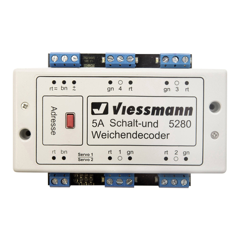
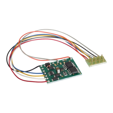
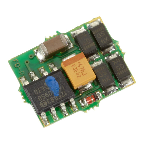
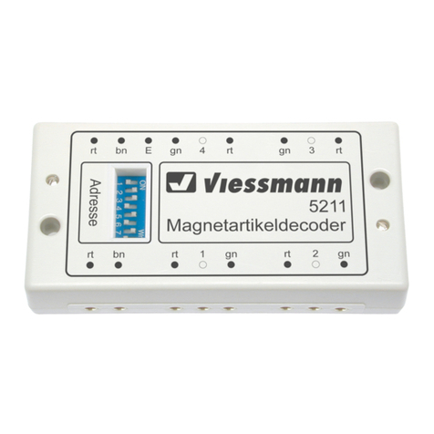
Der DCC-Schaltdecoder 5209 von besitzt 4 separat ansteuerbare Umschalter, wel-
che zum Schalten von z.B. Modell-Leuchten, Lichtsignalen oder Motoren eingesetzt werden
können. Auch Gleisabschnitte können hiermit stromlos geschaltet werden, z.B. zur Realisie-
rung von Blockabschnitten.
viessmann
Der DCC-Schaltdecoder 5209 versteht sowohl das DCC- (NMRA-) als auch das Märklin-Moto-
rola-Datenformat und kann somit vom Märklin Digital~ - System, dem alten Märklin Digital= -
System, Arnold digital neu alt (jeweils mit dem Keyboard, Switchboard oder auch dem
Interface), Lenz DIGITAL plus, Digitrax, der Intellibox von Uhlenbrock sowie allen anderen
DCC- und Märklin-Motorola-kompatiblen Digitalsystemen angesteuert werden .
Hierzu muß der Decoder auf eine Adresse eingestellt werden, welche ihn 4 aufeinanderfol-
genden Tastenpaaren eines Switch- oder Keyboards oder der Intellibox zuordnet, siehe folgen-
denAbschnitt “Adreßeinstellung”.
und
The DCC switching decoder 5209 has got four separately switchable SPDT swit-
ches which can be used for example to switch model lamps, colour light signals or motors. They
can also be used for switching the current of insulated rail sections (e.g. for a blocking system).
The decoder understands the DCC and the Motorola data format and so it can be used with the
system Märklin Digital~, the old Märklin Digital=, Arnold digital new old (controllable by the
Interface, the Keyboard or the Switchboard), Lenz DIGITAL plus, Digitrax, the Uhlenbrock In-
tellibox and all other DCC- and Märklin-Motorola-compatible digital systems.
viessmann
and
The 5209 has to be set to an address, which classes it with 4 succeeding pairs of switches of a
Switchboard, a Keyboard or the Intellibox. This is described in chapter “Setting an address”.
Adreßeinstellung
Setting an Address
Die Adreßeinstellung erfolgt über den mit “Adresse” bezeichneten roten Drucktaster am DCC-
Schaltdecoder. Dazu wird der Decoder zunächst gemäß Abbildung 1 am Digitalsystem an-
geschlossen. Um nun eine DCC-Adresse zu programmieren, drücken Sie den roten Taster am
Adresse
viessmann
43
12
DCC-
Schaltdecoder
5209
-
+
-
+
-
+
-
+
KJ
7
Abbildung 5
Figure 5
X*
gn
Funktionen: Taster 1 rot (”-”) Ausfahrsignal auf Sh1 / Hp00
Taster 1 grün Ausfahrsignal auf Hp1 / Hp2
Taster 2 rot Ausfahrsignal auf Hp2 (“Langsamfahrt“)
Taster 2 grün Ausfahrsignal auf Hp1 („Fahrt“)
Taster 3 rot Ausfahrsignal auf Hp00 („Halt“)
Taster 3 grün Ausfahrsignal auf Hp0/Sh1
(„Rangierverbot aufgehoben“)
(”+”)
(”-”)
(”+”)
(”-”)
(”+”)
Functions: Button 1 red departure signal to Hp00 / Sh1
Button 1 green signal to Hp1 / Hp2
Button 2 red signal to Hp2 (“proceed slowly“)
Button 2 green signal to Hp1 (“ “)
Button 3 red signal to Hp00 (“stop“)
Button 3 green signal to Hp0/Sh1
(“proceed shunting”)
(”-”)
(”+”) departure
(”-”) departure
(”+”) departure proceed
(”-”) departure
(”+”) departure
* Der Anschlußpunkt „X“ dient der Vorsignalsteuerung (Dunkeltastung), wenn dieses am Mast des
Ausfahrsignals angebracht ist, d.h. bei 4016, 4416, 4916 (siehe Seite 8).
The connection point “X“ serves to control the distant signal (dark switching), if it is mounted at the
same mast as the departure signal (4016, 4416, 4916). Have a look on page 8.
rt1
ws
4005,
4913, ½4916 (TT)
4413, ½4416 (N)
4813 (Z)
4013, ½4016 (H0)
rt2
ge
gn
rt1
ge
rt2
ws Vier-
begriffige
Licht-
Haupt-
signale
schalten
How to
switch
colour
light main
signals
with four
aspects
von der Zentraleinheit
bzw. vom Gleis
from the central unit
resp. from the track
Annotation: To switch from Hp00 or Hp0/Sh1 to Hp1 or Hp2 please choose at first between
Hp1 and Hp2 with the button pair 2 resp. between Hp00 and Hp0/Sh1 with the
button pair 2.After this press one of the buttons 1 (green (“+”) or red (”-”))!
Bemerkung: Um von Hp00 oder Hp0/Sh1 nach Hp1 oder Hp2 zu schalten, zuerst mit dem
Tastenpaar 2 Hp1 oder Hp2 bzw. mit dem Tastenpaar 3 Hp00 oder Hp0/Sh1 vor-
wählen. Erst dann eine der Tasten 1 (grün (”+”) oder rot (”-”)) betätigen!
16 V
AC/DC
~
-
gelb
grün
braun
schwarz
rot


