3. Heat-shrinkable Tube
Warning!
All connection and installation
work must be performed with
the operating voltage switched
off!
The power source must be
protected so that no cable fire
can occur if there is a short
circuit. Use only model railroad
transformers built in
compliance with VDE/EN.
This product contains a
chemical known to the
State of California to cause
cancer, birth defects or other
reproductive harm.
Before using these products for the first
time read this user guide attentively.
Using the Product for its
correct Purpose
This set is intended for use
- to build a digital decoder into a model
railway locomotive or car. You must obey
the following instructions.
- to operate it with a power supply up to 24
V AC/DC.
Using the products for any other purpose is
not approved and is considered incorrect.
The manufacturer cannot be held
responsible for any damage resulting from
the improper use of this product; liability in
such a case rests with the user.
1. Important Information!
2. Content
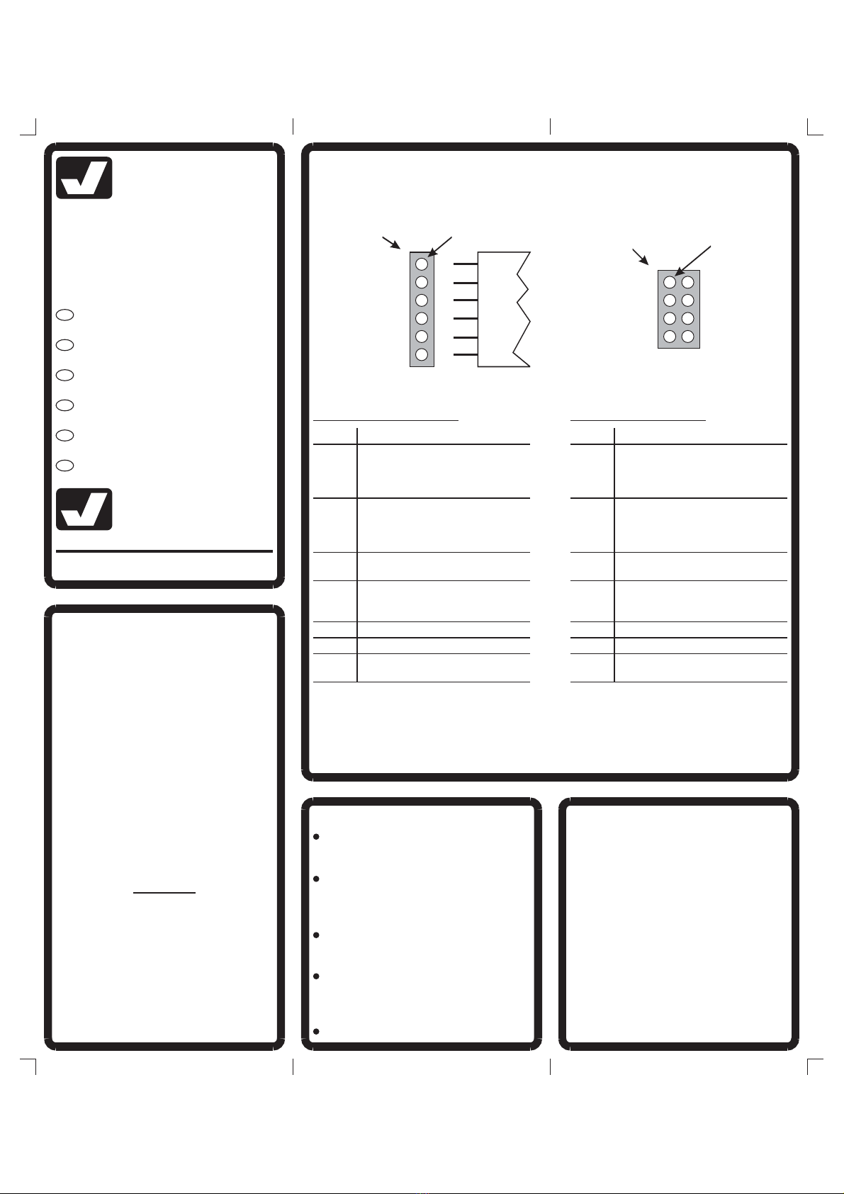
Highly flexible cables 0.04 mm² sorted in
various colours. For wiring between
locomotive decoders and locomotive or
car.
Heat-shrinkable tube sections 1.2 mm
Ø, shrinkage rate 1:2, sorted in various
colours. For insulating solder
connections for flexible wires.
Sections of extra thin hard PVC heat-
shrinkable tube, shrinkage rate 1:2. For
insolating locomotive decoders.
Especially thin special solder for
soldering cables to locomotive decoders
and connecting the highly flexible cables
to each other.
Two-sided adhesive pads for attaching
the decoder inside the vehicle.
Cut the heat-shrinkable tube to the desired
length and push it over the part to be
covered. Shrink the tube with a hot air gun
(not a hair drier!). You can also hold a hot
soldering iron under the tube, however
4. Lötanleitung
Wenn Sie im Löten noch nicht so geübt
sind, lesen Sie bitte zuerst diese Lötanlei-
tung, bevor Sie zum Lötkolben greifen.
Denn Löten will gelernt sein.
1. Verwenden Sie beim Löten von elektro-
nischen Schaltungen grundsätzlich nie
Lötwasser oder Lötfett. Diese enthalten
eine Säure, die Bauteile und Leiterbah-
nen zerstört.
2. Als Lötmaterial darf nur Elektronikzinn
mit einer Kolophoniumseele verwendet
werden, die zugleich als Flussmittel
dient (entsprechend dem beiliegenden
Lötzinn).
3. Verwenden Sie einen kleinen Lötkolben
mit maximal 30 Watt Heizleistung und
einer dünnen Lötspitze (< 1 mm). Die
Lötspitze muss zunderfrei sein, damit
die Wärme gut abgeleitet werden kann.
D.h., die Wärme vom Lötkolben muss
gut an die zu lötende Stelle geleitet
werden.
4. Die Lötung selbst soll zügig vorgenom-
men werden, denn durch zu langes Lö-
ten werden Bauteile zerstört. Ebenso
kann es zum Ablösen der Lötaugen und
Leiterbahnen von Platinen führen.
5. Kabel werden zunächst am Ende abiso-
liert, verdrillt und dann verzinnt. Zum
Löten wird dann die gut verzinnte Löt-
spitze so auf die Lötstelle gehalten,
dass zugleich beide zu verbindende
Komponenten berührt werden. Gleich-
zeitig wird (nicht zuviel) Lötzinn zuge-
führt und mit aufgeheizt. Sobald das
Lötzinn zu fließen beginnt, nehmen Sie
es von der Lötstelle fort. Jetzt warten
Sie noch einen Augenblick, bis das zu-
rückgebliebene Lot gut verlaufen ist
und nehmen dann den Lötkolben von
der Lötstelle ab.
6. Achten Sie darauf, dass das soeben
angelötete Kabel, nachdem Sie den
Lötkolben abgenommen haben, ca. 5
Sekunden lang nicht bewegt wird. Zu-
rück bleibt dann eine silbrig glänzende,
einwandfreie Lötstelle.
7. Voraussetzung für eine einwandfreie
Lötstelle und gutes Löten ist eine sau-
bere, nicht oxidierte Lötspitze. Denn mit
einer schmutzigen Lötspitze ist es ab-
solut unmöglich, sauber zu löten. Neh-
men Sie daher nach jedem Löten über-
flüssiges Lötzinn und Schmutz mit
einem feuchten Schwamm oder einem
Silikonabstreifer vom Kolben ab.
8. Nach dem Löten werden überstehende
blanke Enden der Kabel direkt über der
Lötstelle mit einem Seitenschneider ab-
geschnitten, vorzugsweise mit einem
Seitenschneider Wate (Schräge).
9. Beim Löten an elektronischen Bauteilen
ist besonders darauf zu achten, dass
eine Lötzeit von ca. 5 Sekunden nicht
überschritten wird, da sonst die Bautei-
le zerstört werden.
ohne
4. Soldering Instructions
If you are not practiced at soldering, please
first read these soldering instructions be-
fore picking up the soldering iron. Solde-
ring is something that has to be learned.
1. Never use soldering paste or fluid when
soldering electronic connections. These
contain an acid that destroys cables,
components and conductor paths.
2. As the soldering material, use only
electronics solder with a rosin core,
which also acts as a fluxing agent (like
the enclosed solder).
3. Use a small soldering iron with max. 30
watt power and a thin soldering tip (< 1
mm). The soldering tip must be free of
scaling so that the heat can be conduc-
ted away well. This means that the heat
from the soldering iron must be conduc-
ted well to the point to be soldered.
4. The soldering itself should be done
quickly because soldering for too long
can destroy components. It also leads
to loosening of the soldering pads and
conductor paths from PCBs.
5. At first strip the insulation from the ends
of the cable
Then presol-
der the wires. To solder, the well-tinned
soldering tip is placed at the soldering
point so that both components which
you want to connect are contacted. At
the same time (not too much) solder
has to be added and heated. As soon
as the solder begins to flow, remove it
from the soldering point. Then wait a
moment until the remaining solder has
run well, and then remove the soldering
iron from the soldering point.
6. Ensure that the cable just soldered is
not moved for approx. 5 seconds after
you have removed the soldering iron.
Then only a shiny silver, perfect solde-
ring point remains.
7. A clean, unoxidized soldering tip is re-
quired for a perfect soldering point. It is
absolutely impossible to solder cleanly
using a dirty soldering tip. You should
therefore always remove excess solder
and dirt from the iron with a moist
sponge or a silicon wiper after making a
soldering point.
8. Uninsolated ends of the wire which
looks out are cut off directly above the
soldering point with a wire cutter. We
recommend a f wire cutter.
9. When welding electronic components,
be sure not to solder for more than 5
seconds, because otherwise the
components will be destroyed.
, and twist the stripped ends
between your finger tips.
ull-flush
without touching the tube. The tubes shrink
very quickly. Avoid overheating! Bubble
formation, discoloration, or ripping of the
hose (especially for hard PVC heat-
shrinkable tube) are caused by this.