manuals.online logo
Brands
  1. Home
  2. •
  3. Brands
  4. •
  5. Volvo
  6. •
  7. Automobile Accessories
  8. •
  9. Volvo 2003 XC90 User manual

Volvo 2003 XC90 User manual

Other manuals for 2003 XC90

2

This manual suits for next models

7

Other Volvo Automobile Accessories manuals

Volvo 30664082 User manual

Volvo

Volvo 30664082 User manual

Volvo Load carriers User manual

Volvo

Volvo Load carriers User manual

Volvo 31330255 User manual

Volvo

Volvo 31330255 User manual

Volvo VBB4 User manual

Volvo

Volvo VBB4 User manual

Volvo 281350 User manual

Volvo

Volvo 281350 User manual

Volvo 31334457 User manual

Volvo

Volvo 31334457 User manual

Volvo Handsfree User manual

Volvo

Volvo Handsfree User manual

Volvo 31285564 User manual

Volvo

Volvo 31285564 User manual

Volvo TRM User manual

Volvo

Volvo TRM User manual

Volvo 283469-5 User manual

Volvo

Volvo 283469-5 User manual

Volvo 30795637 User manual

Volvo

Volvo 30795637 User manual

Volvo Centrax Configuration guide

Volvo

Volvo Centrax Configuration guide

Volvo Mode 2 User manual

Volvo

Volvo Mode 2 User manual

Volvo 2000 User manual

Volvo

Volvo 2000 User manual

Volvo 2003 XC90 User manual

Volvo

Volvo 2003 XC90 User manual

Volvo HITCH BIKE RACK User manual

Volvo

Volvo HITCH BIKE RACK User manual

Volvo 30754484 User manual

Volvo

Volvo 30754484 User manual

Volvo 912-D User manual

Volvo

Volvo 912-D User manual

Volvo 30739998 User manual

Volvo

Volvo 30739998 User manual

Volvo MY18 User manual

Volvo

Volvo MY18 User manual

Volvo 31316493 User manual

Volvo

Volvo 31316493 User manual

Volvo 31269367 User manual

Volvo

Volvo 31269367 User manual

Volvo SENSUS User manual

Volvo

Volvo SENSUS User manual

Volvo 30758234 User manual

Volvo

Volvo 30758234 User manual

Popular Automobile Accessories manuals by other brands

Magneti Marelli AC161 Installation instruction

Magneti Marelli

Magneti Marelli AC161 Installation instruction

FDI uEZ GUI Start here

FDI

FDI uEZ GUI Start here

JCROffroad JT Install instructions

JCROffroad

JCROffroad JT Install instructions

Rostra VOXXElectronics 250-1930 owner's guide

Rostra

Rostra VOXXElectronics 250-1930 owner's guide

TOP VEHICLE TECH GR3FORD5 installation manual

TOP VEHICLE TECH

TOP VEHICLE TECH GR3FORD5 installation manual

Safe Fleet PRIME DESIGN AR-2000-BLK manual

Safe Fleet

Safe Fleet PRIME DESIGN AR-2000-BLK manual

Skoda Fabia Combi 5J Fitting instructions

Skoda

Skoda Fabia Combi 5J Fitting instructions

Camcar 40077 Al Mounting instructions

Camcar

Camcar 40077 Al Mounting instructions

Camcar 40089 AL Mounting instructions

Camcar

Camcar 40089 AL Mounting instructions

Impac Tradesman 2000 installation manual

Impac

Impac Tradesman 2000 installation manual

DVB OFFROAD BRSB-01 installation manual

DVB

DVB OFFROAD BRSB-01 installation manual

Safari Snorkel SS385HF installation guide

Safari Snorkel

Safari Snorkel SS385HF installation guide

ULTIMATE SPEED 279746 Assembly and Safety Advice

ULTIMATE SPEED

ULTIMATE SPEED 279746 Assembly and Safety Advice

SSV Works DF-F65 manual

SSV Works

SSV Works DF-F65 manual

ULTIMATE SPEED CARBON Assembly and Safety Advice

ULTIMATE SPEED

ULTIMATE SPEED CARBON Assembly and Safety Advice

Witter F174 Fitting instructions

Witter

Witter F174 Fitting instructions

WeatherTech No-Drill installation instructions

WeatherTech

WeatherTech No-Drill installation instructions

TAUBENREUTHER 1-336050 Installation instruction

TAUBENREUTHER

TAUBENREUTHER 1-336050 Installation instruction

manuals.online logo
manuals.online logoBrands
  • About & Mission
  • Contact us
  • Privacy Policy
  • Terms and Conditions

Copyright 2025 Manuals.Online. All Rights Reserved.

XC90
Section
Group
Weight(Kg/Pounds)
Year
Month
3
39
2004
04
XC90 2003, XC90 2004, XC90 2005, XC90 2006, XC90 2007, XC90 2008, XC90 2009, XC90 2010
Replaces issue: 2002 05
XC90
Section
Group
Weight(Kg/Pounds)
Year
Month
3
39
2004
04
XC90 2003, XC90 2004, XC90 2005, XC90 2006, XC90 2007, XC90 2008, XC90 2009, XC90 2010
Replaces issue: 2002 05
Installation instructions, accessories
-
Subwoofer
Volvo Car Corporation G
öteborg, Sweden
Installation instructions, accessories
-
Subwoofer
Volvo Car Corporation G
öteborg, Sweden
©
VolvoCar Corporation, 2004 Printed in Sweden
9162298
©
VolvoCar Corporation, 2004 Printed in Sweden
9162298
Page 1 of 20
Required tools
A0000162
A0801178
A0000161
R8802817
R3903989
Installation instructions, accessories
-
Subwoofer
Volvo Car Corporation G
öteborg, Sweden
Installation instructions, accessories
-
Subwoofer
Volvo Car Corporation G
öteborg, Sweden
©
VolvoCar Corporation, 2004 Printed in Sweden
9162298
©
VolvoCar Corporation, 2004 Printed in Sweden
9162298
Page 2 of 20
Any comments on this publication? Please contact your nearest dealer. Thank you!
R3904979
Publication no: MA 9162298, Issue: 2004
-04
Comments:..........................................................................................................
............................................................................................................................
............................................................................................................................
............................................................................................................................
............................................................................................................................
.............................................................................................................................
From:...................................................................................................................
Address:.............................................................................................................
Telephone no:................................................................................................... .
Telefax:...............................................................................................................
Installation instructions, accessories
-
Subwoofer
Volvo Car Corporation G
öteborg, Sweden
Installation instructions, accessories
-
Subwoofer
Volvo Car Corporation G
öteborg, Sweden
©
VolvoCar Corporation, 2004 Printed in Sweden
9162298
©
VolvoCar Corporation, 2004 Printed in Sweden
9162298
Page 3 of 20
INTRODUCTION
●NOTE! Read through the whole installation instruction
before starting the work.
●The front page gives the date of this edition and the edition it
replaces
●The second page shows the tools needed for the installation and
the contents of the installation kit
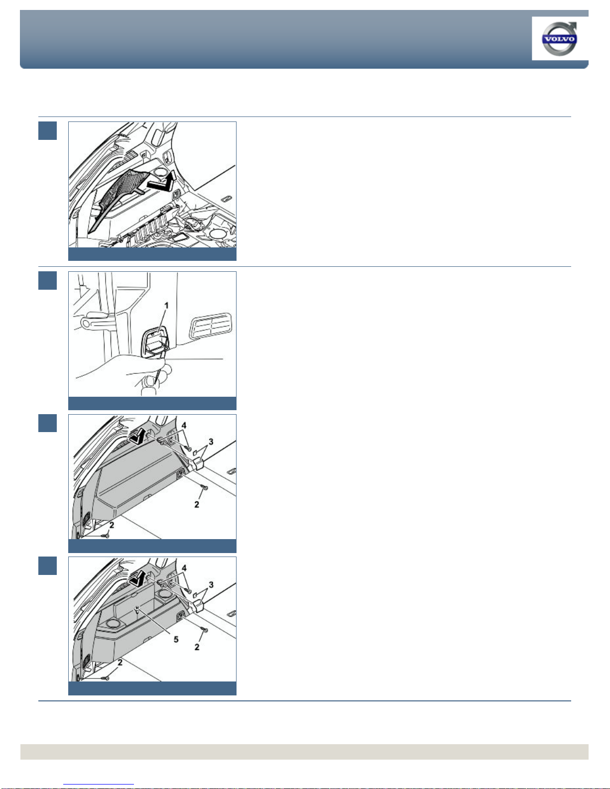
●The illustrations display the procedure in order of operation. The
order of operation is repeated in the text section
●Cut out the text page in order to follow the illustrations and text at
the same time.
Cars equipped with SRS/SIPS (Airbag)
Warning!
Extra care must be taken when working on cars equipped with SRS/SIPS
air bags. This is important to prevent:
1. Personal injury
2. Damage to or malfunction of the SRS/SIPS system.
Work on the SRS/SIPS systems or related components must always be
carried out by an authorised Volvo workshop.
Is the car equipped with SRS (supplemental restraint system)?
Cars equipped with a driver's airbag have the letters "SRS" imprinted on
the centre panel of the steering wheel. Cars equipped with driver's and
passenger airbags are marked with "SRS" on both the steering wheel
centre panel and also on the dashboard close to the airbag.
If the car is equipped with SIPS (side impact protection system ) a "SIPS"
decal is marked on both the front seats.
Cars equipped with inflatable curtains have the marking "SRS" on one of
the panels along the posts on the inside of the car.
Cars equipped with SRS (supplemental restraint system) also have an
"SRS" decal on the front windscreen.
Do not damage the SRS wiring!
Do not trap, chafe, pierce or damage the SRS wiring. SRS wiring has
orange casing and/or is plaited.
Steering and front suspension
The contact reel in the SRS system can easily be damaged when
working on the steering wheel, steering shaft or steering gear. Refer to
the SRS (supplemental restraint system) Service Manual or service
instructions in VIDA for information on carrying out such work. This is to
prevent damage.
SRS warning lamp
If the SRS warning lamp lights after repairs have been carried out, take
the car to an authorised Volvo workshop.
SRS
collision sensor control module
S60 / V70 (00-) / S80 / XC90
The collision sensor control module is located on the tunnel under the
centre console, in front of the parking brake.
Installation instructions, accessories
-
Subwoofer
Volvo Car Corporation G
öteborg, Sweden
Installation instructions, accessories
-
Subwoofer
Volvo Car Corporation G
öteborg, Sweden
©
VolvoCar Corporation, 2004 Printed in Sweden
9162298
©
VolvoCar Corporation, 2004 Printed in Sweden
9162298
Page 4 of 20
CAUTION!
The air bag inflation areas must not be obstructed. Never place
any objects, such as upholstery or accessories, within these
areas. The panels must be able to open in the correct manner at
the right time, otherwise there is an increased risk of personal
injury in the event of a collision.
CAUTION!
The ignition must be in position "0" and the key removed from
the ignition switch if any connector in the SRS system is to be
unplugged. Then wait at least one minute and disconnect the
battery negative lead before unplugging any of the connectors.
When work is completed, the ignition key must be turned to
position "II" before reconnecting the battery negative lead.
Subwoofer
Note!
This accessory requires software unique to the car
Note!
Points 4
-10, 12, 21 -31 and 38 only apply to cars up to and including
model year
-
2004 (CH
-133999)
Points 32
-37 and 39 only apply to cars from model year 2005-(
CH
134000-).
Installation instructions, accessories
-
Subwoofer
Volvo Car Corporation G
öteborg, Sweden
Installation instructions, accessories
-
Subwoofer
Volvo Car Corporation G
öteborg, Sweden
©
VolvoCar Corporation, 2004 Printed in Sweden
9162298
©
VolvoCar Corporation, 2004 Printed in Sweden
9162298
Page 5 of 20
1
A8800136
Preparatory work
●Move the left front seat as far forward as possible
●
Turn the ignition key to position 0
●Disconnect the battery negative lead.
Note!
Wait at least five minutes before disassembling the connectors or removing
other electrical equipment
2A
R8902691
2B
R8903031
Preparatory work
Illustration A
Applies to cars with two rows of seats
●Fold up the centre rear floor hatch slightly
●Remove the hatch by pulling it off the mountings at the front edge
●Remove the storage box underneath and lift it out. If the floor hatch has a carrier
bag holder on the underneath, it is secured by a strap on each of the shorter
sides of the storage box. These straps must be undone
●Remove the front floor hatch in the same way. (Applies to cars up to and
including model year
-
2004 (CH
-133999)).
Illustration B
Applies to cars with three rows of seats and the integrated carrier bag
holder on the underside of the centre floor hatch
●Fold up the centre rear floor hatch (1)
●Release the two straps on the panel underneath. Lift up the panel at the rear
edge. Fold back the floor hatch towards the panel. Lift out the floor hatch and
panel.
Applies to the XC90 with three rows of seats without integrated
carrier bag holders
●Fold up the centre rear floor hatch (1) at the rear edge and lift it out.
Installation instructions, accessories
-
Subwoofer
Volvo Car Corporation G
öteborg, Sweden
Installation instructions, accessories
-
Subwoofer
Volvo Car Corporation G
öteborg, Sweden
©
VolvoCar Corporation, 2004 Printed in Sweden
9162298
©
VolvoCar Corporation, 2004 Printed in Sweden
9162298
Page 6 of 20
3
R8903030
Preparatory work
●Remove the side floor hatch (A) and the folding side panel (B) on the left-hand
side in the cargo compartment.
4
R8504293
Preparatory work
Applies to cars up to and including model year -
2004 (CH
-133999)
Applies to cars with two rows of seats
●Remove the front storage compartment.
5
R8504308
Preparatory work
●Remove the rear panel on the left rear mounting on the left-hand front seat. Pry
up the rear edge of the panel slightly and then pull backwards and upwards.
6
R8504210
Preparatory work
●Carefully pry off the panel above the joint between the left-hand door sills, at the
lower edge. Use a weatherstrip tool.
Installation instructions, accessories
-
Subwoofer
Volvo Car Corporation G
öteborg, Sweden
Installation instructions, accessories
-
Subwoofer
Volvo Car Corporation G
öteborg, Sweden
©
VolvoCar Corporation, 2004 Printed in Sweden
9162298
©
VolvoCar Corporation, 2004 Printed in Sweden
9162298
Page 7 of 20
7
R8504309
Preparatory work
●Remove the panel for the front mounting on the left-hand seat in the second row
of seats by pressing down the catch (1) on top and detaching the panel by
pulling it forward
●Remove the screw underneath.
8
R8504310
Preparatory work
●Remove the panel for the front mountings on the centre and left-hand seat in the
second row. Press down the catches (1) on top and detach the panel by pulling
it forward
●
Remove the left
-hand screw underneath.
9
R8504311
Preparatory work
Applies to cars with two rows of seats
●Fold the backrest on the left-hand seat in the second row of seats forwards.
Applies to cars with three rows of seats
●
Fold the left
-hand seat backrest forwards in the second row. Slide the backrest
forward as far as possible.
Applies to all models
●Remove the covers for the rear mountings for the left-hand seat in the second
row. Pry the covers off at the rear edge
●Remove the screws underneath.
10A
R8504312
Preparatory work
Illustration A
●Detach the top edge of the sill trim panel to access the seat belt mounting in the
end mounting.
Illustration B
●Remove the seat belt from the end mounting. First carefully press down the lug
as illustrated in illustration B so that the seat belt releases from the end mounting.
Installation instructions, accessories
-
Subwoofer
Volvo Car Corporation G
öteborg, Sweden
Installation instructions, accessories
-
Subwoofer
Volvo Car Corporation G
öteborg, Sweden
©
VolvoCar Corporation, 2004 Printed in Sweden
9162298
©
VolvoCar Corporation, 2004 Printed in Sweden
9162298
Page 8 of 20
10B
R8803236
Use a weatherstrip tool.
Illustration A
●
Continue to pull off the sill trim panel until the remaining clips release
●
Unhook the sill trim panel from the B
-
post panel. Place the sill trim panel in the
cargo compartment
●
Remove the seat.
Note!
Lift the seat out of the passenger compartment carefully. Ensure that the
mountings do not damage the door panels.
11
R3903738
Preparatory work
Applies to all models
●Pull off the rubber strip at the rear edge of the door opening for the left-hand rear
door opposite the left C-post panel
●Carefully pry off the left-
hand C
-post panel at the sides at the top edge. Use a
plastic weatherstrip tool. Pull off until the three clips on the inside release. Do not
damage the headlining or the panel
●Remove the panel by pulling upwards slightly and unhooking it from the side
panel.
12
R8504307
Preparatory work
Applies to cars up to and including model year -
2004 (CH
-133999)
●Fold up the floor carpet. Secure the floor carpet using one of the seat belts
●Carefully fold up the insulation. Place a shim underneath so that the connector
bridge can be exposed.
Note!
Do not damage the insulation. It is brittle and breaks easily.
13
R8504084
Preparatory work
Applies to all models
●Remove the covers and the screws underneath for the rear headlining
●Carefully pry off the panel at the rear edge. Use a plastic weatherstrip tool
●Pull the rear edge of the panel downwards until all clips on the inside have
released
●Disconnect the connector for the rear roof lighting (applies to cars with three
rows of seats)
Installation instructions, accessories
-
Subwoofer
Volvo Car Corporation G
öteborg, Sweden
Installation instructions, accessories
-
Subwoofer
Volvo Car Corporation G
öteborg, Sweden
©
VolvoCar Corporation, 2004 Printed in Sweden
9162298
©
VolvoCar Corporation, 2004 Printed in Sweden
9162298
Page 9 of 20
●Pull the panel backwards to release it.
14
R8504123
Preparatory work
●Pull off the left-
hand D
-post panel starting at the top edge. Then pull downwards
until the three clips on the inside have released. Do not damage the panel
●Remove the panel by pulling upwards slightly and unhooking it from the side
panel. Disconnect the connector if the car has a loudspeaker in the D-post.
15A
R8504313
15B
R8504315
15C
R8504316
Preparatory work
Illustration A shows the removal of the cover for the load securing eyelets for
all models
●Fold out the load securing eyelet
●Insert a scriber with an angled tip into the hole in the top of the cover
●Turn the scriber so that the angled tip engages in the reverse of the cover (1).
Pull the cover off.
Illustration B applies to cars with two rows of seats
Illustration C applies to cars with three rows of seats
●Fold up the seats in the third row (applies to cars with three rows of seats)
●Remove the screws (2) for the load securing eyelets in the left-
hand side panel
●Remove the covers (3) over the front mountings for the left-
hand side panel. Pry
the covers off. Use a plastic weatherstrip tool or a small screwdriver
●Remove the screws (4)
●
Remove the clip (5) at the bottom of the storage compartment in the panel
(Applies to cars with three rows of seats)
●
Pull up the panel slightly at the top edge so that the clips on the inside release.
Remove the panel by pulling it straight upwards.
Installation instructions, accessories
-
Subwoofer
Volvo Car Corporation G
öteborg, Sweden
Installation instructions, accessories
-
Subwoofer
Volvo Car Corporation G
öteborg, Sweden
©
VolvoCar Corporation, 2004 Printed in Sweden
9162298
©
VolvoCar Corporation, 2004 Printed in Sweden
9162298
Page 10 of 20