VWR avantor CO-2500L User manual

D
Instruction manual
VWR® CONDUCTIVITY METER CO-2500L
EU cat no 663-0372
Version 1 1 Issue: 12 2021

Legal address of Manufacturer
Europe
VWR International bv,
Researchpark Haasrode 2020
Geldenaaksebaan 464 B- 001 Leuven
+ 216 85011
be.vwr.com
UK Importer:
VWR International Ltd
Hunter Boulevard, Magna Park
Lutterworth, Leicestershire, LE17 4XN
uk.vwr.com
Country of Origin
POLAND

CONTENT
I. Introduction......................................................................................................................1
1. Package content.........................................................................................................2
2. Disclaimer...................................................................................................................2
. Characteristics of the meter........................................................................................
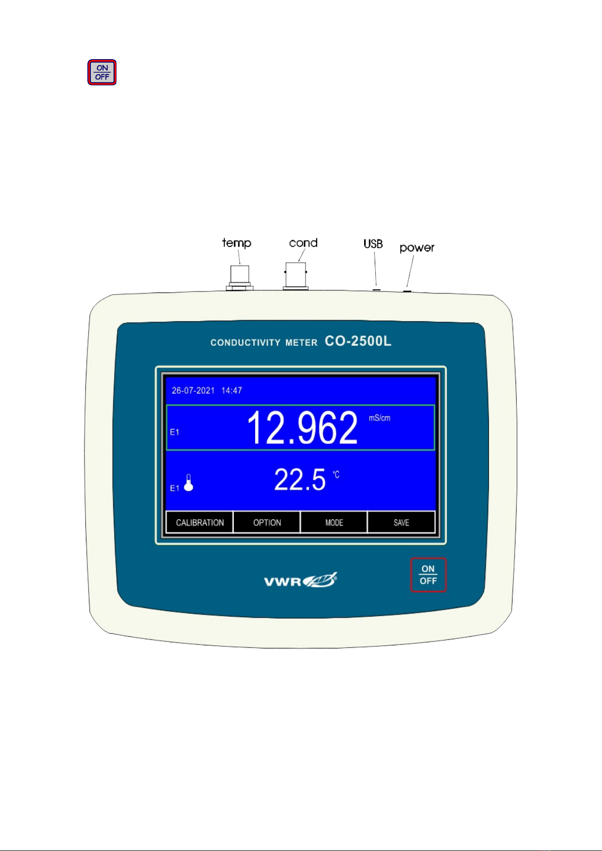
4. The outside view.........................................................................................................4
5. The meter‘s maintenance...........................................................................................6
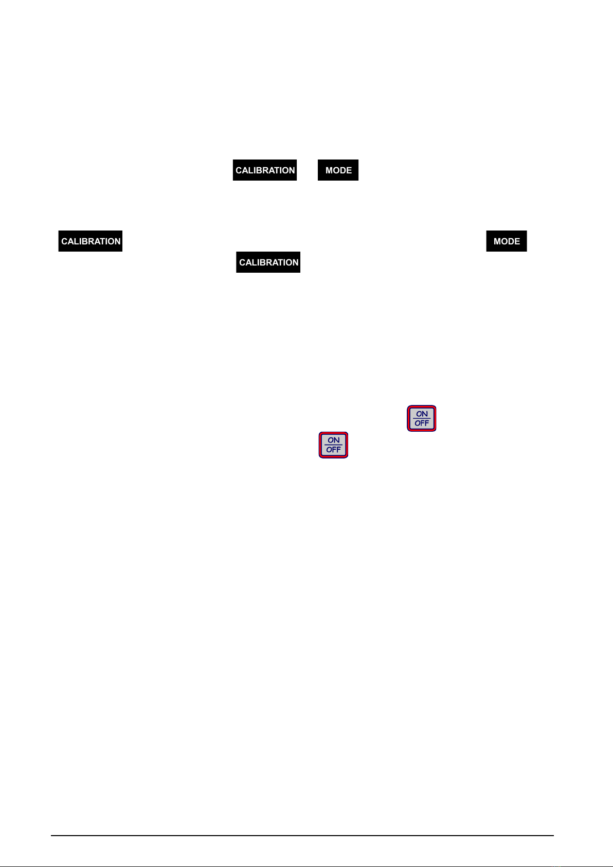
6. Switching the meter on and off...................................................................................7
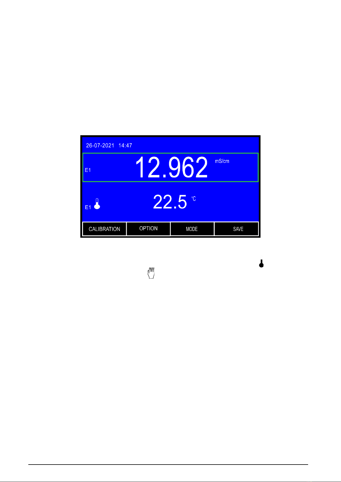
6.1. Stabilised reading.............................................................................................8
7. Preparation to work....................................................................................................9
7.1. Choosing the kind of the temperature compensation......................................9
II. Conductivity and salinity measurement.....................................................................10
8. Entering the conductivity parameters.......................................................................11
8.1. Resolution.......................................................................................................12
8.2. Cell number....................................................................................................12
8. . Choosing the unit............................................................................................12
8.4. Calibration points and date.............................................................................14
8.5. Calibration validity time...................................................................................14
8.6. Choosing the type of temperature compensation..........................................14
8.7. Entering the a coefficient................................................................................15
8.8. Entering the reference temperature...............................................................15
8.9. Entering the WTDS coefficient...........................................................................15
9. Maintenance of the conductivity cell.........................................................................16
10. Calibration...............................................................................................................17
10.1. Calibration without standard solution...........................................................18
10.2. Calibration with use of standard solution.....................................................19
10.2.1. Entering the standard solution value..........................................................20
10.2.2. Calibration with automatic temperature compensation..............................21
10.2. . Calibration with manual temperature compensation..................................2
11. Conductivity measurement.....................................................................................25
11.1. Measurement without temperature compensation.......................................25
11.2. Measurement with automatic temperature compensation...........................26
11. . Measurement with manual temperature compensation...............................27
12. Salinity and total dissolved solids measurement....................................................28
12.1. Salinity measurement with conversion to NaCl or KCl.................................29
1 . Notices about temperature compensation............................................................. 0
1 .1. Natural water................................................................................................ 0
1 .2. Ultra pure water............................................................................................ 0
III. Temperature measurement.........................................................................................32
14. Setting the temperature measurement parameters...............................................
14.1. Resolution.....................................................................................................
14.2. Probe number............................................................................................... 4
14. . Sensor group................................................................................................ 4
14.4. Unit............................................................................................................... 4
14.5. Temperature of the manual compensation.................................................. 4
15. Temperature measurement.................................................................................... 5
I . Options.........................................................................................................................36
16. Option screen......................................................................................................... 7
16.1. Function........................................................................................................ 7
16.2. Series............................................................................................................ 8
16. . Miscellaneous............................................................................................... 8
16.4. Info................................................................................................................40

17. Recording the readings, memory readout..............................................................41
17.1. Storage parameters......................................................................................41
17.2. Entering single readings into the memory....................................................42
17. . Collecting measurement series....................................................................4
17.4. Mode of holding readings (HOLD)................................................................44
17.5. Viewing the readings....................................................................................45
18. Calibration report....................................................................................................46
19. Communication with a PC......................................................................................46
20. Technical data........................................................................................................48
21. Ordering information...............................................................................................50
22. Technical service....................................................................................................51
2 . Warranty.................................................................................................................51
24. Equipment disposal................................................................................................52

- 1 -
I. INTRODUCTION

- 2 -
1. PACKAGE CONTENT
1. CO-2500L conductivity meter.
2. Stainless steel temperature sensor
. Plastic body, metal electrodes conductivity cell.
4. 12,90 mS/cm conductivity controlling solution – 50 ml.
5. 5V/1000mA power adapter.
6. Free standing electrode holder.
7. USB cable for connecting with a PC
8. Cartoon box for the meter with accessories.
2. DISCLAIMER
Dear User!
Wide range of functions requires careful reading of the manual, in other
case some of the features may stay unused or using the meter may be
troublesome.
Using electrodes and cells of good quality and replacing them after a suitable
time provides obtaining high measuring accuracy. It is worth remembering that
electrodes have much shorter life time than the meter.
Clean membrane is the main condition of correct readings. After each
measurement the membrane should be rinsed with distilled water. Oil, pastes,
grease, etc., should be removed according to the instructions provided in the
electrode’s manual.
We wish a pleasant and trouble-free work with our meter.
User‘s manual for CO-2500L conductivity meter v1.0x

- -
3. CHARACTERISTICS OF THE METER
CO-2500L waterproof conductivity meter belongs to the newest generation of
measuring devices. The meter provides high accuracy and repeatability of
readings. The meter’s memory is independent from power supply. The meter
is equipped with a large backlit custom LCD, which can simultaneously display
conductivity and temperature readings. Thanks to its touchscreen keyboard
the operation of the meter is very comfortable.
The most important features of CO-2500L are:
- automatic or manual temperature compensation;
-- storing of the calibration date and parameters of three cells;
- wide range of conductivity measurement with six automatically switched
subranges (autorange);
- converting conductivity to salinity in NaCl or KCl (g/l or %) according to
actual dependence to conductivity;
-converting conductivity into TDS (g/l or %) with possibility of introducing the
TDS coefficient;
-measurement of resistivity in *cm;
-automatic introduction of temperature compensation coefficient a for
measurements in natural, pure and ultra pure water;
- calibration of the conductivity cell by introducing the K constant or with use
of 1 - standard solutions;
- possibility of determining K constant of the conductivity cell;
- possibility of introducing the date of calibration validity termination and
signalling its expiry;
-signalising of the reading stabilisation (READY);
-holding the reading on the display (HOLD);
-storing measurement results with time, date and temperature, taken as
single or series of measurements with set time interval;
-possibility to create the last calibration report or reading of last 10 calibration
data of each measuring function in the data transmission software;
-USB output for connecting with PC;
- graphic display with brightness control and touchscreen;
- real time clock with date;
- energy saving mode activated after time set by the user.

- 4 -
4. THE OUTSIDE IEW
On the front wall of the meter there is a graphic LCD placed (Pic. 1), on which
the following readings are displayed:
-conductivity or salinity, TDS, resistivity;
-temperature.
At the top of the LCD the current time and date are displayed.
Choosing particular functions is described in the chapter 16.1. Symbols of the
units are displayed next to the readings.
Pic. 1.
The automatic temperature compensation is signalised by the symbol, the
manual compensation – by the symbol (next to the temperature reading).
Number of the chosen cell is displayed on the left (E1, E2 or E3). It informs,
which of the recorded characteristics will be taken into consideration during
all calculations. Red colour of the electrode number informs about erased
characteristic, yellow – calibration validity date expiry. The parameter screen
of each function displays all parameters entered by the user.
User‘s manual for CO-2500L conductivity meter v1.0x

- 5 -
The button (Pic. 2) placed below the display is used for switching the
meter on and off.
In the back wall of the meter the sockets are placed with the symbols given
below:
temp -RCA (Chinch) socket to connect the temperature probe;
cond -BNC-50 socket for connecting the conductivity cell.
USB -USB socket for connecting with a PC;
power -DC2.5 socket for connecting the power adapter;
Pic. 2.
.

- 6 -
5. THE METER‘S MAINTENANCE
The meter is equipped with a graphic touchscreen. The maintenance consists
in pressing particular keys and windows which appear on the screen. Grey
captions in the windows and keys inform that these elements are not active in
this particular operating mode. Particular keys, connected with the
measurement function (i.e. or ) become active after selecting
the chosen function. To select, press the screen in a freely chosen spot of the
chosen function. Around this spot a frame will be displayed. To deselect,
press the spot again. If the chosen function has a possibility of calibration, the
key becomes active. If it has additional parameters, the key
also becomes active. The key is the only key in the meter that
responds exclusively to a long press (about 2 sec.). It prevents from
accidental erase of the electrode (cell) calibration data.
Entering wrong value, attempt of calibration when the meter doesn‘t
recognise the standard or attempt to turn the meter off when series collecting
proceeds are signalised by a triple warning sound, irrespective of the chosen
sound settings.
Turn the meter on and off with one mechanical button. When a
measurement series is collected, the button is not active until the
process of collecting ends or is stopped.
User‘s manual for CO-2500L conductivity meter v1.0x

- 7 -
6. SWITCHING THE METER ON AND OFF
After switching the meter on with the button, the memory test proceeds.
If the test ends successfully, the meter enters the measurement screen with
settings entered before switching it off previously. In case of detecting the
manufacturer‘s calibration data loss, the following information will appear:
Pressing the button accepts standard manufacturer‘s calibration
parameters and enters the measurement screen. Such situation will be
repeating each time the meter is switched on and requires sending the meter
to the manufacturer for servicing.
In case of the user‘s data loss (i.e. the constant K of the conductivity cell), the
following information will appear:
Pressing the button accepts and records in the memory standard pH
electrode characteristic and enters the measurement screen. In such case,
calibration of the pH electrode is necessary. Analogical situation occurs in
case of other measuring functions. Repeating of the situation after switching
the meter on again informs about the EEPROM memory malfunction and
requires sending the meter to the manufacturer for servicing.
Switch the meter off by pressing the button. During the process of
collecting series it is impossible to turn the meter off.

- 8 -
6.1. Stabilised reading
The stabilised reading signalisation is active only for the reading marked with
a frame. If the measured value meets the criterium of the stabilised reading, it
is signalised by green colour of the frame and additionally with a sound if it
has been activated. In this mode the meter does not record changes of the
measured value in a certain range and does not display them. The meter
exits the stabilised reading mode after exceeding this range, the frame
changes colour to white and the meter displays the current measurement
value. In practice, lowering accuracy in this mode is insignificant.
To turn on the stabilised reading signalisation on the measuring screen press
the button, the option screen will display with the FUNCTION tab open
containing the previously set configuration (Pic. A).
Pic.
After pressing the window with the actually chosen option a table with
following buttons will be displayed (Pic. B):
- the stabilised reading signalisation is off;
- the stabilised reading signalised with changing the frame
colour from white to green (only for reading marked with a
frame);
- the stabilised reading signalised by colour change and sound.
Return to the measurement screen by pressing the button.
User‘s manual for CO-2500L conductivity meter v1.0x

- 9 -
7. PREPARATION TO WORK
Before starting work:
- connect the power adapter to the power socket;
-connect conductivity cell to the cond (BNC-50) socket;
-in case of using the temperature probe connect it to the temp (RCA)
temperature socket;
-in case of working with a PC connect a suitable cable to the USB socket;
-switch the meter on by pressing the button.
7.1. Choosing the kind of the temperature compensation
The meter switches to the automatic or manual temperature compensation
mode itself. Connecting the temperature probe switches the automatic
temperature compensation on. Next to the reading the symbol is displayed.
After disconnecting the probe the meter enters the manual temperature
compensation mode. Instead of the symbol the is displayed. In case of
the manual temperature compensation the temperature value is set on the
temperature measurement parameters screen (point 14.5).

- 10 -
II. CONDUCTI ITY AND SALINITY
MEASUREMENT
User‘s manual for CO-2500L conductivity meter v1.0x

- 11 -
8. ENTERING THE CONDUCTI ITY PARAMETERS
Before starting calibration and measurements it is necessary to perform all
activities described in the chapter 7. Additionally, according to the chapter
below, it is necessary to choose the unit in which the calibration and
measurement are going to be made.
The parameters screen is entered by pressing the conductivity reading (a
frame will display around it Pic. 4A), and next pressing the button. This
screen (Pic. 4B) enables choosing resolution, the cell number, unit, checking
the calibration point and date, entering the calibration validity time, a
coefficient, reference temperature and TDS coefficient.
Pic. 4

- 12 -
When the parameters are entered, return to the measurement screen by
pressing the button.
8.1. Resolution
The reading may be displayed with low or high resolution.
After pressing the RESOLUTION window, choose:
- ½ digit measurement resolution;
- 4½ digit measurement resolution.
8.2. Cell number
If the meter stores more than one cell characteristic, the cell may be replaced
without calibration. This option is very useful in case of using different types of
cells, i.e. for sewage, clear water etc. After pressing the PROBE NO window the
table appears (Pic. 4C), from which its possible to choose one of the
characteristics stored under E1, E2 or E3 number. The number‘s colour
informs about the cell‘s condition:
white - cell calibrated;
yellow - the calibration validity date expired;
red - calibration data erased (default value K = 1.000 cm-1),
the cell calibration necessary.
8.3. Choosing the unit
The reading may be displayed in units of conductivity, resistivity or salinity.
Salinity can be counted to NaCl, KCl or TDS content. The result can be
displayed in % of weight concentration or in g/l. To choose the unit, press
the UNIT window. The screen for choosing the unit will appear (Pic. 5A).
User‘s manual for CO-2500L conductivity meter v1.0x

- 1 -
Pic. 5
Choose the unit by pressing the relevant window.
In case of choosing S/cm and *cm unit, at the bottom of the screen the
COMPENSATION position and the window with the chosen compensation
mode with appear. In case of measurements in g/l NACL, % NACL, g/l KCL,
% KCL, g/l TDS, % TDS units, the COMPENSATION position does not appear.
Only the linear compensation is possible.
In case of the salinity measurement in g/l TDS or % TDS units in the place of
the COMPENSATION position the TDS COEF position will appear for entering
the TDS coefficient (Pic. 5B).
The reading in w % of the weight concentration can be counted to the value in
ppm according to the following proportion:
1% of the weight concentration (C) = 10 000 ppm = 10 ppt.
The measurement resolution in % of the weight concentration is equal 0.01%
or 100 ppm.

- 14 -
8.4. Calibration points and date
Pressing the button opens a screen (Pic. 5C) which displays
calibration modes, calibration points, K constant in these points, calibration
validity time and the last calibration date. In the MANUAL calibration mode
only P1 point is active. The marker next to the window with K constant value
in this mode informs about entering the K constant. Lack of the marker
informs about deleted characteristic. In the IN SOLUTION calibration mode it is
possible to check values of three calibration solutions by pressing the window
with the point number. The marker next to the window with the calibration
point value informs that calibration was made in this point. The K constant
value determined for this point is displayed next to it. All parameters are
stored separately for each of three cells. The calibration point and K constant
may be changed in the calibration mode only.
8.5. Calibration validity time
Below the window with the calibration point value there is a ALIDITY [days]
position and a window with the number of days entered earlier. The meter
stores the calibration validity time separately for each of the three cells.
Exceeding this time is signalised with yellow cell number. To enter the
calibration validity time, press the ALIDITY [days] window, numerical
keyboard will appear to enter the number of days and confirm it with the
button.
8.6. Choosing the type of temperature compensation
In case of measurements in S/cm and *cm unit, depending on the type of
measured solutions, it is possible to choose the most suitable way of
compensating the conductivity changes with the temperature measurement
function.
To choose, on the conductivity measurement parameters screen press the
COMPENSATION window, a table with the following positions will appear:
LIN. - linear compensation with calculation of the entered a coefficient
value;
NLIN. - non-linear compensation for natural water;
UPW - non-linear compensation for ultra pure water;
NACL - non-linear compensation for ultra pure water with traces of neutral
salt;
HCL - non-linear compensation for ultra pure water with traces of acid;
NAOH- non-linear compensation for ultra pure water with traces of
alkaline.
Choose the type of compensation by pressing the relevant window in the
table.
User‘s manual for CO-2500L conductivity meter v1.0x

- 15 -
8.7. Entering the a coefficient
The a coefficient range in CO2500L is 0 ÷ 10.00 % / 0C with accuracy
0.01 % / 0C. Generally for measurements, the most frequently applied
temperature compensation coefficient is equal a = 2 % / 0C. In case of higher
accuracy requirements the kind of solution should be determined and the
relevant coefficient value entered.
To enter the a coefficient press the „a COEF.“ window, numerical keyboard will
appear to enter the value and confirm with the button (available only for
units: S/cm and cm and LIN and UPW compensation).
The measurement result will be calculated with use of the entered
a temperature coefficient.
Note: changing the unit in the temperature measurement function will
automatically convert the a coefficient into this unit.
For certain types of the temperature compensation the option of changing the
a coefficient may be unavailable.
8.8. Entering the reference temperature
It is possible to choose calculation to 20.0 oC or to 25.0 oC.
To enter the reference temperature value, press the „REF. TEMP.“ window,
table will appear with values 20.0 oC and 25.0 oC. Choose the right value by
pressing the relevant window in the table.
The measurement result will be calculated with use of the entered reference
temperature.
Note: changing the unit in the temperature measurement function will
automatically convert the reference temperature into this unit.
8.9. Entering the WTDS coefficient
In case of choosing salinity measurement with conversion to TDS content the
TDS COEF. window will appear (Pic. 5B). Enter the WTDS coefficient value in it.
To enter, press the TDS COEF. window, numerical keyboard will appear to
enter the value and confirm with the button.

- 16 -
9. MAINTENANCE OF THE CONDUCTI ITY CELL
The delivered in the set conductivity cell with a range 0 ÷ 400 mS/cm is
sufficient for measurements in almost every type of liquids with maximal
concentration. Metal electrodes are easy to clean and plastic body provides
higher durability.
The value of the K constant depends on the size of the electrodes’
surface and the distance between them. If the user keeps the cell clean,
the K constant is not changing. However, it is likely to change in case of
contamination of the surface of the electrodes. In case of measurements
in water, maintenance of the cell consists in accurate rinsing the measuring
cell with distilled water. In case of liquids with oils sediment or fat content,
cleaning should be made in water with detergent or proceeded according to
the instructions from the cell’s manual.
In case of using platinum cells the electrodes must not be cleaned
mechanically, because it results in rubbing off the platinum layer, what can
cause decreasing of accuracy, lowering of stability and changing of the
K constant. Measurements may cause platinum contamination, make the
measurement impossible and irreparably damage the electrodes.
To obtain stable readings it is advisable to soak the cell for an hour before the
measurements. It is especially important in case of measurements in distilled
water.
Broken glass cell cannot be used due to significant K constant change,
unstable readings and increase of the dependence of the result on the
position of the cell in the measuring vessel. To obtain correct measurement
results, the cell should be immersed in such a way for the solution to fill it up
and not to include any air bubbles. The best way is to immerse the cell, make
a few vertical moves and thus to remove air bubbles through holes in the
upper part of the cell. If the air bubbles are difficult to remove, it is advisable
to immerse the cell in a water – washing up liquid mixture, what lowers the
surface tension and disables air bubbles to stick to the surface of the cell
walls or electrodes. Next, wash the cell accurately with distilled water and
proceed with the measurements.
User‘s manual for CO-2500L conductivity meter v1.0x
Other manuals for avantor CO-2500L
1
Table of contents
Other VWR Measuring Instrument manuals

VWR
VWR M4 User manual

VWR
VWR avantor 76359-754 User manual

VWR
VWR VisiScope 200 Series User manual

VWR
VWR avantor OX 4100 L User manual

VWR
VWR DO-230 User manual

VWR
VWR PH-130 User manual

VWR
VWR MD 8000 L User manual

VWR
VWR pH 1100 H User manual

VWR
VWR VisiScope 260 Series User manual

VWR
VWR AVANTOR IS 2100 L User manual
Popular Measuring Instrument manuals by other brands

Hanna Instruments
Hanna Instruments HI5221 instruction manual

Avery Weigh-Tronix
Avery Weigh-Tronix 615XL Service manual

KROHNE
KROHNE UFM 600 T ALTOSONIC Installation and operating instructions

LaserLiner
LaserLiner SuperPlane-Laser 3D Pro manual

NTI
NTI ENVIROMUX-MINI-LXO Installation and operation manual

TR-Electronic
TR-Electronic LE-25 user manual