Würth PRO II LCD Quick guide

Originalbetriebsanleitung
Translation of the original operating instructions
Traduzione delle istruzioni di funzionamento originali
Traduction des instructions de service d’origine
Traducción del manual de instrucciones de servicio original
Tradução do original do manual de funcionamento
Vertaling van de originele gebruiksaanwijzing
Oversættelse af den originale betjeningsvejledning
Original driftsinstruks i oversettelse
Alkuperäiskäyttöohjeen käännös
Översättning av bruksanvisningens original
Μετάφραση της γνήσιας οδηγίας λειτουργίας
Orijinal işletim kılavuzunun çevirisi
Tłumaczenie oryginalnej instrukcji eksploatacji
Az eredeti üzemeltetési útmutató fordítása
Překlad originálního návodu k obsluze
Preklad originálneho návodu na obsluhu
Traducerea instrucţiunilor de exploatare originale
Prevod originalnega Navodila za uporabo
Превод на оригиналното ръководство за експлоатация
Originaalkasutusjuhendi koopia
Originalo naudojimosi instrukcijos vertimas
Ekspluatācijas instrukcijas oriģināla kopija
Перевод оригинала руководства по эксплуатации
Prevod originalnog uputstva za rad
Prijevod originalnih uputa za rad
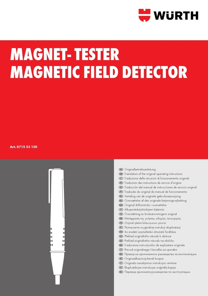
MULTI-TESTER PRO II LED
Art. 0715 53 165

2
DE ........................ 4 – 9
GB ........................ 10 – 15
IT ........................ 16 – 21
FR ........................ 22 – 27
ES ........................ 28 – 33
PT ........................ 34 – 39
NL ........................ 40 – 45
DK ........................ 46 – 51
NO ........................ 52 – 57
FI ........................ 58 – 63
SE ........................ 64 – 69
GR ........................ 70 – 75
TR ........................ 76 – 81
PL ........................ 82 – 87
HU ........................ 88 – 93
CZ ........................ 94 – 99
SK ........................ 100 – 105
RO ........................ 106– 111
SI ........................ 112– 117
BG ........................ 118– 123
EE ........................ 124– 129
LT ........................ 130– 135
LV ........................ 136– 141
RU ........................ 142– 147
HR ........................ 148– 153
RS ........................ 154– 159

FI
RCD
LH
FI
RCD
2
3
3
1
4
5
2
7
4
6
3
I

4
Zu Ihrer Sicherheit
DE
Lesen Sie vor der ersten
Benutzung Ihres Gerätes diese
Betriebsanleitung und handeln
Sie danach. Bewahren Sie diese
Betriebsanleitung für späteren Gebrauch
oder für Nachbesitzer auf.
■Vor erster Inbetriebnahme Sicherheitshinweise
unbedingt lesen!
■Bei Nichtbeachtung der Betriebsanleitung und der
Sicherheitshinweise können Schäden am Gerät und
Gefahren für den Bediener und andere Personen
entstehen.
Verbot eigenmächtiger Veränderungen
und Umbauten
Es ist verboten, Veränderungen am Gerät durchzufüh-
ren oder Zusatzgeräte herzustellen. Solche Änderungen
können zu Personenschäden und Fehlfunktionen führen.
■Reparaturen am Gerät dürfen nur von hierzu be-
auftragten und geschulten Personen durchgeführt
werden. Hierbei stets die Originalersatzteile der
Adolf Würth GmbH & Co. KG verwenden. Damit
wird sichergestellt, dass die Sicherheit des Gerätes
erhalten bleibt.
Zeichen und Symbole dieser Anleitung
Die Zeichen und Symbole in dieser Anleitung sollen
Ihnen helfen, die Anleitung und die Maschine schnell
und sicher zu benutzen.
Hinweis
Informiert Sie über die eektivste bzw.
praktikabelste Nutzung des Gerätes und
dieser Anleitung.
■Handlungsschritte
Die denierte Abfolge der Handlungsschritte
erleichtert Ihnen den korrekten und sicheren
Gebrauch.
3Ergebnis
Hier nden Sie das Ergebnis einer Abfolge von
Handlungsschritten beschrieben.
Gefahrenstufen von Warnhinweisen
In dieser Betriebsanleitung werden die folgenden
Gefahrenstufen verwendet, um auf potenzielle Gefah-
rensituationen und wichtige Sicherheitsvorschriften
hinzuweisen:
GEFAHR !
Die gefährliche Situation steht
unmittelbar bevor und führt, wenn die
Maßnahmen nicht befolgt werden,
zu schweren Verletzungen bis hin
zum Tod. Befolgen Sie unbedingt die
Maßnahme.
WARNUNG !
Die gefährliche Situation kann eintreten
und führt, wenn die Maßnahmen
nicht befolgt werden, zu schweren
Verletzungen bis hin zum Tod. Arbeiten
Sie äußerst vorsichtig.
VORSICHT !
Die gefährliche Situation kann
eintreten und führt, wenn die
Maßnahmen nicht befolgt werden,
zu leichten oder geringfügigen
Verletzungen.
Achtung !
Eine möglicherweise schädliche Situation kann
eintreten und führt, wenn sie nicht gemieden wird,
zu Sachschäden.
Aufbau von Sicherheitshinweisen
GEFAHR !
Art und Quelle der Gefahr!
ÂFolgen bei Nichtbeachtung
¾Maßnahme zur Gefahrenabwehr

5
Der Spannungsprüfer muss
kurz vor dem Einsatz auf
Funktion geprüft werden.
Vergewissern Sie sich, dass
Messleitungen und Gerät in
einwandfreiem Zustand sind.
■Überprüfen Sie das Gerät an einer bekannten
Spannungsquelle , z. B. 230 V-Steckdose.
■Fällt hierbei die Anzeige einer oder mehrerer
Funktionen aus, darf das Gerät nicht mehr ver-
wendet werden und muss vom Fachpersonal
überprüft werden.
■Stromschlag kann zum Tod oder zu schweren
Verletzungen von Personen führen sowie eine
Gefährdung für die Funktion von Gegen-
ständen (z. B. die Beschädigung des Gerätes)
sein.
■Bitte beachten Sie die fünf Sicherheitsregeln:
1. Freischalten
2. Gegen Wiedereinschalten sichern
3. Spannungsfreiheit feststellen (Spannungs-
freiheit ist 2-polig festzustellen)
4. Erden und kurzschließen
5. Benachbarte unter Spannung stehende Tei-
le abdecken
■Richten Sie das LED-Licht nie direkt oder
indirekt durch reektierende Oberächen auf
das Auge.
■Vermeiden Sie einen Betrieb des Gerätes in
der Nähe von elektrischen Schweißgeräten,
Induktionsheizern und anderen elektromagne-
tischen Feldern.
■Nach abrupten Temperaturwechseln muss das
Gerät vor dem Gebrauch zur Stabilisierung
ca. 30 Minuten an die neue Umgebungstem-
peratur angepasst werden.
■Bei niedrigen Temperaturen unter 5 °C
kann die Bereitschaft des Spannungsprüfers
beeinträchtigt werden. Sorgen Sie für eine
ausreichende Stromversorgung. Verwenden
Sie Batterien, die für solche Temperaturbe-
reiche speziziert sind.
■Setzen Sie das Gerät nicht längere Zeit hohen
Temperaturen aus.
■Vermeiden Sie staubige und feuchte Umge-
bungsbedingungen.
■Messgeräte und Zubehör sind kein Spielzeug
und gehören nicht in Kinderhände!
■In gewerblichen Einrichtungen sind die Un-
fallverhütungsvorschriften des Verbandes der
gewerblichen Berufsgenossenschaften für elekt-
rische Anlagen und Betriebsmittel zu beachten.
■Gerät nur an den Handgrien anfassen, ver-
meiden Sie die Berührung der Prüfspitzen!
■Prüfungen auf Spannungsfreiheit immer nur
zweipolig durchführen!
■Nicht mit oenem Batteriefach benutzen!
Die Messleitungen müssen während eines Bat-
teriewechsels vom Messkreis entfernt werden.
■Eine einwandfreie Anzeige ist im Temperatur-
bereich von -15 °C bis + 45 °C sichergestellt.
■Das zusätzlich anzeigende Warnsymbol und
Vibration bei Spannungen > 35 V dienen nur
zur Warnung von lebensgefährlichen Span-
nungen, nicht zur Messung.
■Den Warnton vor Prüfungen mit Umgebungs-
lautstärke auf Hörbarkeit prüfen.
■Batterien sofort wechseln, wenn beim Ein-
schalten ein dauerhaftes Warnsignal ertönt
oder das Gerät sich schon beim Einschalten
sofort wieder abschaltet.
■Um das Gerät vor Beschädigung zu schützen,
entfernen Sie bitte bei längerem Nichtge-
brauch des Gerätes die Batterien.
■Verwenden Sie die verschiedenen ange-
zeigten Signale des Gerätes einschließlich des
ELV-Grenzwertes nicht für Messzwecke.
■Ein Spannungsprüfer mit relativ niedriger
Impedanz wird im Vergleich zum Referenzwert
von 100 kΩ nicht alle Störspannungen mit
einem Ursprungswert oberhalb ELV anzeigen.
Bei Kontakt mit den zu prüfenden Anlagen-
teilen kann der Spannungsprüfer die Störspan-
nungen durch Entladung vorübergehend bis
zu einem Pegel unterhalb ELV herabsetzen.
Nach dem Entfernen des Spannungsprüfers
wird die Störspannung ihren Ursprungswert
wieder annehmen.
Sicherheitshinweise

6
Bestimmungsgemäße
Verwendung
Es können Gleichspannungen von 6 V bis 1400 V
und Wechselspannungen von 6 V bis 1000 V
gegen Erde geprüft werden.
Ebenso können Polaritäts-, Drehfeldrichtungs- und
Durchgangsprüfungen bis 200 kΩ sowie FI/RCD-
Tests durchgeführt werden.
Multi-Tester Pro-LED ist durch die hohe Schutzart
(IP65) auch bei rauem Einsatz verwendbar.
Der Einsatz des Gerätes ist durch Elektrofachkräfte
und durch fachkundiges Personal vorgesehen.
Jeder darüber hinausgehende Gebrauch gilt als
nicht bestimmungsgemäß.
Für Schäden bei nicht bestimmungsgemä-
ßer Verwendung haftet der Benutzer und
jegliche Garantie- und Gewährleistungs-
ansprüche gegenüber dem Hersteller
verfallen.
Gerätekennwerte
Art. 0715 53 165
Anzeige 16 LEDs für Spannung
(12, 24, 48, 120, 230,
400, 690 und 1000 V),
Polarität (+~-), Durchgang
(Rx/Ω) und Phase/Dreh-
feld (R/L) ELV
Nennspannungs-
bereich 6 ... 1000 V AC
6 ... 1400 V DC
Indikation 0,85 Un
Frequenzbereich 0,16 ... 500 Hz
Schaltbare Last 30 mA bei 230 V
Einschaltdauer 30 s an/240 s aus
Nominaler Strom IN< 3,5 mA
Spitzenstrom IS< 0,3 A bei gedrückten
Tasten (FI/RCD)
Phasenprüfung Pol > 100 V AC
Schutzklasse II
Impedanz 625 kΩ / 5 kΩ bei ELV-
Wechselspannung
Durchgangsprüfung 0 ... 200 kΩ
Klimakategorie N normal
Betriebstemperatur -15 °C bis +45 °C, bei
> 95 % bis +31 °C
Schutzart IP 65
■Ein Spannungsprüfer mit relativ hoher innerer
Impedanz wird im Vergleich zum Referenzwert
von 100 kΩ bei vorhandener Störspannung
"Betriebsspannung nicht vorhanden" nicht
eindeutig anzeigen.
■Wenn die Anzeige "Spannung vorhanden"
nicht erscheint, wird dringend empfohlen, vor
Aufnahme der Arbeiten die Erdungseinrich-
tung einzulegen.
■Wenn die Anzeige "Spannung vorhanden"
bei einem Teil erscheint, der als von der
Anlage getrennt gilt, wird dringend empfohlen
mit zusätzlichen Maßnahmen den Zustand
"Betriebsspannung nicht vorhanden" des zu
prüfenden Anlagenteils nachzuweisen und
festzustellen, dass die vom Spannungsprüfer
angezeigte Spannung eine Störspannung ist.
■Nur Original Würth- Zubehör und
Ersatzteile verwenden.
Sicherheitshinweise

7
Art. 0715 53 165
Überspannungs-
kategorie CAT IV 1000 V
Prüfnorm EN 61234-3:2014
Spannungsversorgung 2 x 1,5 V Typ AAA Micro
Art. 0827 111
Geräteelemente
Übersicht (Abb. I)
1 Prüfspitze L1
2 Mechanische Markierungen
3 FI/RCD-Tasten
4 Handgrie
5 Prüfspitzen L2
6 LED-Anzeigen
7 LH-Taste
Bedienung
Hinweis
Verwenden Sie die ELV-LED nicht für
Messzwecke!
Hinweis
Spannungen haben Priorität. Liegt
keine Spannung an den Prüfspitzen
an (< 4 V), bendet sich das Gerät
im Modus Durchgangsprüfung. Im
Stand-by Zustand leuchtet die orange
LED "Rx/Ω".
■Um das Gerät einzuschalten, halten Sie die
Prüfspitzen kurz aneinander.
3Alle optischen Anzeigen des Gerätes leuchten auf.
3Das Gerät wechselt in die Durchgangsprüfung.
Selbsttest
■Halten Sie zum Test die Prüfspitzen aneinander.
3Die „Rx/Ω“- LED muss deutlich grün leuchten.
■Wenn die LED nicht oder nur schwach leuchtet,
setzen Sie neue Batterien ein.
■Wenn das Gerät trotz neuer Batterien nicht
funktioniert, lassen Sie es von Fachpersonal
überprüfen.
Nach kurzer Zeit schaltet das Gerät automatisch
durch die „Auto Power O“-Funktion ab.
3Die orangene „Rx/Ω“- LED geht aus.
Gleichspannung prüfen
■Halten Sie die Prüfspitzen an eine Gleichspan-
nung innerhalb des Nennspannungsbereichs.
3Eine der unteren (12 V +~-) sowie die darüber
angeordneten LEDs, entsprechend der anliegen-
den Spannung, leuchten auf.
3Die unteren LEDs zeigen die Polarität gemäß der
Kennzeichnung an den Prüfspitzen an! (+, -)
3Bei Überschreitung des Schwellenwertes von
35 V ertönt ein Signalton und die ELV-LED leuch-
tet auf. Dies signalisiert ein Anliegen lebensbe-
drohlicher Spannung!
Wechselspannung prüfen
■Halten Sie die Prüfspitzen an eine Wechselspan-
nung innerhalb des Nennspannungsbereichs.
3Beide der unteren (12 V +~-) sowie die darüber
angeordneten LEDs, entsprechend der anliegen-
den Spannung, leuchten auf.
3Das gleichzeitige Aueuchten der unteren LEDs
weist auf Wechselspannung hin (~).
3Bei Überschreitung des Schwellenwertes von
35 V ertönt ein Signalton und die ELV-LED leuch-
tet auf. Dies signalisiert ein Anliegen lebensbe-
drohlicher Spannung!
Phasenprüfung
■Berühren Sie mit der Testspitze „L2“ einen Leiter.
3Bei Anliegen einer Phase von min. 100 V~
leuchtet die „<L“-LED auf!
Für die Bestimmung der Phasenleiter kann die Wahr-
nehmbarkeit der Anzeige beeinträchtigt werden,
z. B. durch isolierende Vorrichtungen zum Schutz
gegen direktes Berühren, in ungünstigen Positionen,
z. B. auf Holzleitern oder isolierenden Fußbodenbe-
lägen, einer nicht geerdeten Spannung oder auch
bei ungünstigen Lichtverhältnissen.
Sie können Phasen auch ermitteln, indem Sie die
Außenleiter gegen den Schutzleiter prüfen. Beim
Phasenleiter sollte die anliegende Spannung ange-
zeigt werden.
Hinweis
Achten Sie darauf, dass bei dieser
Prüfung ein zusätzlicher Strom über
den Schutzleiter ießt. Dieser addiert
sich zu dem bereits vorliegenden Strom
und könnte den Schutzschalter (FI)
auslösen!

8
Drehfeldprüfung (max. 400 V)
■Umfassen Sie vollächig die Grie L1 und L2.
■Legen Sie die Prüfspitzen L1 und L2 an zwei
Außenleiter (Phasen).
■Prüfen Sie, ob die Außenleiterspannung von
z. B. 400 V anliegt.
3Eine Rechtsdrehfolge {Phase L 1 vor Phase L2)
ist gegeben, wenn die "R" LED aueuchtet.
3Eine Linksdrehfolge (Phase L2 vor Phase L1) ist
gegeben, wenn die "L" LED aueuchtet.
Der Drehfeldbestimmung muss immer eine Prüfung
mit vertauschten Prüfspitzen erfolgen. Dabei muss
sich die Drehrichtung ändern.
Hinweis
Die Drehfeldprüfung ist ab 200 V,
50/60 Hz (Phase gegen Phase) im
geerdeten Drehstromnetz möglich.
Einhandprüfung
Die beiden Handteile können arretiert werden
(Abstandshalter an der Messleitung).
Durch einfaches Drehen ist der Abstand der Mess-
spitzen einstellbar. ( Schuko/CEE)
Prüfstellenbeleuchtung
■Um die Prüfstellenbeleuchtung ein- bzw. auszu-
schalten, drücken Sie die L.H-Taste.
Durchgangsprüfung
■Legen Sie die Prüfspitzen an die zu prüfende
Leitung, Sicherung o.ä. an.
3Bei einem Widerstand von 0-200 kΩ leuchtet
die grüne „Rx/Ω“-LED auf.
FI/RCD-Auslösetest, PE (
Schutzleitertest
)
WARNUNG !
Hoher Stromuss
ÂEin Test an beweglichen und
nicht fest verdrahteten Geräten,
Verlängerungsleitungen etc. kann im
Fehlerfall zu einem hohen Stromfluss
an den mit Schutzleiter verbundenen
Metallteilen kommen!
¾Führen Sie den FI/RCD-Test nur
an fest installierten Anlagen und
Stromkreisen durch.
■Um Störungen und induktive sowie kapazitive
Kopplungen bei der Spannungsprüfung zu
verringern, drücken Sie gleichzeitig beide FI/
RCD-Tasten.
3Eine geringere Impedanz wird eingeschaltet.
3Der Spitzenstrom liegt unterhalb 0,3 A (IS).
3Der zusätzliche Lastkreis ist überlastgeschützt
und reduziert den Laststrom nach einigen
Sekunden.
Diese eingebaute Last ermöglicht es, einen FI/RCD-
Schutzschalter auszulösen. Geprüft wird der FI/
RCD (max. 30 mA 230 V AC) zwischen Phase und
Schutzleiter.
■Halten Sie eine Prüfspitze an einen phasenfüh-
renden Leiter.
■Halten Sie die andere Prüfspitze an den Schutz-
leiter.
■Drücken Sie beide FI/RCD-Tasten so tief wie
möglich.
Hinweis
Ohne Drücken der beiden FI/RCD-
Tasten wird der Schutzschalter im
Normalfall nicht ausgelöst.
Wartung / Pege
■Das Gerät immer trocken und sauber halten.
Das Gerät darf mit einem feuchten Tuch gerei-
nigt werden.
Batteriewechsel
Wenn die Batterien sich entleert haben, ertönt ein
Warnsignal und das Gerät schaltet sich aus.
■Lösen Sie die Schrauben am Batteriefach am
Hauptgehäuse.
■Önen Sie das Batteriefach.
■Wechseln Sie Batterien. Achten Sie beim
Einsetzen der neuen Batterien auf die richtige
Polarität.
■Verschließen und verschrauben Sie das Batte-
riefach.
■Entsorgen Sie die leeren Batterien umweltge-
recht.

9
Umwelthinweise
Werfen Sie das Gerät keinesfalls in
den normalen Hausmüll. Entsorgen
Sie das Gerät über einen zugelasse-
nen Entsorgungsbetrieb oder über
Ihre kommunale Entsorgungseinrich-
tung. Beachten Sie die aktuell
geltenden Vorschriften. Setzen Sie
sich im Zweifelsfall mit Ihrer Entsorgungseinrichtung
in Verbindung. Führen Sie alle Verpackungsmateria-
lien einer umweltgerechten Entsorgung zu.
Akkus/Batterien:
Werfen Sie Akkus/Batterien nicht in den Hausmüll,
ins Feuer oder ins Wasser. Akkus/Batterien sollen
gesammelt, recycelt oder auf umweltfreundliche
Weise entsorgt werden.
Gewährleistung
Für dieses Würth Gerät bieten wir eine Gewährleis-
tung gemäß den gesetzlichen/länderspezischen
Bestimmungen ab Kaufdatum (Nachweis durch
Rechnung oder Lieferschein).
Entstandene Schäden werden durch Ersatzlieferung
oder Reparatur beseitigt. Schäden, die auf unsach-
gemäße Behandlung zurückzuführen sind, sind von
der Gewährleistung ausgeschlossen.
Beanstandungen können nur anerkannt werden,
wenn das Gerät unzerlegt einer Würth Niederlas-
sung, Ihrem Würth Außendienstmitarbeiter oder
einer Würth autorisierten Kundendienststelle über-
geben wird.
Technische Änderungen vorbehalten.
Für Druckfehler übernehmen wir keine Haftung.
Ersatzteile
Sollte das Gerät trotz sorgfältiger Herstell- und
Prüfverfahren einmal ausfallen, ist die Reparatur von
einem Würth masterService® ausführen zu lassen.
In Deutschland erreichen Sie den
Würth masterService® kostenlos unter Tel.
0800-WMASTER (0800-9 62 78 37).
In Österreich unter der Tel. 0800-20 30 13.
Bei allen Rückfragen und Ersatzteilbestellungen bitte
unbedingt die Artikelnummer laut Typenschild des
Gerätes angeben.
Die aktuelle Ersatzteilliste dieses Gerätes kann im
Internet unter „http://www.wuerth.com/partsma-
nager“ aufgerufen oder von der nächstgelegenen
Würth Niederlassung angefordert werden.
Konformitätserklärung
Das Produkt erfüllt die aktuellsten Richtlinien.
Nähere Informationen erhalten Sie auf www.wuerth.
com.
Wir erklären in alleiniger Verantwortung, dass
dieses Produkt mit den folgenden Normen oder
normativen Dokumenten übereinstimmt:
Normen
• EN 61234-3:2014
gemäß den Bestimmungen der Richtlinien:
EU-Richtlinie
• 2014/35/EU
• 2014/30/EU
• 2011/65/EU
• 2012/19/EU
Technische Unterlagen bei:
Adolf Würth GmbH & Co. KG,
Reinhold-Würth-Straße 12 – 17,
74653 Künzelsau, Germany
F. Wolpert Dr.-Ing. S. Beichter
Prokurist – Leiter
Produktmanagement Prokurist
Leiter Qualität
Künzelsau: 14.12.2016

10
For Your Safety
GB
Please read and comply with
these operating instructions
prior to initial operation of
your device. Keep these operating
instructions for later use or for a
subsequent owner.
■Prior to rst use always read the safety
instructions!
■Failure to observe the instruction manual and
the safety instructions could result in damage
to the device and danger for the operator and
others.
Unauthorised modifications and
conversions are not permitted
Modication of the device or manufacturing of
additional devices is not permitted. Such modica-
tions can result in personal injury or malfunctions.
■Only appointed and trained personnel may
carry out repairs to the device. For such pur-
poses, always use original spare parts from
Adolf Würth GmbH & Co. KG. This will ensure
the continuing safe operation of the device.
Signs and symbols in these instructions
The signs and symbols in these instructions should
help you to use the instructions and the machine
quickly and safely.
Note
Provides information on the most
eective or most practical use of the
device and these instructions.
■Handling steps
The dened sequence of handling steps facili-
tates correct and safe use of the device.
3Result
This is where the result of a handling step
sequence is described.
Warning instruction hazard levels
The following hazard levels are used in these oper-
ating instructions to indicate potentially hazardous
situations and important safety rules:
The hazardous situation is about to
occur and will lead to severe injuries
or even death if the measures are
not observed. Observe the measure
without fail.
The hazardous situation could occur
and will lead to severe injuries and
even death if the measures are not
observed. Work with extreme care.
The hazardous situation could occur
and will lead to slight or minor injuries
if the measures are not observed.
Attention!
Apossibly harmful situation could occur and will
lead to property damage if not avoided.
Format of safety instructions
Type and source of the danger!
ÂConsequences of non-observance
¾Danger prevention measure

11
The proper function of the
voltage tester must be
checked shortly before use.
Ensure that measuring lines
and device are in proper
working order.
■Check the device by connecting it to a known
power source, e.g. a 230 V socket.
■If the display for one or more functions fails
in the process, the device must no longer
be used and must be checked by qualied
specialist personnel.
■Electric shock may result in major injuries or
death and may endanger the functionality of
objects (e.g. damage to the device).
■Read and comply with the ve safety rules:
1. Disconnect mains
2. Prevent reconnection
3. Test absence of voltage by approved
means (establish absence of voltage using
two-pole voltage indicators)
4. Earthing and short-circuiting
5. Protect adjacent live parts using covers
■Never direct the LED light, directly or indirectly
from reecting surfaces, towards the eye.
■Avoid operating the device in the vicinity of
electric welding machines, induction heaters
and other electromagnetic elds.
■After abrupt changes in temperature, the
device must be allowed to adapt to the new
ambient temperature and stabilise for approx.
30 minutes.
■At low temperatures below 5 °C, the oper-
ability of the voltage tester can be impaired.
Ensure there is an adequate power supply.
Use batteries that are specied for such tem-
perature ranges.
■Do not expose the device to high temperatures
for any length of time.
■Avoid dusty and humid ambient conditions.
■Measurement devices and accessories are not
toys and should always be kept away from
children!
■In commercial facilities the accident preven-
tion regulations (in Germany issued by the
commercial trade association for the safety
of electrical systems and equipment) must be
observed.
■Hold the device only at the handles, avoid
touching the test probes!
■Always test absence of voltage at only two
terminals!
■Do not use with the battery compartment open!
The measuring leads must be disconnected
from the measuring circuit during battery
replacement.
■A correct display is ensured within the tem-
perature range of -15°C to +45°C.
■The additionally displayed warning symbol
and vibration at voltages > 35 V are intended
only as a warning of potentially fatal voltages,
not for measurement.
■Check the warning signal for audibility in loud
working environments before starting tests.
■Replace the batteries immediately if a contin-
uous warning signal sounds when switching
on or if the device immediately switches o
again when switching on.
■In order to protect the device from damage,
remove the batteries if the device is not in use
for a prolonged period of time.
■Do not use the various displayed signals of
the device including the ELV limit value for
measurement purposes.
■A voltage tester with relatively low impedance
will not in comparison with the reference value
of 100 kΩ display all disturbance voltages
with an original value above ELV. Upon
contact with the system parts to be tested,
the voltage tester can temporarily lower the
interference voltages by discharging to a level
below ELV. After removal of the voltage tester,
the interference voltage will again adopt its
original value.
Safety instructions

12
Intended use
DC voltages from 6 V to 1400 V and AC voltages
from 6 V to 1000 V can be measured relative to
earth.
Likewise polarity, phase sequence and continuity
checks up to 200 kΩ as well as RCD tests can be
performed.
Thanks to its high protection class (IP65), Multi-Tester
Pro-LED can be used even under tough operating
conditions.
The device is only intended for use by electricians
and qualied personnel.
Any other use is considered an improper use.
The user alone is responsible for damage
resulting from improper use while any
warranty claims against the manufacturer
will likewise become invalid.
Technical Data
Parameter 0715 53 165
Display 16 LEDs for voltage (12,
24, 48, 120, 230, 400,
690 and 1000 V), polari-
ty (+~-), continuity (Rx/Ω)
and phase/rotary eld
(R/L) +ELV
Nominal voltage 6 ... 1000 V AC
6 ... 1400 V DC
Indication 0.85 Un
Frequency range 0.16 ... 500 Hz
Switchable load 30 mA at 230 V
Cyclic duration factor 30 s ON/240 s OFF
Rated current IN< 3.5 mA
Peak current IP< 0.3 A with button
pressed (FI/RCD)
Phase check pole > 100 V AC
Protection class II
Impedance 625 kΩ / 5 kΩ for ELV
AC voltage
Continuity test 0 ... 200 kΩ
Climatic category N normal
Operating tempera-
ture -15 °C to +45 °C, at
> 95 % to +31 °C
Degree of protection IP 65
Overvoltage category CAT IV 1000 V
■A voltage tester with relatively high internal
impedance will not in comparison with the
reference value of 100 kΩ unequivocally
display “Operating voltage not present” if an
interference voltage is present.
■If the indication “Voltage present” does not
appear, it is highly recommended that before
commencing work the earthing device is
inserted.
■If the indication “Voltage present” appears
with a part that is classed as disconnected
from the system, it is highly recommended that
additional measures are taken to achieve the
status “Operating voltage not present” for
the system part under test and to demonstrate
and identify that the voltage displayed by the
voltage tester is an interference voltage.
■Use only genuine Würth accessories
and spare parts.
Safety instructions

13
Parameter 0715 53 165
Test standard EN 61243-3:2014
Power supply 2 x 1.5 V type AAA Micro
Item 0827 111
Device elements
Overview [Fig. I]
1 Test probe L1
2 Mechanical markings
3 FI/RCD buttons
4 Handles
5 Test probe L2
6 LED indicators
7 LH button
Operation
Note
Do not use the ELV LED for measure-
ment purposes!
Note
Voltages have priority. If there is no volt-
age at the test probes (< 4 V), the device
is in continuity check mode. In stand-by
mode the orange LED "Rx/Ω" is lit.
■To switch the device on, hold both test probes
together.
3All optical displays of the device light up.
3The device switches to continuity check.
Self-test
■Touch the test probes together for this test.
3The "Rx/Ω" LED must clearly light up green.
■If the LED does not light up or only lights up
weakly, insert new batteries.
■If the device does not function even with new
batteries, it must be checked by a specialist
technician.
After a short time the device switches o automati-
cally due to the "Auto Power O" function.
3The orange “Rx/Ω” LED goes out.
Check DC voltage
■Hold the test probes in contact with a DC
voltage that is within the nominal voltage range.
3One of the lower LEDs (12 V +~-) and the LEDs
above it light up, corresponding to the voltage
that is present.
3The lower LEDs indicate the polarity according
to the markings on the test probes! (+, -)
3When the threshold value of 35 V is exceeded,
a signal tone sounds and the ELV LED comes on.
This signals the presence of a potentially fatal
voltage!
AC voltage check
■Hold the test probes in contact with an AC
voltage that is within the nominal voltage range.
3Both of the lower LEDs (12 V +~-) and the LEDs
above it light up, corresponding to the voltage
that is present.
3The simultaneous lighting up of the lower LEDs
indicates an AC voltage (~).
3When the threshold value of 35 V is exceeded,
a signal tone sounds and the ELV LED comes on.
This signals the presence of a potentially fatal
voltage!
Phase check
■Touch a conductor with test probe "L2".
3On contact with a phase of min. 100 V~, the
"<L" LED lights up!
For determination of the phase conductor, the per-
ceptibility of the display may be impaired, e.g. by
insulating devices for protection against accidental
direct contact, in unfavourable positions, for exam-
ple on wooden ladders or insulating oor coverings,
a non-earthed voltage or under unfavourable light
conditions.
You can also determine the phases by checking the
phase conductor relative to the protective conduc-
tor. If the phase conductors is checked the voltage
present should be indicated.
Note
Recall that in this test an additional
current ows along the protective
conductor. This is added to an already
existing current and could trigger the
circuit breaker (RCD)!

14
Phase sequence (rotary field) check
(max. 400 V)
■Fully grip handles L1 and L2.
■Hold test probes L1 and L2 against two outer
conductors (phases).
■Check whether the phase voltage of e.g. 400 V
is present.
3A clockwise rotating eld (phase L1 before phase
L2) is indicated when the "R" LED lights up.
3An anti-clockwise rotating eld (phase L2 before
phase L1) is indicated when the "L" LED lights up.
The rotary eld check must always be repeated with
reversed test probes. The direction of rotation must
thereby change.
Note
The rotary eld check can be
performed above 200 V, 50/60 Hz
(phase relative to phase) in the earthed
3-phase AC grid.
Single-handed check
The two handpieces can be locked (spacer on the
measuring lead).
The distance between the test probes can be
adjusted simply by turning. (Schuko/CEE plug)
Test point light
■To switch the test point light on or o, press the
L.H. key.
Continuity test
■Place the test probes against the lead, fuse, etc.
to be tested.
3At a resistance of 0 - 200 kΩ, the green "Rx/Ω"
LED lights up.
FI/RCD trip test, PE (protective earth test)
High current ow
ÂTesting on moving and not perma-
nently wired devices, extension leads,
etc. can, in the event of a fault, result
in a high current in metallic parts con-
nected to the protective conductor!
¾Only perform an RCD test on xed
installed systems and circuits.
■To reduce interference eects, inductive and ca-
pacitive couplings during voltage testing, press
both FI/RCD buttons simultaneously.
3A lower impedance is switched on.
3The peak current is below 0.3 A (IP).
3The additional load circuit is overload protect-
ed and reduces the load current after a few
seconds.
This integral load makes it possible to trigger an RCD
circuit breaker. The RCD (max. 30 mA 230 V AC) is
tested between phase and protective conductor.
■Hold a test probe against one phase conductor.
■Hold the other test probe against the protective
conductor.
■Press both FI/RCD buttons in as far as possible.
Note
Under normal circumstances the circuit
breaker is not normally triggered
without both the FI/RCD buttons being
pressed.
Maintenance / Care
■Keep the device always dry and clean. The
device may be cleaned using a damp cloth.
Battery changing
If the batteries have become discharged, a warning
signal sounds and the device switches o.
■Undo the battery compartment screws on the
main housing.
■Open the battery compartment.
■Change the batteries. Ensure the new batteries
are inserted with the correct polarity.
■Close the battery compartment and screw the
lid in place.
■Dispose of the empty batteries in an environmen-
tally compatible manner.

15
Environmental Instructions
Do not throw the device away with
normal domestic waste. Dispose of
the device via an approved waste
disposal company or via your local
authority waste disposal facility.
Observe the currently valid regula-
tions. In case of doubt, contact your
waste disposal facility. Dispose of all packaging in
an environmentally compatible manner.
Batteries:
Do not dispose of batteries with domestic waste,
do not expose to re or water. Collect and recy-
cle batteries or dispose of with due care for the
environment.
Warranty
We provide a warranty for this Würth device from
the date of purchase and in accordance with the
legal/country-specic regulations (proof of pur-
chase through invoice or delivery note).
Damage that has occurred will be corrected either
by replacement or by repair. Damage caused by
improper handling is not covered by the warranty.
Claims under warranty can only be accepted if
the device is returned fully assembled to a Würth
agency, your Würth sales representative or an
authorised Würth customer service workshop.
Subject to technical changes without prior notice.
We accept no liability for printing errors.
Spare parts
If, despite careful manufacturing and testing pro-
cesses, the device should become faulty, have the
repair carried out by a Würth masterService®
station.
With any enquiries or spare parts orders, always
quote the article number as given on the device
type plate. The latest spare parts list for the device is
available online at http://www.wuerth.com/parts-
manager. Alternatively, contact your local Würth
agency for a hardcopy.
Declaration of Conformity
The product meets the requirements of the latest
directives. You can obtain more detailed information
at www.wuerth.com.
We declare under our sole responsibility that this
product conforms to the following standards and
directives:
Standards
• EN 61243-3:2014
in accordance with the regulations stipulated in the
directives:
EU directive
• 2014/35/EU
• 2014/30/EU
• 2011/65/EU
• 2012/19/EU
Technical documentation at:
Adolf Würth GmbH & Co. KG,
Reinhold-Würth-Straße 12 – 17,
74653 Künzelsau, Germany
F. Wolpert Dr.-Ing. S. Beichter
Head of Product Man-
agement
Authorised Signatory
Head of Quality,
Authorised Signatory
Künzelsau: 14/12/2016

16
Informazioni per la sicurezza
IT
Prima di utilizzare l'apparec-
chio per la prima volta,
leggere e seguire queste
istruzioni per l'uso. Conservare
le presenti istruzioni per l'uso per
consultarle in un secondo tempo o
per consegnarle a successivi
proprietari.
■Prima di mettere in funzione l'apparecchio
per la prima volta leggere attentamente le
Avvertenze di sicurezza.
■La mancata osservanza delle istruzioni d'uso
e delle norme di sicurezza può causare danni
all'apparecchio e presentare pericoli per
l'utente e le altre persone.
Divieto di modifiche e conversioni
arbitrarie
Vietato apportare modiche all'apparecchio o
installare dispositivi aggiuntivi. Tali modiche pos-
sono portare a danni alle persone e ad anomalie
di funzionamento.
■I lavori di riparazione sul dispositivo possono
essere eseguiti solo da personale incaricato
e con adeguata formazione. Per questi lavori
utilizzare sempre i pezzi di ricambio originali
della Adolf Würth GmbH & Co. KG. In questo
modo è garantita la sicurezza dell'apparec-
chio.
Segnali e simboli contenuti nelle
istruzioni per l'uso
I segnali e i simboli contenuti nelle presenti istru-
zioni per l'uso dovrebbero contribuire all'utilizzo
rapido e corretto delle istruzioni e della macchina.
Nota
Fornisce suggerimenti sull'utilizzo più
ecace e pratico dell'apparecchio e
delle istruzioni.
■Fasi operative
La sequenza denita delle fasi operative
permette un utilizzo corretto e sicuro.
3Risultato
Qui viene descritto il risultato di una sequenza
di fasi operative.
Livelli di pericolo delle avvertenze
In queste istruzioni per l'uso vengono utilizzati i
seguenti livelli di pericolo per segnalare potenziali
situazioni di pericolo e disposizioni di sicurezza
importanti:
PERICOLO!
La situazione pericolosa è imminente
e, in caso di mancata osservanza
delle disposizioni, causa lesioni gravi
o mortali. Osservare assolutamente le
disposizioni.
Èpossibile che si verichi una
situazione pericolosa che, in caso di
mancata osservanza delle disposizioni,
può causare lesioni gravi o mortali.
Lavorare con la massima prudenza.
ATTENZIONE!
Èpossibile che si verichi una
situazione pericolosa che, in caso
di mancata osservanza delle
disposizioni, può causare lesioni lievi
o limitate.
Avviso!
Èpossibile che si verichi una situazione
potenzialmente pericolosa che, se non evitata,
può causare danni materiali.
Organizzazione delle avvertenze di
sicurezza
PERICOLO!
Tipo e fonte di pericolo.
ÂConseguenze in caso di mancata
osservanza
¾Disposizione per rafforzamento
della sicurezza

17
Prima di mettere in funzione il
tester, controllarne il funzio-
namento. Accertarsi che i
puntali e il dispositivo siano in
perfette condizioni.
■Controllare l'apparecchio su una fonte di
tensione nota, p. es. una presa da 230 V.
■Se durante questo controllo manca la visua-
lizzazione di una o più funzioni, il dispositivo
non deve essere più usato e deve essere
controllato da personale specializzato.
■La scossa elettrica può comportare il decesso
o lesioni gravi per le persone e rischi per la
funzionalità degli oggetti (p. es. può danneg-
giare l'apparecchio).
■Si prega di rispettare le cinque regole per la
sicurezza:
1. Distacco della tensione
2. Protezione contro la riaccensione
3. Controllo dell'assenza di tensione (da con-
trollare sui 2 poli)
4. Collegamento a massa e cortocircuito
5. Coprire i pezzi vicini posti sotto tensione
■Non rivolgere mai la luce a LED direttamente
verso gli occhi o indirettamente attraverso
superci riettenti.
■Non mettere in funzione il dispositivo nei
pressi di saldatrici elettriche, riscaldamenti ad
induzione o di altri campi elettromagnetici.
■Dopo un brusco cambio di temperatura,
l'apparecchio, prima dell'uso per la stabilizza-
zione, deve essere adattato per ca. 30 minuti
alla nuova temperatura ambientale.
■A basse temperature sotto i 5 °C la dispo-
nibilità del tester può essere compromessa.
Assicurarsi che l'alimentazione di corrente sia
suciente. Utilizzare batterie con speciche
adatte a tali temperature.
■Non esporre il dispositivo ad elevate tempera-
ture per un periodo prolungato.
■Evitare condizioni ambientali con polveri e umidità.
■Gli strumenti di misura e gli accessori non
sono giocattoli e non devono essere alla
portata dei bambini.
■Negli allestimenti industriali, rispettare le pre-
scrizioni antinfortunistiche dell'associazione
professionale degli industriali per gli impianti e
i mezzi di esercizio elettrici.
■Tenere il dispositivo solo per le impugnature
ed evitare di toccare i puntali di prova.
■Controllare l'assenza di tensione sempre e
solo sui due poli.
■Non utilizzare con vano batterie aperto. I puntali
devono essere allontanati dal circuito di misura-
zione durante la sostituzione della batteria.
■La perfetta visualizzazione è assicurata nell'in-
tervallo di temperature comprese fra -15 °C
e +45 °C.
■La visualizzazione supplementare del simbolo
di avvertimento e la vibrazione con tensioni
sopra i 35 V non fungono da misurazione,
ma solo da avvertimento per la presenza di
tensioni con pericolo di morte.
■Vericare che il segnale acustico di avverti-
mento sia udibile prima di eseguire misurazioni
nel volume presente nell'ambiente in questione.
■Sostituire subito le batterie quando, all'ac-
censione, si avverte un segnale continuo di
avvertimento o se l'apparecchio si spegne
subito già all'accensione.
■Rimuovere le batterie per proteggere il disposi-
tivo dai danni, in caso di prolungato inutilizzo
dello stesso.
■Non utilizzare i diversi segnali indicati dall'ap-
parecchio, incluso il valore limite ELV, per
scopi di misurazione.
■Un tester con impedenza relativamente bassa
non mostra tutte le tensioni di disturbo con un
valore di origine superiore all'ELV rispetto al
valore di riferimento di 100 kΩ. In caso di
contatto con i componenti dell'impianto da
controllare, il tester può ridurre temporane-
amente le tensioni di disturbo per via della
scarica no a un livello al di sotto dell'ELV.
Avvertenze di sicurezza

18
Uso conforme
È possibile eseguire controlli di tensioni continue
da 6 V a 1400 V e di tensioni alternate da 6 V a
1000 V verso terra.
Inoltre è possibile eseguire controlli di polarità,
direzione del campo di rotazione e continuità no
a 200 kΩ, nonché test di interruttori dierenziali/
salvavita (FI/RCD).
Il Multi-Tester Pro-LED è utilizzabile anche per impieghi
gravosi grazie all'elevato grado di protezione (IP65).
L'utilizzo dell'apparecchio è destinato a elettricisti
specializzati e personale specializzato.
Qualunque utilizzo diverso da quelli indicati si
considera utilizzo non conforme.
La responsabilità per i danni dovuti a un
utilizzo non conforme alle norme è esclu-
sivamente dell'utente; tali danni compor-
tano la decadenza di qualunque garanzia
e diritto di garanzia nei confronti del
produttore.
Dati tecnici dispositivo
Art. 0715 53 165
Visualizzazione 16 LED per tensione (12,
24, 48, 120, 230, 400,
690 e 1000 V), polarità
(+~-), continuità (Rx/Ω) e
fase/campo di rotazione
(R/L) ELV
Intervallo di tensione
nominale 6 ... 1000 V AC
6 ... 1400 V DC
Indicazione 0,85 Un
Gamma di frequenze 0,16 ... 500 Hz
Carico commutabile 30 mA a 230 V
Ciclo di lavoro utile 30 s acceso/240 s spento
Corrente nominale IN< 3,5 mA
Corrente di picco IS< 0,3 A a tasti premuti
(FI/RCD)
Controllo di fase polo > 100 V AC
Classe d'isolamento II
Impedenza 625 kΩ / 5 kΩ con
tensione alternata ELV
Controllo di continuità 0 ... 200 kΩ
Classe climatica N normale
Temperatura di
esercizio da -15 °C a +45 °C, a
> 95 % no a +31 °C
Tipo di protezione IP 65
Dopo la rimozione del tester, la tensione di
disturbo riprende il suo valore di origine.
■Un tester con impedenza interna relativa-
mente elevata non indica chiaramente "Ten-
sione di esercizio non presente" in presenza
di una tensione di disturbo rispetto al valore di
riferimento di 100 kΩ.
■Se l'indicazione "tensione presente" non
compare, si consiglia urgentemente di inserire
l'attrezzatura di messa a terra prima di
iniziare i lavori.
■Se l'indicazione "tensione presente" com-
pare con un componente che si presuppone
sia scollegato dall'impianto, si consiglia
urgentemente di documentare tramite misure
supplementari la condizione di "tensione
di esercizio non presente" del componente
dell'impianto da controllare e stabilire che la
tensione indicata dal tester sia una tensione
di disturbo.
■Utilizzare solo accessori e pezzi di
ricambio originali Würth.
Avvertenze di sicurezza

19
Art. 0715 53 165
Categoria di sovra-
tensione CAT IV 1000 V
Norma di prova EN 61243-3:2014
Alimentazione 2 x 1,5 V tipo AAA
ministilo
Art. 0827 111
Parti dell'apparecchio
Panoramica (fig. I)
1 Puntale L1
2 Marcature meccaniche
3 Tasti FI/RCD
4 Impugnature
5 Puntali L2
6 Indicatori LED
7 Tasto LH
Uso
Nota
Non utilizzare il LED ELV a scopo di
misurazione.
Nota
Le tensioni hanno la priorità. In
assenza di tensione sui puntali di
prova (< 4 V), l'apparecchio si trova
in modalità di controllo di continuità.
In stand-by è acceso il LED arancione
"Rx/Ω".
■Per accendere l'apparecchio tenere i puntali uno
contro l'altro.
3Tutti gli indicatori visivi dell'apparecchio si
accendono.
3L'apparecchio passa al controllo di continuità.
Test di autodiagnostica
■Per il test tenere i puntali di prova uno contro l'altro.
3La luce del LED "Rx/Ω" deve essere chiaramen-
te verde.
■Se il LED non è acceso o è acceso solo debol-
mente, inserire delle batterie nuove.
■Se l'apparecchio non funziona nonostante le
batterie nuove, farlo controllare da personale
specializzato.
Poco dopo, l'apparecchio si spegne automatica-
mente con la funzione "Auto Power O".
3Il LED arancione "Rx/Ω" si spegne.
Controllo della tensione continua
■Collocare i sensori su una tensione continua
all'interno dell'intervallo di tensione nominale.
3Uno dei LED inferiori (12 V +~-) e i LED posti
sopra di esso si accendono, a seconda della
tensione presente.
3I LED inferiori indicano la polarità in base alla
marcatura sui puntali di prova (+, -).
3In caso di superamento del valore di soglia di
35 V viene emesso un segnale acustico e il LED
ELV si accende. Ciò segnala la presenza di
tensioni con pericolo di morte.
Controllo della tensione alternata
■Collocare i sensori su una tensione alternata
all'interno dell'intervallo di tensione nominale.
3Entrambi i LED inferiori (12 V +~-) e i LED posti
sopra di esso si accendono, a seconda della
tensione presente.
3L'accensione simultanea dei LED inferiori indica
la presenza della tensione alternata (~).
3In caso di superamento del valore di soglia di
35 V viene emesso un segnale acustico e il LED
ELV si accende. Ciò segnala la presenza di
tensioni con pericolo di morte.
Controllo di fase
■Toccare un conduttore con il puntale di prova "L2".
3In presenza di una fase di min. 100 V~ si
accende il LED "<L".
Per stabilire i conduttori di fase è possibile che la
visibilità dell'indicatore risulti alterata, ad esempio a
causa di dispositivi di isolamento per la protezione
dal contatto diretto, in posizioni sfavorevoli, come
su scale in legno o su pavimenti isolanti, in presenza
di una tensione senza messa a terra o in caso di
condizioni di illuminazione sfavorevoli.
È possibile rilevare anche le fasi controllando i con-
duttori esterni rispetto al conduttore di protezione.
Sul conduttore di fase dovrebbe venire indicata la
tensione presente.
Nota
Tenere conto del fatto che durante que-
sto controllo il conduttore di protezione
è attraversato da una corrente supple-
mentare. Essa si aggiunge alla corrente
già presente e potrebbe far scattare
l'interruttore di sicurezza per correnti di
guasto (interruttore dierenziale).

20
Controllo del campo di rotazione
(max. 400 V)
■Tenere le impugnature L1 e L2 aerrando
l'intera supercie.
■Posizionare i puntali di prova L1 e L2 su due
conduttori esterni (fasi).
■Vericare la presenza di tensione sui conduttori
esterni, ad esempio a 400 V.
3È presente un campo di rotazione destrorso
(fase L1 prima della fase L2) quando si accende
il LED "R".
3È presente un campo di rotazione sinistrorso
(fase L2 prima della fase L1) quando si accende
il LED "L".
Alla determinazione del campo di rotazione deve
seguire sempre un controllo con puntali di prova inver-
titi. In questo caso, il senso di rotazione deve cambiare.
Nota
Il controllo del campo di rotazione è
possibile a partire da 200 V, 50/60 Hz
(fase contro fase) in una rete a corrente
trifase con messa a terra.
Controllo con una mano sola
Le due parti con le impugnature possono essere
bloccate fra loro (distanziale sul puntale).
Con una semplice rotazione è possibile regolare la
distanza dei puntali. (Schuko/CEE)
Illuminazione del punto di misura
■Per accendere e spegnere l'illuminazione del
punto di misura, premere il tasto L.H.
Controllo di continuità
■Appoggiare i puntali di prova sul cavo, sul fusibile
o sul componente che si desidera controllare.
3Con una resistenza di 0-200 kΩ si accende il
LED verde "Rx/Ω".
Test di intervento per interruttore
differenziale/salvavita (RCD), PE (test
del conduttore di protezione)
Flusso di corrente elevato
ÂUn test su apparecchi, cavi prolunga
ecc. mobili e non cablati in modo sso
può causare, caso di errore, un usso
di corrente elevato sulle parti metalliche
collegato al conduttore di protezione.
¾Eseguire il test per interruttore
differenziale/salvavita (FI/RCD) solo
su impianti e circuiti elettrici ssi.
■Per ridurre i guasti e gli accoppiamenti induttivi
e capacitivi durante il controllo della tensione,
premere entrambi i tasti per interruttore dieren-
ziale/salvavita (FI/RCD) contemporaneamente.
3Viene attivata un'impedenza più bassa.
3La corrente di picco è inferiore a 0,3 A (IS).
3Il circuito di carico supplementare è protetto
contro il sovraccarico e riduce la corrente di
carico dopo alcuni secondi.
Questo carico integrato consente di far scattare
un interruttore dierenziale/salvavita (FI/RCD).
L'interruttore dierenziale/salvavita (FI/RCD) (max.
30 mA, 230 V AC) viene controllato fra fase e
conduttore di protezione.
■Tenere un puntale di prova su un conduttore di
fase.
■Tenere l'altro puntale di prova sul conduttore di
protezione.
■Premere entrambi i tasti FI/RCD il più a fondo
possibile.
Nota
Senza premere i due tasti FI/RCD, di
norma, l'interruttore di di sicurezza
per correnti di guasto non viene fatto
scattare.
Manutenzione/cura
■Mantenere sempre asciutto e pulito l'interno
dell'apparecchio. L'apparecchio può essere
pulito con un panno umido.
Sostituzione delle batterie
Se le batterie si sono scaricate, viene emesso un
segnale di avvertimento e l'apparecchio si spegne.
■Allentare le viti del vano batterie sul corpo
principale.
■Aprire il vano batterie.
■Sostituire le batterie. Quando si inseriscono
le batterie nuove fare attenzione alla giusta
polarità.
■Richiudere il vano batterie e ssarlo con le viti.
■Smaltire le batterie scariche nel rispetto dell'am-
biente.
Other manuals for PRO II LCD
1
This manual suits for next models
1
Table of contents
Languages:
Other Würth Test Equipment manuals

Würth
Würth Elmo Multi-Tester LED User manual

Würth
Würth PRO II LCD Quick guide

Würth
Würth 0715 53 220 Quick guide

Würth
Würth 0715 53 001 Quick guide

Würth
Würth 0715 53 150 User manual

Würth
Würth 0715 53 07 Quick guide

Würth
Würth 0715 53 200 Quick guide

Würth
Würth 1952 006 920 Quick guide

Würth
Würth 0715 53 200 User manual

Würth
Würth 0715 53 325 Quick guide