manuals.online logo
Brands
  1. Home
  2. •
  3. Brands
  4. •
  5. Westin
  6. •
  7. Automobile Accessories
  8. •
  9. Westin 21-2320 User manual

Westin 21-2320 User manual

INSTRUCTIONS-INSTRUCCIONES-CONSIGNES
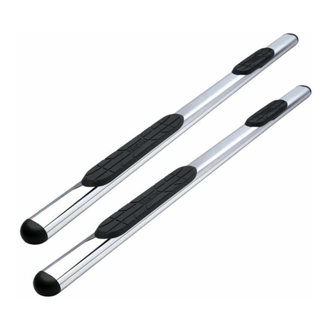
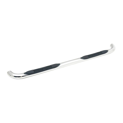
4” OVAL PLATINUM STEP BARS
2002-2008 DODGE RAM REGULAR CAB
P/N: 21-2320 /21-2325
ITEM QUANTITY CONTENTS TOOLS
1,2 1 SIDE BAR DRIVER & PASSENGER SIDE) 3/4” SOCKET
3 2 FRONT MOUNTING BRACKETS 3/4” WRENCH
4 2 REAR MOUNTING BRACKETS 9/16” SOCKET
5 2 FRONT SUPPORT STRAP 02-05 MODELS) 9/16” WRENCH
6 2 FRONT SUPPORT STRAP 2006-2008 MODELS) 18MM SOCKET
7 2 REAR SUPPORT STRAP 19MM SOCKET
8 4 BOLT PLATES RATCHET
9 4 BODY MOUNT SPACERS
11 4 M12 X 120MM HEX HEAD BOLT
12 4 1/2” X 2” HEX HEAD BOLT
13 2 1/2” X 1-1/2” HEX HEAD BOLT
14 12 1/2” FLAT WASHER
15 10 1/2” LOCK WASHER
16 2 1/2” HEX NUT
17 4 3/8” X 1-1/2” HEX HEAD BOLTS
18 12 3/8” FLAT WASHER
19 8 3/8” LOCK WASHER
20 8 3/8” HEX NUT
ARTICULO CANTIDAD CONTENIDO INSTRUMENTOS
1,2 1 TOME PARTIDO la BARRA CONDUCTOR & el LADO de PASAJERO) ENCHUFE 3/4”
3 2 FRENTE CRECIENTE PONE ENTRE PARENTESIS LLAVE INGLESA 3/4”
4 2 CRIE CORCHETES CRECIENTES ENCHUFE 9/16”
5 2 La CORREA DELANTERA del APOYO 02-05 MODELOS) LLAVE INGLESA 9/16”
6 2 La CORREA DELANTERA del APOYO 2006-2008 MODELOS) ENCHUFE 18MM
7 2 CORREA TRASERA de APOYO ENCHUFE 19MM
8 4 El CERROJO CHAPA TRINQUETE
9 4 ESPACIADORES de MONTE de CUERPO
11 4 CERROJO de CABEZA de MAL DE OJO M 12 x 120 MM
12 4 CERROJO de CABEZA de MAL DE OJO 1/2” X 2”
13 2 CERROJO de CABEZA de MAL DE OJO 1/2” X 1-1/2”
14 12 ARANDELA PLANA 1/2”
15 10 ARANDELA de CERRADURA 1/2”
16 2 TUERCA de MAL DE OJO 1/2”
17 4 CABEZA del MAL DE OJO CIERRA 3/8” 1-1/2”
18 12 ARANDELA PLANA 3/8”
19 8 ARANDELA de CERRADURA 3/8”
20 8 TUERCA de MAL DE OJO 3/8”
ARTICLE QUANTITE CONTENUS OUTILS
1,2 1 LA BARRE LATERALE LE CONDUCTEUR & LE COTE DE PASSAGER) 3/4” DOUILLE
3 2 MONTER DE DEVANT MET ENTRE PARENTHESES 3/4” CLE PLATE
4 2 MONTER D'ARRIERE MET ENTRE PARENTHESES 9/16” DOUILLE
5 2 LE SOUTIEN DE DEVANT SANGLE 02-05 MODELES) 9/16” CLE PLATE
6 2 LE SOUTIEN DE DEVANT SANGLE 2006-2008 MODELES) 18 MM LA DOUILLE
7 2 LE SOUTIEN POSTERIEUR SANGLE 19 MM LA DOUILLE
8 4 LE BOULON PLAQUE ENCLIQUETAGE A DENTS
9 4 SPACERS DE MONT DE CORPS
11 4 M12 X 120 MM LE BOULON DE TETE DE SORT
12 4 1/2” X 2” BOULON DE TETE DE SORT
13 2 1/2” X 1-1/2” BOULON DE TETE DE SORT
14 12 1/2” RONDELLE PLATE
15 10 1/2” RONDELLE FREIN
16 2 1/2” NOIX DE SORT
17 4 3/8” X 1-1/2” TETE DE SORT VERROUILLE
18 12 3/8” RONDELLE PLATE
19 8 3/8” RONDELLE FREIN
20 8 3/8” NOIX DE SORT
Page 1 of 3
INSTRUCTIONS-INSTRUCCIONES-CONSIGNES
4” OVAL PLATINUM STEP BARS
2002-2008 DODGE RAM REGULAR CAB
P/N: 21-2320 /21-2325
1. Verify all hardware contents listed above are present. Carefully read all instructions before installing.
2. Remove the body mount bolts from the driver side front cab mount. FIGURE 1)
3. Place one front mounting bracket on the underside of the mount, place mount spacer above mounting bracket on crew cab models.
4. Use the supplied M12 bolt, lock washer, and flat washer to secure the bracket; hand tighten at this time. FIGURE 2)
5. Repeat steps 2-4 for the rear mount.
6. Using the supplied bolt plate, 3/8” lock washer, 3/8” flat washer, and 3/8” hex nut; attach the front support strap to the factory slots located under the
rocker panel facing the frame. FIGURE 3,4)
7. With the supplied 3/8” hex bolt, lock washers, flat washers, and hex nuts; attach the other end of the support strap to the mounting bracket. Hand tighten at
this time. FIGURE 5)
8. Repeat steps 6-8 for the rear support strap.
9. Attach the driver side step bar to the mounting brackets using the supplied 1/2” hex bolts, lock washers, and flat washers. Hand tighten at this time.
10. Align the step bar in the position desired and tighten all hardware. FIGURE 6)
11. Repeat all steps for passenger side.
It is recommended to occasionally re-check and tighten all hardware.)
CARE INSTRUCTIONS
• REGULAR WAXING IS RECOMMENDED. DO NOT USE ANY TYPE OF POLISH OR WAX THAT MAY CONTAIN ABRASIVES
• STAINLESS STEEL PRODUCTS CAN BE CLEANED WITH MILD SOAP AND WATER. STAINLESS STEEL POLISH SHOULD BE USED TO POLISH SMALL
SCRATCHES.
• GLOSS BLACK FINISHES SHOULD BE CLEANED WITH MILD SOAP AND WATER
1. Verifique todo contenido de ferreteria listó encima de son presente. Lea con cuidado todas instrucciones antes de instalar.
2. Quite los cerrojos del monte del cuerpo del lado de conductor el monte delantero de la cabina. FIGURA 1)
3. Coloque una frente que monta corchete en la cara inferior del monte, coloca espaciador de monte encima de montar corchete en modelos de cabina de
tripulación.
4. Utilice el cerrojo M12 suministrado, arandela de cerradura, y arandela plana para asegurar el corchete; mano aprieta en este momento. FIGURA 2)
5. Repita los pasos 2-4 para el monte trasero.
6. Utilizando el plato suministrado de cerrojo, 3/8” arandela de la cerradura, 3/8” arandela plana, y 3/8” tuerca del mal de ojo; conecte la correa delantera de
apoyo a las ranuras de la fábrica situaron bajo el panel de balancín frente al marco. FIGURA 3.4)
7. Con el suministró 3/8” cerrojo del mal de ojo, arandelas de cerradura, arandelas planas, y tuercas de mal de ojo; conecte el otro fin de la correa de apoyo al
corchete creciente. La mano aprieta en este momento. FIGURA 5)
8. Repita los pasos 6-8 para la correa trasera de apoyo.
9. Conecte la barra del paso del lado de conductor a los corchetes crecientes que utilizan el suministró 1/2” cerrojos del mal de ojo, arandelas de cerradura, y
arandelas planas. La mano aprieta en este momento.
10. Alinee la barra del paso en la posición deseada y apriete todo ferreteria. FIGURA 6)
11. Repita todos pasos para el lado de pasajero.
Es recomendado para reexaminar ocasionalmente y para apretar todo ferreteria).
CUIDE las INSTRUCCIONES
• REGULAR DANDO CERA ES RECOMENDADO. No UTILICE NINGUN TIPO DE polaco ni la CERA QUE mayo CONTIENE ABRASIVO.
• Los PRODUCTOS del ACERO INOXIDABLE PUEDEN SER LIMPIADOS CON JABON Y AGUA TEMPLADOS. El ACERO INOXIDABLE polaco DEBE SER UTILIZADO
A PEQUEÑOS RASGUÑOS polacos.
• LUSTRE los FINES NEGROS DEBEN SER LIMPIADOS CON JABON Y AGUA TEMPLADOS
1. Sortez le produit de son emballage et vérifiez qu'il n'est pas endommagé. Vérifiez qu'il ne manque aucune pièce. Avant de commencer le montage, lisez
attentivement toutes les instructions en veillant à les comprendre correctement
2. Retirez les boulons de fixation de carrosserie de la fixation de cabine avant du côté conducteur. FIGURE 1)
3. Placez un support de montage avant sous la fixation. Pour les modèles équipés de double cabine, placez une entretoise de fixation au-dessus du support de
montage.
4. À l'aide des rondelles plates, des rondelles freins et d'un boulon M12, fixez le support. Serrez les attaches à la main pour le moment. FIGURE 2)
5. Répétez les étapes 2 à 4 pour la fixation arrière.
6. À l'aide d'un écrou hexagonal de 3/8 po 9,5 mm), d'une rondelle plate de 3/8 po 9,5 mm), d'une rondelle frein de 3/8 po 9,5 mm) et de la plaque pour
boulon fournis, fixez la patte de fixation avant aux fentes standard situées sous le bas de caisse face au cadre. FIGURE 3 et 4)
7. À l'aide des écrous hexagonaux, des rondelles plates, des rondelles freins et du boulon hexagonal de 3/8 po 9,5 mm), fixez l'autre extrémité de la patte de
fixation au support de montage. Serrez-les à la main pour le moment FIGURE 5)
8. Répétez les étapes 6 à 8 pour la patte de fixation arrière.
9. À l'aide des rondelles plates, des rondelles freins et des boulons hexagonaux de 1/2 po 1,2 cm), fixez le marchepied du côté conducteur aux supports de
montage. Serrez-les à la main pour le moment
10. Alignez le marchepied dans la position souhaitée et serrez toutes les attaches. FIGURE 6)
11. Répétez toutes les étapes pour le marchepied du côté passager.
Nous vous recommandons de vérifier et de resserrer régulièrement les attaches.)
ENTRETIEN ET INSTRUCTIONS
• CIREZ RÉGULIÈREMENT. N'UTILISEZ PAS DE PRODUITS DE POLISSAGE OU DE CIRAGE ABRASIFS
• NETTOYEZ LES PRODUITS EN ACIER INOXYDABLE AVEC DU SAVON DOUX ET DE L'EAU. UTILISEZ DES PRODUITS DE POLISSAGE POUR ACIER INOXYDA-
BLE AFIN DE POLIR LES PETITES ÉRAFLURES
• NETTOYEZ LES FINITIONS NOIRES VERNIES AVEC DU SAVON DOUX ET DE L'EAU.
Page 2 of 3
INSTRUCTIONS-INSTRUCCIONES-CONSIGNES
4” OVAL PLATINUM STEP BARS
2002-2008 DODGE RAM REGULAR CAB
P/N: 21-2320 /21-2325
FIGURE 1 FIGURE 2
FIGURE 4
FIGURE 5 FIGURE 6
FIGURE 3
Page 3 of 3

This manual suits for next models

1

Other Westin Automobile Accessories manuals

Westin 32-0240 User manual

Westin

Westin 32-0240 User manual

Westin 22-1065 User manual

Westin

Westin 22-1065 User manual

Westin 58-81085 User manual

Westin

Westin 58-81085 User manual

Westin HDX DROP STEP WTW User manual

Westin

Westin HDX DROP STEP WTW User manual

Westin 57-9003 User manual

Westin

Westin 57-9003 User manual

Westin 21-2900 User manual

Westin

Westin 21-2900 User manual

Westin 46-20055 User manual

Westin

Westin 46-20055 User manual

Westin 65-1535 User manual

Westin

Westin 65-1535 User manual

Westin 25-3360 User manual

Westin

Westin 25-3360 User manual

Westin PRO TRAXX 4 Series User manual

Westin

Westin PRO TRAXX 4 Series User manual

Westin 27-1855 User manual

Westin

Westin 27-1855 User manual

Westin 21-23290 User manual

Westin

Westin 21-23290 User manual

Westin 58-54165 User manual

Westin

Westin 58-54165 User manual

Westin 58-41215 User manual

Westin

Westin 58-41215 User manual

Westin 25-3440 User manual

Westin

Westin 25-3440 User manual

Westin 23-0925 User manual

Westin

Westin 23-0925 User manual

Westin 58-54085 User manual

Westin

Westin 58-54085 User manual

Westin 25-2310 User manual

Westin

Westin 25-2310 User manual

Westin 32-0055 User manual

Westin

Westin 32-0055 User manual

Westin 57-6005 User manual

Westin

Westin 57-6005 User manual

Westin Sportsman 40-0245 User manual

Westin

Westin Sportsman 40-0245 User manual

Westin 32-1660 User manual

Westin

Westin 32-1660 User manual

Westin 58-41075 User manual

Westin

Westin 58-41075 User manual

Westin 33-0880 User manual

Westin

Westin 33-0880 User manual

Popular Automobile Accessories manuals by other brands

Magneti Marelli AC161 Installation instruction

Magneti Marelli

Magneti Marelli AC161 Installation instruction

FDI uEZ GUI Start here

FDI

FDI uEZ GUI Start here

JCROffroad JT Install instructions

JCROffroad

JCROffroad JT Install instructions

Rostra VOXXElectronics 250-1930 owner's guide

Rostra

Rostra VOXXElectronics 250-1930 owner's guide

TOP VEHICLE TECH GR3FORD5 installation manual

TOP VEHICLE TECH

TOP VEHICLE TECH GR3FORD5 installation manual

Safe Fleet PRIME DESIGN AR-2000-BLK manual

Safe Fleet

Safe Fleet PRIME DESIGN AR-2000-BLK manual

Skoda Fabia Combi 5J Fitting instructions

Skoda

Skoda Fabia Combi 5J Fitting instructions

Camcar 40077 Al Mounting instructions

Camcar

Camcar 40077 Al Mounting instructions

Camcar 40089 AL Mounting instructions

Camcar

Camcar 40089 AL Mounting instructions

Impac Tradesman 2000 installation manual

Impac

Impac Tradesman 2000 installation manual

DVB OFFROAD BRSB-01 installation manual

DVB

DVB OFFROAD BRSB-01 installation manual

Safari Snorkel SS385HF installation guide

Safari Snorkel

Safari Snorkel SS385HF installation guide

ULTIMATE SPEED 279746 Assembly and Safety Advice

ULTIMATE SPEED

ULTIMATE SPEED 279746 Assembly and Safety Advice

SSV Works DF-F65 manual

SSV Works

SSV Works DF-F65 manual

ULTIMATE SPEED CARBON Assembly and Safety Advice

ULTIMATE SPEED

ULTIMATE SPEED CARBON Assembly and Safety Advice

Witter F174 Fitting instructions

Witter

Witter F174 Fitting instructions

WeatherTech No-Drill installation instructions

WeatherTech

WeatherTech No-Drill installation instructions

TAUBENREUTHER 1-336050 Installation instruction

TAUBENREUTHER

TAUBENREUTHER 1-336050 Installation instruction

manuals.online logo
manuals.online logoBrands
  • About & Mission
  • Contact us
  • Privacy Policy
  • Terms and Conditions

Copyright 2025 Manuals.Online. All Rights Reserved.