widos 6100 User manual

WIDOS Einsteinstraße 5 Phone +49 7152 9939 0
Wilhelm Dommer Söhne D-71254 Ditzingen Fax +49 7152 9939 40
Working Instructions
Translation
Heating element butt welding machine
WIDOS 6100
Keep for further use!

Product Identification
26.06.19 Working Instructions WIDOS 6100 Page 2 of 42
Model: Heating element butt welding machine
Type: WIDOS 6100
Serial number, year of construction: see type lable
Customer Entries
Inventory-No.:
Place of working:
Order of spare parts and after sales service:
Address of manufacturer WIDOS
Wilhelm Dommer Söhne GmbH
Einsteinstrasse 5
D-71254 Ditzingen
Phone: ++49 7152 9939 0
Fax: ++49 7152 9939 40
http://www.widos.de

Introduction
26.06.19 Working Instructions WIDOS 6100 Page 3 of 42
Purpose of the document
These working instructions give you information about all important questions which refer to the
construction and the safe working of your machine.
Just as we are, you are obliged to engage in these working instructions, as well.
Not only to run your machine economically but also to avoid damages and injuries.
Should questions arise, contact our service team in the factory or in our subsidiary companies.
We will help you with pleasure.
According to our interest to continuously improve our products and working instructions, we kindly ask
you to inform us about problems and defects which occur in exercise.
Thank you.
Structure of the working instructions
This manual is arranged in chapters, which belong to the different using phases of the machine.
Due to this structure, the searched information can be easily found.
26.06.2019 WIDOS
Wilhelm Dommer Söhne GmbH
Einsteinstraße 5
D-71254 Ditzingen
All rights reserved.
Reprinting only allowed with permission of the corporation.
Any changes prior to technical innovations.

Contents
26.06.19 Working Instructions WIDOS 6100 Page 4 of 42
1.DESCRIPTION OF THE PRODUCT ................................................................................ 6
1.1.Usage and purpose-oriented use........................................................................................6
1.2.Safety measures....................................................................................................................6
1.3.Conformity.............................................................................................................................6
1.4.Designation of the product ..................................................................................................6
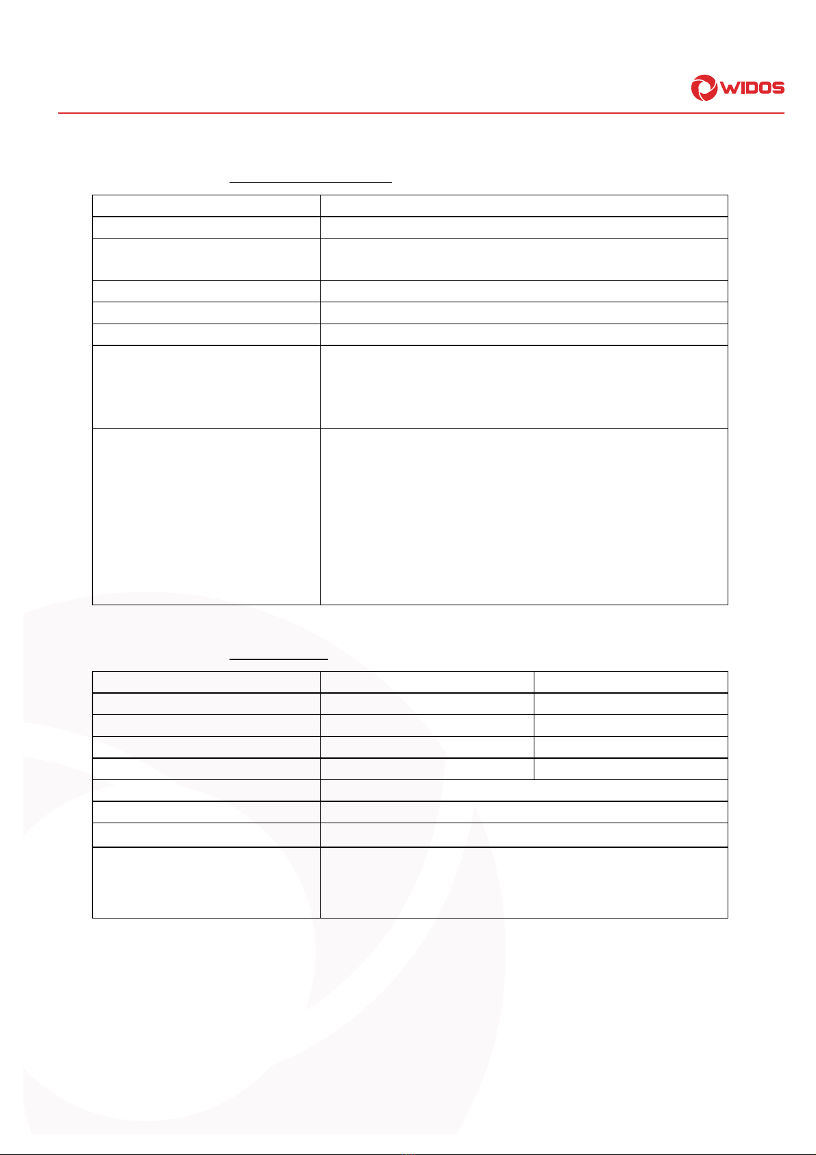
1.4.1.Technical data ......................................................................................................................7
1.4.1.1.WIDOS 6100 General data ............................................................................................7
1.4.1.2.Heating element............................................................................................................7
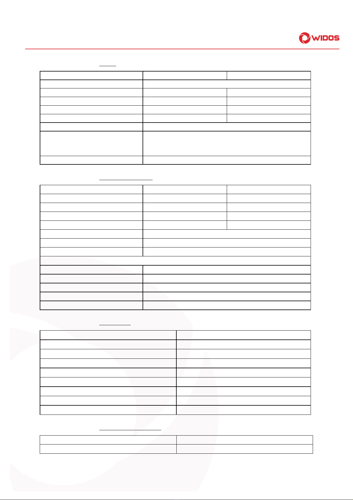
1.4.1.3.Planer..........................................................................................................................8
1.4.1.4.Hydraulic aggregate......................................................................................................8
1.4.1.5.Basic frame..................................................................................................................8
1.4.1.6.Lift-off device (optional).................................................................................................8
1.5.Machine overview .................................................................................................................9
1.6.Accessories:..........................................................................................................................9
2.SAFETY RULES ............................................................................................................ 10
2.1.Explanation of the symbols and indications ........................................................................... 10
2.2.Obligations of the owner................................................................................................... 11
2.3.Obligations of the worker.................................................................................................. 11
2.4.Measures of organisation ................................................................................................. 11
2.5.Information about safety precautions.............................................................................. 11
2.6.Instructions for the staff.................................................................................................... 11
2.7.Dangers while handling the machine .............................................................................. 12
2.8.Maintenance, inspection and repair................................................................................. 12
2.9.Dangers caused by electric energy.................................................................................. 12
2.10.Dangers caused by the hydraulics................................................................................... 12
2.11.Specific dangers ................................................................................................................ 13
2.11.1.Danger of catching clothes by the planer.............................................................................. 13
2.11.2.Danger of being burnt by heating element, reception box and welding area ............................. 13
2.11.3.Danger of stumbling over electric / hydraulic wires ............................................................... 13
2.11.4.Danger of squeezing by clamping devices and guideways...................................................... 13
2.11.5.Risk of injury by noises ........................................................................................................ 14
2.12.Structural modifications on the machine........................................................................ 14
2.13.Cleaning the machine........................................................................................................ 14
2.14.Warranty and liability......................................................................................................... 14
3.FUNCTIONAL DESCRIPTION ....................................................................................... 15
4.OPERATING AND INDICATING ELEMENTS ............................................................... 16
4.1.Elements on the aggregate............................................................................................... 16
4.2.Elements at planer and heating element......................................................................... 17
4.3.Separating device for heating element............................................................................ 17

Contents
26.06.19 Working Instructions WIDOS 6100 Page 5 of 42
5.STARTING AND OPERATING ...................................................................................... 18
5.1.Safety indications .............................................................................................................. 18
5.2.Connection of hydraulic aggregate with basic machine ............................................... 19
5.3.Replacing the reduction inserts ....................................................................................... 19
5.4.Setting the heating element temperature........................................................................ 20
5.5.Welding process ................................................................................................................ 20
5.6.Lift-off device (optional) .................................................................................................... 22
5.6.1.Mounting of the machine..................................................................................................... 22
5.6.2.Mounting the lift-off device.................................................................................................. 22
5.6.3.Transport........................................................................................................................... 22
6.WELDING LOG AND TABLES ...................................................................................... 23
7.MAINTENANCE AND REPAIR ...................................................................................... 25
7.1.Maintenance and inspection, repair ...................................................................................... 25
7.2.Clamping elements ................................................................................................................ 25
7.3.Planer .................................................................................................................................. 25
7.4.Storage................................................................................................................................ 25
7.5.Used hydraulic oil .............................................................................................................. 25
7.6.Checking the hydraulic oil level ....................................................................................... 26
7.7.Venting the hydraulic cylinders........................................................................................ 26
7.8.Disposal .............................................................................................................................. 27
8.TRANSPORT ................................................................................................................. 28
9.HYDRAULIC AND ELECTRIC DIAGRAMS .................................................................. 29
9.1.Electric diagram 400 V....................................................................................................... 30
9.2.Electric diagram 230 V....................................................................................................... 38
10.SPARE PARTS LIST ..................................................................................................... 41
11.DECLARATION OF CONFORMITY .............................................................................. 42

WIDOS Einsteinstraße 5 Phone +49 7152 9939 0
Wilhelm Dommer Söhne D-71254 Ditzingen Fax +49 7152 9939 40
26.06.19 Working Instructions WIDOS 6100 Page 6 of 42
1. Description of the product
This chapter gives important basic information about the product and its prescribed use.
All technical details of the machine are put together as a general arrangement.
1.1. Usage and purpose-oriented use
The WIDOS 6100 has been designed for heating element butt welding of pipes and fittings with a
diameter range of Ø = 315 - 630mm.
(standard diameters: 315 / 355 / 400 / 450 / 500 / 560 / 630mm)
It is a machine for construction sites and particularly designed for the usage on-site, as well as in the
workshop.
For this reason, the frame is kept small so that it can be used even under difficult conditions (e.g.
ditch).
All use going beyond is not purpose-oriented.
The manufacturer is not responsible for damages caused by misuse.
The risk is held only by the user.
Also part of the purpose oriented use is
respecting all the indications of the working instructions and
performing the inspection and maintenance works.
1.2. Safety measures
In case of wrong use, wrong operation or wrong maintenance, the machine itself or products standing
nearby can be damaged or destroyed.
Persons being in the endangered area may be injured.
Therefore these working instructions have to be thouroughly read and the corresponding safety
regulations must be necessarily adhered to.
1.3. Conformity
The machine corresponds in its construction to the valid recommendations of the European
Community as well as to the according European standard specifications.
The development, manufacturing and mounting of the machine were made very carefully.
1.4. Designation of the product
The product is designated by two type labels which are attached at the aggregate and at the basic
machine.
They contain the type, the serial number and the year of construction of the machine.

Description of product Chapter 1
26.06.19 Working Instructions WIDOS 6100 Page 7 of 42
1.4.1. Technical data
1.4.1.1. WIDOS 6100 General data
Material which can be welded: PP, PE80, PVDF, PE 100
Pipe diameter range: outside = 315 - 630 mm
Transport box: (lxwxh):
Weight:
approx. 1700 x 1560 x 1360 (mm)
approx. 150 kg
Weight (without accessories): 500 kg
Fuse: 16 A
Wire cross section: 1.5 mm²
Emissions -Noises exceeding 80 dB (A) may occur; during planing it is
obligatory to wear ear protection!
- When using the named pipe materials and when welding
below 260°C no toxicant damp arises
Ambient conditions in the welding
area
-take care for cleanness (no dust at the welding area)
-if secured by an appropriate measurement that allowed
conditions for welding are indicated, it is possible to work in
any outside temperature condition as far as the welder is not
constrained in its manual skill.
-avoid humidity, if necessary use a welding tent
-avoid strong sun rays influence
-protect from wind, shut the pipe ends
1.4.1.2. Heating element
400 V 230 V
Power: 5,9 kW 10,08 kW
Voltage: 400 V (+- 10%) 230 V (+- 10%)
Current: 26 A 25,2 A
Frequency: 50 Hz 50 Hz
Surface: nonstick-coated
Outside-: 684 mm
Weight: -appr. 32 kg
Attached elements: -Electronic temperature control
-Control lamps, on/off-switch
-Connecting cable with plug

Description of product Chapter 1
26.06.19 Working Instructions WIDOS 6100 Page 8 of 42
1.4.1.3. Planer
400 V 230 V
Motor: Three-phase alternating current motor
Power: 1,5 kW 5,75 kW
Voltage: 400 V (+- 10%) 230 V (+- 10%)
Nominal current 3,7 A 2,5 A
Frequency: 50 Hz (+- 10%) 50 Hz (+- 10%)
Speed of motor: appr. 140 rpm
Atached elements: -On/off switch
-Connecting cable with plug
-Locking device
Weight: appr. 100 kg
1.4.1.4. Hydraulic aggregate
400 V 230 V
Power: 0,56 kW 0,3 kW
Voltage: 400 V (+- 10%) 230 V (+- 10%)
Nominal current 4 A 2,7 A
Frequency: 50 Hz 50 Hz
Displacement of phase: appr. 18°
Hydraulic oil tank: appr. 1 L
Insulation system IP 54
Electromotor and pump:
Speed: 2720 rpm
Max. working pressure of pump: appr. 130 bar
Working pressure: 0-130 bar adjustable
Volume velocity: 3,5 L/min
Weight: appr. 30 kg
1.4.1.5. Basic frame
Reduction inserts, pipe supports: Optional dimensions
Material frame: Structural steel
Material reduction inserts: Aluminium
Max. force (F=P*A): 17.3 kN (at p= 100 bar)
Cylinder-: 60 mm
Piston rod-: 50 mm
Length of stroke of cylinder: 300 mm
Weight appr. 226 kg
Velocity of piston rod: 3,4 cm/s
1.4.1.6. Lift-off device (optional)
Lift capacity: appr. 100 kg
Weight (complete) appr. 32 kg
See spare parts list for order numbers and single parts

Description of product Chapter 1
26.06.19 Working Instructions WIDOS 6100 Page 9 of 42
1.5. Machine overview
1 Hydraulic aggregate
2 Heating element
3 Planer
4 Reception box
5 Basic machine with clamping devices
6 Lift-off device (optional)
1.6. Accessories:
Following tools and accessories are part of the delivery:
1 Tool bag for 10 parts
1 Socket spanner size 27
1 Torx screwdriver T10
1 each Allen key angulate, size 3 / 12
1 Allen key with T grip size 7
Optional Different reduction inserts,
roller stands for the pipes,
transformer 42V,
crane for insertion and removal of heating element and planer
1
5
2
3
4
6

WIDOS Einsteinstraße 5 Phone +49 7152 9939 0
Wilhelm Dommer Söhne D-71254 Ditzingen Fax +49 7152 9939 40
26.06.19 Working Instructions WIDOS 6100 Page 10 of 42
2. Safety rules
The base for the safe handling and the fault-free operation of this machine is the knowledge of the
basic safety indications and rules.
These working instructions contain the most important indications to run the machine
safely.
The safety indications are to be followed by all persons working on the machine.
2.1. Explanation of the symbols and indications
In the working instructions, following denominations and signs are used for dangers:
This symbol means a possibly danger for the life and the health of persons.
The disrespect of these indications may have heavy consequences for the health.
This symbol means a possible dangerous situation.
The disrespect of these indications may cause slight injuries or damages on goods.
This symbol means a possible dangerous situation by moving parts of the machine
The disrespect of these indications may cause heavy crushings of parts of the body
resp. damages of parts of the machine.
This symbol means a possible dangerous situation due to hot surfaces.
The disrespect of these indications may conduct to heavy burns, respectively to self-
ignition or even fire.
This symbol means a possible risk of injury by noises exceeding 80 dB(A).
Ear protection is obligatory
This symbol gives important indications for the proper use of the machine.
The disrespect of these indications may conduct to malfunctions and damages on the
machine or on goods in the surrounding.
Under this symbol you get user tips and particularly useful information.
It is a help for using all the functions on your machine in an optimal way and helps you
to make the job easier.
The regulations for the prevention of accidents are valid (UVV).

Safety Rules Chapter 2
26.06.19 Working Instructions WIDOS 6100 Page 11 of 42
2.2. Obligations of the owner
The owner is obliged only to let persons work at the machine, who
know about basic safety and accident prevention rules and are instructed in the handling of the
machine, as well as who
have read and understood the safety chapter of this manual and certify this by their signature.
The safety-conscious working of the staff has to be checked in regular intervals.
2.3. Obligations of the worker
All persons who are to work at the machine are obliged before working:
to follow the basic safety and accident protection rules.
to have read and understood the safety chapter and the warnings in this manual and to confirm by
their signature that they have well understood them.
to inform themselves about the functions of the machine before using it.
2.4. Measures of organisation
All equipment required for personal safety is to be provided by the owner.
All available safety equipment is to be inspected regularly.
2.5. Information about safety precautions
The working instructions have to be permanently kept at the place of use of the machine. They are
to be at the operator's disposal at any time and without effort.
In addition to the manual, the common valid and the local accident protection rules and regulations
for the environmental protection must be available and followed.
All safety and danger indications on the machine have to be in a clear readable condition.
Every time the machine changes hands or is being rent to third persons, the working instructions
are to be sent along with and their importance is to be emphasized.
2.6. Instructions for the staff
Only skilled and trained persons are allowed to work at the machine.
It must be clearly defined who is responsible for transport, mounting and dismounting, starting the
operation, setting and tooling, operation, maintenance and inspection, repair and dismounting.
A person who is being trained may only work at the machine under supervision of an experienced
person.

Safety Rules Chapter 2
26.06.19 Working Instructions WIDOS 6100 Page 12 of 42
2.7. Dangers while handling the machine
The machine WIDOS 6100 is constructed according to the latest technical standard and the
acknowledged technical safety rules. However, dangers for the operator or other persons standing
nearby may occur. Also material damages are possible.
The machine may only be used
according to the purpose-oriented usage
in safety technical impeccable status
Disturbances, which may affect the safety of the machine must be cleared immediately
2.8. Maintenance, inspection and repair
All maintenance and repair works have to be basically performed with the machine in off
position.
During this the machine has to be secured against unauthorized switching on.
Prescribed maintenance and inspection works should be performed in time. The DVS
gives the advice of inspection works after 1 year.
For machines with a specially high usage percentage the testing cycle should
be shortened .
The works should be performed at the WIDOS GmbH company or by an
authorized partner.
2.9. Dangers caused by electric energy
Only skilled persons are allowed to work at electrical appliances!
The electrical equipment of the machine has to be checked regularly. Loose
connections and damaged cables have to be replaced immediately.
If works at alive parts are necessary, a second person has to assist who can disconnect the
machine from the mains if necessary.
All electric tools (heating element, planer and aggregate) have to be protected from rain and
dropping water (if need be use a welding tent).
According to VDE 0100, the use on construction sites is only allowed with a power distributor with a
FI-safety switch.
2.10. Dangers caused by the hydraulics
System parts and pressure hoses should be made pressureless before beginning of any
repair works. Even if the machine is switched off, pressure may be in the hydraulic
accumulator!
There is a danger of injuring the eyes by hydraulic oil squirting out.
Damaged hydraulic hoses have to be immediately replaced.
Make a visual inspection of the hydraulic hoses before each work beginning.
The hydraulic oil is inedible !

Safety Rules Chapter 2
26.06.19 Working Instructions WIDOS 6100 Page 13 of 42
2.11. Specific dangers
2.11.1. Danger of catching clothes by the planer
You can cut yourself or even get bones broken!
Only wear clothes tight to the body.
Do not wear rings or jewellery during the work.
If necessary, wear a hair-net.
Always put the planer back into the reception box after and before each use.
Transport the planer at the handle only. Do not touch the surfaces.
Switch the planer on only for usage.
If the planing pressure is too high, there is the danger that the planer tilts during planing. For that
reason do not press the pipe ends stronger than necessary against the planer. If necessary, hold
the planer firmly.
2.11.2. Danger of being burnt by heating element, reception box and welding
area
You can burn yourself, inflammable materials can be ignited.
The heating element temperature is heated up to more than 250°C !
Do not touch the surfaces of the heating element.
Do not leave the heating element unsupervised.
Take enough safety distance to inflammable materials.
Do wear safety gloves.
Always put the heating element back into the reception box after and before each use.
Transport the heating element at the handle only.
2.11.3. Danger of stumbling over electric / hydraulic wires
Make sure that no person has to step over the wires.
Lay the wires in such a way that the danger is kept to a minimum.
2.11.4. Danger of squeezing by clamping devices and guideways
There is a danger of serious injuries: on the one hand between the inner clamping
devices and on the other hand between the outer clamping device and the end of the
guideway.
Do not stand or put hands between clamped pipe ends.
Do not stand or put hands between the inner clamping tools with not yet clamped pipes.
Do not block opening and closing of the machine slides.

Safety Rules Chapter 2
26.06.19 Working Instructions WIDOS 6100 Page 14 of 42
2.11.5. Risk of injury by noises
Noises exceeding 80 dB (A) may occur; during planing it is obligatory to wear ear
protection!
2.12. Structural modifications on the machine
No modifications, extensions or reconstructions may be made on the machine without permission
of the manufacturer.
Machine parts which are not in a perfect condition are to be replaced immediately.
Only use original WIDOS spare and wear parts.
In case of purchase orders please always state the machine number!
2.13. Cleaning the machine
The used materials and tissues are to be handled and disposed of properly, especially:
when cleaning with solvents
when lubricating with oil and grease
2.14. Warranty and liability
Fundamentally our "General Sales and Delivery Conditions" are valid.
They are at the owner's disposal latest when signing the contract.
Guarantee and liability demands referring to personal injuries or damages on objects are excluded if
they are caused by one or several of the following reasons:
not using the machine according to the prescriptions
inexpert transport, mounting, starting, operating, and maintenance of the machine
running the machine with defective or not orderly mounted safety appliances
ignoring the information given in this manual
structural modifications on the machine without permission
unsatisfactory checking of parts of the machine, which are worn out
repairs performed in an inexpert way
In case of catastrophes and force majeure

WIDOS Einsteinstraße 5 Phone +49 7152 9939 0
Wilhelm Dommer Söhne D-71254 Ditzingen Fax +49 7152 9939 40
26.06.19 Working Instructions WIDOS 6100 page 15 of 42
3. Functional description
Basically, the international and national process guidelines are to be followed !
The plastic pipes are clamped in the clamping devices. Then the front sides of the pipes are cut plane
and parallel by means of the planer and the misalignment of the pipes is checked.
The cleaned and heated heating element is inserted and the pipes are pressed against the heating
element under defined adjusting pressure. This process is called "adjusting".
After the prescribed bead height being reached, pressure is reduced, the heating time begins. The
function of this time is to heat up the pipe ends.
After expiration of the heating time, the slides are opened, the heating element is removed quickly and
the pipes are driven together again. The time gap from the removal of the heating element to joining
the pipes is called change over time.
The pipes are joined under prescribed welding pressure and then cool down under pressure (cooling
time).
The welded joint can be unclamped, the welding process is finished.
Heating element heats
the pipes up to welding
temperature
Finished welding with
internal and external
bead

WIDOS Einsteinstraße 5 Phone +49 7152 9939 0
Wilhelm Dommer Söhne D-71254 Ditzingen Fax +49 7152 9939 40
26.06.19 Working Instructions WIDOS 6100 Page 16 of 42
4. Operating and indicating elements
4.1. Elements on the aggregate
No. Name Function
7 Pressure gauge Digital display of the hydraulic pressure
8 Valve lever Opening the slides. There are 4 different positions:
- to the left side: slides close.
- in the middle (usual position): the pressure which is
currently achieved is kept (also by means of the
built-in hydraulic accumulator)
- slightly to the right side (position pressureless):
a possibly existing pressure is released without
moving the slides. Due to the hydraulic accumulator,
it takes about 10 s until the pressure is completely
released.
- to the right side: slides open
9 Setting screw for pressure
relief valve
- Limitation of the pressure to the desired value.
10 Hydraulic connection for
closing the slides
- Non-dropping quick-acting coupling
11 Hydraulic connection for
opening the slides
- Non-dropping quick-acting coupling
12 Screw with oil dipstick - checking the oil level
- oil filler neck
Planer and heating element have to be connected to a power distributor for building sites (400 Volt).
7
8
10
11
9
12
Mains cable
230V / 50HZ
Power supply
for hydraulic
agg
r
egate
Label „opening/
closing“
Indicating label
Setting the
pressure relief
valve

Operating and Indicating Elements Chapter 4
26.06.19 Working Instructions WIDOS 6100 Page 17 of 42
4.2. Elements at planer and heating element
No. Name Function
13 On/off switch for planer - For switching on/off the planer.
- Switch off the planer after use.
14 Lever - For holding the planer when lifting/removing.
- Lever can be screwed off.
15 Eye and eye with locking bolt - locking the planer/ heating element- For holding the planer
when lifting/removing.
- Lever can be screwed off. in basic machine, (In order to remove
the planer, pull locking bolt into arrow direction.
16 Lifting screw - For lifting / inserting the heating element / planer with the
lift-off device.
17 Display of temperature -Digital display of set heating element temperature. Three
different displays are possible.
For meaning of the displays please refer to point 5.4
Setting the heating element temperature
18 Thermostat - For setting the required temperature.
19 Grip - For holding the heating element when lifting / removing.
4.3. Separating device for heating element
There is a tear-off bar mounted between the
movable and the fixed clamping shells on the basic
machine. It prevents the heating element from
sticking to the heated-up pipe ends.
When inserting the heating element take care that
it lies in the zone of the throat of the tear-off bar
(see arrow).
13
16
14
17 18
19
15

WIDOS Einsteinstraße 5 Phone +49 7152 9939 0
Wilhelm Dommer Söhne D-71254 Ditzingen Fax +49 7152 9939 40
26.06.19 Working Instructions WIDOS 6100 Page 18 of 42
5. Starting and operating
The instructions of this chapter are supposed to initiate in the operation of the machine and lead
during the appropriate starting of the machine.
This includes:
- the safe operation of the machine
- using all the possible options of the machine
- economic operation of the machine
5.1. Safety indications
The machine may only be operated by initiated and authorized persons.
For the qualification, a plastic welding exam can be taken according to DVS and DVGW.
In situations of danger for persons and the machine, the mains plug has to be unplugged
immediately.
In case of power failure, there may still be pressure in the hydraulic system.
Therefore release pressure if need be.
After completion of the welding work and during breaks the machine has to be switched
off. Further take care that no unauthorized person has access.
Protect the machine from wetness and humidity !
According to VDE 0100, the use on construction sites is only allowed with a power
distributor with a FI-security protective switch.
Check the oil level of the hydraulic system before each starting of the control unit in
order to avoid damages on the pump. The oil level must be between the two marks at the
oil dipstick.
If necessary, add hydraulic oil of the quality HLPD 32.
The heating element surfaces must be clean, especially non greasy, therefore they need
to be cleaned shortly before each welding or in case of dirtiness by means of a fibre-
free paper and a cleaning agent (e.g. PE cleaner or pipe cleaning tissues which are
available at the WIDOS company).
The anti-adhesive coating of the heating element must remain undamaged in the working
area.
Take care that all hydraulic and electric connections are connected.
Make sure that pump and planer are connected in a way that they turn in right-hand
direction.
Take into account the surrounding conditions:
-The welding may not be performed under direct sun rays influence.
-Use a welding umbrella if necessary.
If the surrounding temperature is under 5°C, measures have to be taken:
-Use a welding tent or preheat the pipe ends if necessary.
In addition, take measures against rain, wind and dust.

Starting and Operating Chapter 5
26.06.19 Working Instructions WIDOS 6100 Page 19 of 42
5.2. Connection of hydraulic aggregate with basic machine
Connect the aggregate to the mains supply (230 V/50 Hz).
Connect planer and heating element to a power distributor for building sites with 400 V (right rotary
field).
Put the hydraulic hoses of the basic machine into the quick-acting couplings of the hydraulic
aggregate.
Lay the hydraulic and electric wires carefully (danger of stumbling)
5.3. Replacing the reduction inserts
Unscrew the mounted reduction inserts by means of the provided Allan key.
Screw the reduction inserts with the corresponding diameter into the clamping devices. Pipes with
OD 630 have to be clamped in the basic clamping devices.
If necessary (e.g. for T-pieces) the outer fixed clamping device can be dismantled by unscrewing
the three hexagon socket screws.
Dismantling of the outer fixed clamping device

Starting and Operating Chapter 5
26.06.19 Working Instructions WIDOS 6100 Page 20 of 42
5.4. Setting the heating element temperature
As soon as the heating element is connected to the mains (400 V / 16A), it starts heating up to the
desired temperature. Set the temperature with a screw driver at the adjusting knob.
2.2.0
Display: DESIRED temperature + blinking points between the numbers.
The heating element is being heated up, the desired temperature is not yet
reached. This display disappears after short time, followed by three lines.
- - -
Display: Three lines.
The heating element is being heated up, the desired temperature is not yet
reached.
1 8 0
Display: ACTUAL temperature (without blinking points).
Appears as soon as a temperature of > 170 °C is reached and rises continuously
to DESIRED temperature. The desired temperature is maintained by a certain
pulse-position ratio.
5.5. Welding process
The respectively valid welding prescriptions (ISO / CEN / DVS...) are to be
basically followed.
There is the danger of serious bruising.
On the one hand between the inner clamping devices, on the other hand
between the outer clamping device and the end of the guide bar.
Do wear safety gloves as a protection against burning !
A stop-watch must be available for recording the actual times for heating and cooling.
A welding table must be available from which the parameters for the pipe dimensions to be welded
prescribed by the welding prescriptions may be taken.
Connect the heating element and set the heating element temperature (see chapter 5.4).
Screw in the reduction inserts according to the outside diameter of the pipes to be welded.
Lay the pipes to be welded into the clamping devices, tighten firmly the clamping nuts and align the
pipes with respect to each other. In case of long pipe ends, use WIDOS roller stands for that
purpose.
Terminal box with
control
Display
Temperature adjusting knob
Table of contents
Other widos Welding System manuals

widos
widos 4400 User manual

widos
widos 8000 WM SPA User manual

widos
widos HRG 14 User manual

widos
widos PSM 10 XHS User manual

widos
widos 4001 User manual

widos
widos SPA 600 User manual

widos
widos 2500 / OD 315 User manual

widos
widos 10000 mobile User manual

widos
widos PSM 20 User manual

widos
widos 4955 User manual

widos
widos WELD IT 315 Steel User manual

widos
widos 7511 User manual

widos
widos MAXIPLAST User manual

widos
widos 5500 CNC 3.0 User manual

widos
widos 7000 WM User manual

widos
widos 4002 S WI CNC User manual

widos
widos HRG 16, Segment User manual

widos
widos ASM 160 User manual

widos
widos 2500 / OD 250 User manual

widos
widos MINIPLAST 2 / T-Piece User manual