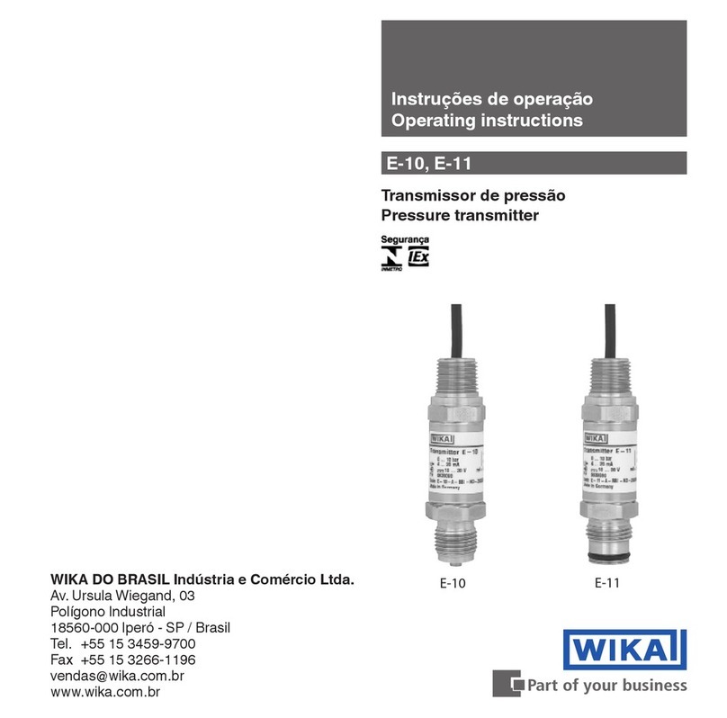
WIKA E-11 User manual

E-10, E-11
Pressure transmitter
Transmetteur de pression
WIKA Instrument, LP – U.S. Headquarters
1000 Wiegand Boulevard
Lawrenceville, GA 30043
Phone: (770) 513-8200
Fax: (770) 338-5118
info@wika.com
www.wika.us
WIKA Instruments Ltd.
3103 Parsons Rd.
Edmonton, AB T6N 1C8
Phone : (780) 463-7035
Fax : (780) 462-0017
info@wika.ca
www.wika.ca
Operating instructions
Mode d'emploi
2451730.11 01/2015 US/FR
E-10
Current terms and conditions apply.
Details are available on ...
www.wika.us
Les modalités et conditions en vigueur s'appliquent.
Vous trouverez plus de renseignements à l'adresse
suivante :
www.wika.ca
E-11

2451730.11 01/2015 US/FR
2WIKA operating instructions, models E-10, E-11
US
Contents Page
1. Important details for your information 2
2. A quick overview for you 3
3. Signs, symbols and abbreviations 3
4. Function 5
5. For your safety 6
6. Packaging 7
7. Starting, operation 8
8. Maintenance, accessories 14
9. Trouble shooting 15
10. Storage, disposal 17
11. Control Drawing 18
Sommaire Page
1. Détails importants pour votre information 19
2. Une brève vue générale pour vous 20
3. Signes, symboles et abréviations 20
4. Fonction 21
5. Pour votre sécurité 22
6. Emballage 23
7. Mise en marche, fonctionnement 24
8. Entretien, accessoires 30
9. Dépannage 31
10. Stockage, mise au rebut 33
11. Dessin de contrôle 34

2451730.11 01/2015 US/FR
3
US
WIKA operating instructions, models E-10, E-11
1. Important details for your information
Read these operating instructions before installing and starting the pressure transmitter. Keep
the operating instructions in a place that is accessible to all users at any time.
The following installation and operating instructions have been compiled by us with great care
but it is not feasible to take all possible applications into consideration.These installation and
operation instructions should meet the needs of most pressure measurement applications.
If questions remain regarding a specific application, you can obtain further information:
■
Via our Internet address www.wika.de / www.wika.com
■
The product data sheet is designated as APE E-10
■
Contact WIKA for additional technical support (770) 513 8200
If the serial number on the case and/or the 2D code on the hexagon gets illegible (e.g. by
me-chanical damage or repainting), the retraceability of the instrument is not possible any more.
WIKA pressure transmitters are carefully designed and manufactured using state-of-the-art
technology. Every component undergoes strict quality and environmental inspection before
assembly and each instrument is fully tested prior to shipment.
Intended use
Use the explosion proof pressure transmitter to transform the pressure into an electrical signal in
hazardous areas.
FM and CSA certification
Pressure transmitter for operation in hazardous areas in compliance with the respective certifi-
cate (see Control drawing No. 2323872, section 12).
FM and CSA Approval ratings:
Explosion proof: Class I, Division 1, Groups A, B, C and D
Dust-ignitionproof: Class II, Division 1, Groups E, F, and G; Class III, Division 1

2451730.11 01/2015 US/FR
4WIKA operating instructions, models E-10, E-11
US
1. Important details ... 3. Signs, symbols and abbreviations
Knowledge required
Install and start the pressure transmitter only if you are familiar with the relevant regulations and
directives of your country and if you have the qualification required.You have to be acquainted
with the rules and regulations on hazardous areas, measurement and control technology and
electric circuits, since this pressure transmitter is „electrical equipment“. Depending on the
operating conditions of your application you have to have the corresponding knowledge, e.g. of
aggressive media.
2. A quick overview for you
If you want to get a quick overview, read Chapters 3, 5, 7 and 10.There you will get some short
safety instructions and important information on your product and its starting. Read these
chapters in any case.
3. Signs, symbols and abbreviations
WARNING!
Potential danger to life or of severe injuries.
WARNING!
Instructions for hazardous areas: "Potential danger of explosion, to life or of severe
injuries!
Notice
Important information, malfunction.

2451730.11 01/2015 US/FR
5
US
WIKA operating instructions, models E-10, E-11
FM, Factory Mutual
The product was tested and certified by FM Approvals. It complies with the applicable
US-American standards on safety (including explosion protection).
CSA, Canadian Standard Association
The product was tested and certified by CSA International. It complies with the
applicable Canadian and US-American standards on safety (including explosion
protection).
2-wire Two connection lines are intended for the voltage supply.
The supply current is the measurement signal.
3-wire Two connection lines are intended for the voltage supply.
One connection line is intended for the measurement signal.
4. Function
E-10: Pressure connection (explosion proof) with internal diaphragm (standard version).
E-11: Pressure connection with flush diaphragm (explosion proof) for highly viscous or solids
entrained media which might clog the pressure port.
Function
The pressure prevailing within the application is transformed into a standardised electrical signal
through the deflection of the diaphragm, which acts on the sensor element with the power supply
fed to the transmitter.This electric signal changes in proportion to the pressure and can be evalu-
ated correspondingly
3. Signs, symbols and abbreviations / 4. Function

2451730.11 01/2015 US/FR
6WIKA operating instructions, models E-10, E-11
US
5. For your safety
5. For your safety
WARNING!
■
Select the appropriate pressure transmitter with regard to scale range, perfor-
mance and specific measurement conditions prior to installing and starting the
instrument.
■
Observe the relevant national regulations (e.g.: NEC, CEC) and observe the appli-
cable standards and directives for special applications (e.g. with dangerous media
such as acetylene, flammable gases or liquids and toxic gases or liquids and with
refrigeration plants or compressors). If you do not observe the appropriate regula-
tions, serious injuries and/or damage can occur.
■
Open pressure connections only after the system is without pressure.
■
Please make sure that the pressure transmitter is only used within the overload
threshold limit all the time.
■
Observe the ambient and working conditions outlined in section 7 „Technical
data”.
■
Ensure that the pressure transmitter is only operated in accordance with the provi-
sions i.e. as described in the following instructions.
■
Do not interfere with or change the pressure transmitter in any other way than
described in these operating instructions.
■
Remove the pressure transmitter from service and mark it to prevent it from being
used again accidentally, if it becomes damaged or unsafe for operation.
■
Take precautions with regard to remaining media in removed pressure transmitter.
Remaining media in the pressure port may be hazardous or toxic.
■
Have repairs performed by the manufacturer only.

2451730.11 01/2015 US/FR
7
US
WIKA operating instructions, models E-10, E-11
5. For your safety / 6. Packaging
WARNING!
Consider the respective country specific regulations for installation and operation in
hazardous areas (e.g.: NEC, CEC). If you do not observe these stipulations, serious
injuries and/or damage can occur.
6. Packaging
Has everything been supplied?
Check the scope of supply:
■
Completely assembled pressure transmitters; with flush version E-11 including pre-assem-
bled sealings and protection cap.
■
Inspect the pressure transmitter for possible damage during transportation. Should there be
any obvious damage, inform the transport company and WIKA without delay.
■
Keep the packaging, as it offers optimal protection during transportation (e.g. changing instal-
lation location, shipment for repair).
■
Ensure that the pressure connection thread and the connection contacts will not be damaged.
In order to protect the diaphragm, the pressure connection of the instrument E-11 is provided
with a special protection cap.
■
Remove this protection cap only just before installing the pressure transmitter in order to
prevent any damage to the diaphragm or the thread.
■
Keep the protection cap of the pressure connection thread and the diaphragm for later
storage or transport.
■
Mount the protection cap when removing and transporting the instrument.

2451730.11 01/2015 US/FR
8WIKA operating instructions, models E-10, E-11
US
Use to install the transmit-
ter process connection
max. 50 Nm / 442 lbf
Use only to secure
transmitter while installing
electrical conduit
Transmitter E-10
0 ... 10 bar
4 ... 20 mA
10 ... 30 V
P# 0639080
Code E-10-XXXXXXX
brown+ green-
brown S+ green GND
WIKA Alexander Wiegand SE & Co. KG 63911 Klingenberg Made in Germany
3D
Type 4
Explosionproof for
CLI, DIV.1, GRP A,B,C,D
CLII, DIV.1, GRP E, F, G; CL III
Ta < 60 °C, T6, Ta < 105 °C, T4
factory sealed,
conduit seal not required
CSA Single Seal ANSI/ISA12.27.01
-30 °C < Tprocess < 100 °C
7. Starting, operation
Product label (example)
Pressure range
Signal
Power Supply
P #: Product No.
PIN assignment
Coded
manufacture
date
Make sure the ventilation
port remains open to
atmospharic pressure.
7. Starting, operation
Required tools
Wrench (flats 27 or flats 41), screw driver
Diaphragm test for your safety
It is necessary that before starting the pressure transmitter you test the diaphragm visually, as
this is a safety-relevant component.
WARNING!
■
Pay attention to any liquid leaking out, for this points to a diaphragm damage.
■
Check the diaphragm visually for any damage (E-11).
■
Use the pressure transmitter only if the diaphragm is undamaged.
■
Use the pressure transmitter only if it is in a faultless condition as far as the
safety-relevant features are concerned.
Mechanical connection
If there is no serial number on the product label, the number on the hexagon will apply.

2451730.11 01/2015 US/FR
9
US
WIKA operating instructions, models E-10, E-11
7. Starting, operation
WARNING!
■
Protect the diaphragm against any contact with abrasive substances and pressure
peaks and do not touch it with tools.
■
Observe the technical data for the use of the pressure transmitter in connection
with aggressive / corrosive media and for the avoidance of mechanical hazards.
■
Remove the protection cap only just before installation and absolutely avoid any damage to
the diaphragm during installation as well (E-11).
■
For Model E-10 you have to provide for a sealing element; exceptions are instruments with
self-sealing threads (e.g. NPT thread). For Model E-11 the sealing ring is included in delivery.
■
When mounting the instrument, ensure that the sealing faces of the instrument and the
measuring point are clean and undamaged.
■
Screw in or unscrew the instrument only via the flats using a suitable tool and the prescribed
torque. The appropriate torque depends on the dimension of the pressure connection and on
the sealing element used (form/material). Do not use the case as working surface for screwing
in or unscrewing the instrument.
■
When screwing the transmitter in, ensure that the threads are not jammed.
■
Do not torque the process connector with a force greater than 50 Nm / 442 lbf.
■
Be sure to install the system to meet NEC/CEC requirements.

2451730.11 01/2015 US/FR
10 WIKA operating instructions, models E-10, E-11
US
7. Starting, operation
Electrical Connection
WARNING!
■
Installation according control drawing 2323872.
■
Cable screen is connected to the case.
■
The simultaneous connection of case and shield wire to ground is only permitted
if ground loop problems between the shield wire connection (e.g. at the power
supply) and case can be excluded.
■
Switch on the operating voltage only after establishing the electrical connection in
order to avoid sparking.
■
Cover flying leads with fine wires by an end splice (cable preparation).
■
Attempting to remove the cable connection will damage the transmitter and void
the factory warranty and transmitter approvals.
■
The electrical connection to the transmitter must be used as originally supplied. It
must not be bypassed or modified (with the exception of the cable length). Improp-
er assembly or alteration of the electrical connection will invalidate the explosion
protection class for which the transmitter is certified.
■
Installation with conduit: Use only threads NPT 1/2" according ANSI/ASME
B1.20.1.
■
Clamp the free cable end to a suitable certified clamp box or outside the hazard-
ous area.

2451730.11 01/2015 US/FR
11
US
WIKA operating instructions, models E-10, E-11
7. Starting, operation
Load (e.g. display)
Power supply
UB+/Sig+ Positive supply / measurement connection
OV/Sig- Negative supply / measurement connection
Cable with 6 foot (2 m) length,
IP 67 (NEMA 4x)
Order code: 2X
3-wire2-wire
red
red
brown
black black
shield wire / case
(green with open wires/
flying lead)
shield wire / case
(green with open wires/
flying lead)
■
Ground the housing through the process connection to protect the transmitter from electro-
magnetic fields and electrostatic discharge.
■
The transmitter is classified for overvoltage category II and the pollution degree 1: Use a NEC
or CEC Class 02 power supply (low voltage and low current max. 100 VA even under fault
conditions). Connect the cable shield or the green wire to ground.
■
Operate the pressure transmitter with a shielded cable and earth the shield at least on one
side of the cable, if the cable is longer than 30 m or if it is run outside of the building.
■
Please make sure that the ends of cables with flying leads do not allow any ingress of
moisture.
■
The pressure transmitters are supplied with a 1/2" NPT male conduit with 6 foot cable with
free ends, or 1/2" NPT male conduit with 6 foot flying leads.

2451730.11 01/2015 US/FR
12 WIKA operating instructions, models E-10, E-11
US
Specifications Model E-10 / E-11
Pressure ranges psi 5 10 15 25 30 60 100
Over pressure safety psi 29 58 72 145 145 240 500
Burst pressure psi 35 69 87 170 170 290 600
Pressure ranges psi 200 300 500 600 1,000 1,500 2,000
Over pressure safety psi 1,160 1,160 1,160 1,160 1,740 2,900 4,600
Burst pressure psi 1390 1390 5800 5800 7970 11,600 14,500
Pressure ranges psi 3,000 5,000 8,000
10,000 1)
15,000 1)
Over pressure safety psi 7,200 11,600 17,400 17,400 21,750
Burst pressure psi 17,400 24,650 2) 34,800 2) 34,800 43,500
{Vacuum, gauge pressure, compound range, absolute pressure are available}
1) Only Model E-10.
2) For model E-11: the value specified in the table applies only when sealing is realised
with the sealing ring underneath the hex. Otherwise max. 21,000 bar applies.
Materials
■
Wetted parts (Other materials see WIKA diaphragm seal program)
Model E-10 Stainless steel (> 300 psi stainless steel and Elgiloy®)
Model E-11 Stainless steel
O-ring: NBR {FPM/FKM}
■
Case Stainless steel
Internal transmission fluid Synthetic oil (not for E-10 with pressure ranes > 300 psi)
Power supply UBUBin VDC 10 < UB ≤ 30 with signal output 4 ... 20 mA, 2-wire
Signal output and RAin Ohm 6 < UB< 30 with signal output 1 ... 5 V, 3-wire low power
maximum ohmic load RA4 ... 20 mA, 2-wire RA ≤ (UB- 10 V) / 0.02 A
1 ... 5 V, 3-wire, RA> 10,000
Response time (10 ... 90 %) ms ≤ 1 (≤ 10 ms at medium temperatures below < -22 °F / -30 °C for pressure
ranges up to 300 psi or with flush diaphragm)
Dielectric strength VDC 500
7. Starting, operation

2451730.11 01/2015 US/FR
13
US
WIKA operating instructions, models E-10, E-11
Specifications Model E-10 / E-11
Accuracy 3) % of span ≤ 0.25 (BFSL)
≤ 0.5 3)
3) Including non-linearity, hysteresis, zero point and full scale error (corresponds to error
of measurement per IEC 61298-2). Adjusted in vertical mounting position with lower
pressure connection.
Non-linearity % of span ≤ 0.2 (BFSL) according to IEC 61298-2
Non-repeatability % of span ≤ 0.1
1-year stability % of span ≤ 0.2 (at reference conditions)
Permissible temperature of
■
Medium T6: -40 ... +55 °C (-40 ... +131 °F)
T4: -40 ... +100 °C (-40 ... +212 °F)
■
Ambience T6: -40 ... +60 °C (-40 ... +140 °F)
T4: -40 ... +105 °C (-40 ... +221 °F)
■
Storage -40 ... +105 °C (-40 ... +221 °F)
Compensated temp range +32 ... +176 °F
Temperature coefficients within
compensated temp range
■
Mean TC of zero % of span ≤ 0.2 / 10 K (< 0.4 for pressure range ≤ 250 mbar)
■
Mean TC of range % of span ≤ 0.2 / 10 K
Approval FM, CSA
■
Explosion proof: Class I, Division 1, Groups A, B, C and D
■
Dust ignition proof:
Class II, Division 1, Groups E, F and G; Class III, Division 1
RF immunity V/m 10
Burst KV 2
Shock resistance g 1,000 according to IEC 60068-2-27 (mechanical shock)
Vibration resistance g 20 according to IEC 60068-2-6 (vibration under resonance)
Wiring protection
Short-circuit proof Sig+ towards UB-
Reverse polarity protection UB+ towards UB
Weight kg Approx. 0.2 (0.4 lbs)
7. Starting, operation
{ } Items in curved brackets are optional extras for additional price.

2451730.11 01/2015 US/FR
14 WIKA operating instructions, models E-10, E-11
US
Functional test
The output signal must be proportional to the pressure. If it is not, this might point to a damage of
the diaphragm. In that case refer to chapter 9 „Troubleshooting“.
WARNING!
■
Open pressure connections only after the system is without pressure!
■
Observe the ambient and working conditions outlined in section 7 „Technical
data.
■
Please make sure that the pressure transmitter is only used within the over load
threshold limit at all times!
■
When touching the pressure transmitter, keep in mind that the surfaces of the
instrument components might get hot during operation.
8. Maintenance, accessories
■
WIKA pressure transmitters require no maintenance.
■
Have repairs performed by the manufacturer only.
Accessories
For details about the accessories (e. g. connectors), please refer to WIKA‘s price list, WIKA‘s
product catalog on CD or or contact our sales department.
7. Starting, operation / 8. Maintenance, accessories

2451730.11 01/2015 US/FR
15
US
WIKA operating instructions, models E-10, E-11
9. Trouble shooting
9. Trouble shooting
WARNING!
■
Open pressure connections only after the system is without pressure!
■
Take precautions with regard to remaining media in removed pressure transmit-
ters. Remaining media in the pressure port may be hazardous or
toxic!
■
Remove the pressure transmitter from service and mark it to prevent it from being
used again accidentally, if it becomes damaged or unsafe for operation.
■
Have repairs performed by the manufacturer only.
Do not insert any pointed or hard objects into the pressure port for cleaning to prevent damage to
the diaphragm of the pressure connection.
Please verify in advance if pressure is being applied (valves/ ball valve etc. open) and if the right
voltage supply and the right type of wiring (2-wire/ 3-wire) has been chosen?
Failure Possible cause Procedure
No output signal No/incorrect voltage supply or current
spike
Mechanical overload through overpres-
sure
Cable break Check connections and cable
No/False output signal Incorrectly wired (e.g. Connected as
2-wire instead of 3-wire system)
Follow pin assignment (see Instrument
Label / Operating Instructions)
Output signal unchanged after change
in pressure
Mechanical overload through overpres-
sure
Replace instrument; if failure reoccurs,
consult the manufacturer *)
Output signal unchanged after change
in pressure Wrong supply voltage or current spike Replace instrument

2451730.11 01/2015 US/FR
16 WIKA operating instructions, models E-10, E-11
US
Failure Possible cause Procedure
Signal span dropping off/too small
Diaphragm is damaged, e.g. through
impact, abrasive/agressive media;
corrosion of diaphragm/pressure
connector; transmission fluid missing.
Contact the manufacturer and replace
the instrument
Signal span too small Power supply too high/too low Correct the power supply in line with the
Operating Instructions
Mechanical overload through overpres-
sure Replace instrument
Signal span drops off Moisture present (e.g. at the cable tail) Install the cable correctly
Signal span erratic Electromagnetic interference source in
the vicinity, e.g. inverter drive
Shield the device; shield the cables;
remove the interference source.
In case of unjustified reclamation we charge the reclamation handling expenses.
*) Make sure that after the assembly the unit is working properly. In case the error continues to exist send in the instrument for repair (or replace
the unit).
If the problem persists, contact our sales department.
USA, Canada
If the problem continues, contact WIKA or an authorized agent for assistance. If the pressure
transmitter must be returned obtain an RMA (return material authorization) number and
shipping instructions from the place of purchase. Be sure to include detailed information about
the problem. Pressure transmitters received by WIKA without a valid RMA number will not be
accepted.
9. Trouble shooting

2451730.11 01/2015 US/FR
17
US
WIKA operating instructions, models E-10, E-11
Process material certificate (Contamination declaration for returned goods)
Purge / clean dismounted instruments before returning them in order to protect our employees
and the environment from any hazard caused by adherent remaining media.
Service of instruments can only take place safely when a Product Return Form has been
submitted and fully filled-in.This Return Form contains information on all materials with which the
instrument has come into contact, either through installation, test purposes, or cleaning. You can
find the Product Return Form on our internet site (www.wika.de / www.wika.com).
10. Storage, disposal
WARNING!
When storing or disposing of the pressure transmitter, take precautions with regard
to remaining media in removed pressure transmitters. We recommend cleaning the
transmitter properly and carefully. Remaining media in the pressure port may be
hazardous or toxic!
Storage
Mount the protection cap when storing the pressure transmitter in order to prevent any damage
to the diaphragm (E-11).
Disposal
Dispose of instrument components and packaging materials in accordance with the respective
waste treatment and disposal regulations of the region or country to which the instrument is
supplied.
9. Trouble shooting / 10. Storage, disposal

2451730.11 01/2015 US/FR
18 WIKA operating instructions, models E-10, E-11
US
11. Control Drawing (FM, CSA)
WIKA reserves the right to alter these technical specifications. Control Drawing S-No. 2323872.04

2451730.11 01/2015 US/FR
19
FR
Mode d'emploi WIKA, modèle E-10, E-11
1. Détails importants pour votre information
Lire ce mode d'emploi avant l'installation et la mise en marche du transmetteur de pression.
Conserver le mode d'emploi à un endroit accessible à tous les utilisateurs à tout moment.
Nous avons compilé les instructions d'installation et de fonctionnement suivantes avec le plus
grands soin, mais il n'est pas faisable de prendre en considération toutes les applications possi-
bles. Ces instructions d'installation et de fonctionnement doivent répondre aux besoins de la
plupart des applications de mesure.
Si vous avez encore des questions concernant une application spécifique, vous pouvez obtenir
des informations supplémentaires :
■
via notre site Internet www.wika.ca / www.wika.com
■
La fiche technique du produit est désignée comme étant APE E-10
■
Contacter WIKA pour tout support technique supplémentaire à (780) 463.7035
Si le numéro de série sur le boîtier du produit et/ou le code 2D sur l'hexagone deviennent illisibles
(par exemple en raison d'un dommage mécanique ou en repeignant), la traçabilité de l'instrument
n'est plus possible.
Les transmetteurs de pression WIKA sont soigneusement conçus et fabriqués selon les
dernières technologies en vigueur. Chaque composant est soumis à une inspection sévère de
qualité et environnementale avant d'être installé et chaque instrument est entièrement testé
avant l'expédition.
Utilisation conforme à l'usage prévu
Utiliser le transmetteur de pression antidéflagrant pour transformer la pression en un signal
électrique dans les zones dangereuses.
Certification FM et CSA
Utilisation du transmetteur de pression dans les zones dangereuses conforme aux certificats
respectifs (voir le dessin de contrôle numéro 2323872, section 12).
Homologations FM et CSA :
Antidéflagrant : Classe I, division 1, groupes A, B, C et D
La preuve poussière allumage : Classe II, division 1, groupes E, F, et G; classe III, division 1

2451730.11 01/2015 US/FR
20 Mode d'emploi WIKA, modèle E-10, E-11
FR
1. Détails importants ... 3. Signes, symboles et abréviations
Connaissances requises
N'installez et ne démarrez le transmetteur de pression que si vous êtes familiarisés avec les
régulations s'y rapportant et avec les directives de votre pays, et si vous avez les qualifications
requises. Vous devez connaître les règles et les régulations sur les zones dangereuses, la
technologie de mesure et de contrôle et les circuits électriques, car ce transmetteur de pression
est un “dispositif électrique”. En fonction des conditions de fonctionnement de votre application,
vous devez posséder les connaissances pertinentes, par exemple celles portant sur les matières
corrosives.
2. Une brève vue générale pour vous
Si vous voulez avoir une vue générale rapide, lisez les chapitres 3, 5, 7 et 10.Vous y trouverez
de brèves instructions de sécurité et des informations importantes concernant votre produit et sa
mise en service. Lisez dans tous les cas ces chapitres.
3. Signes, symboles et abréviations
AVERTISSEMENT !
Danger de mort potentiel ou de blessures graves.
AVERTISSEMENT !
Instructions pour des zones dangereuses : danger de mort potentiel ou de blessures
graves.
Note
Informations importantes, dysfonctionnement.
This manual suits for next models
1
Table of contents
Languages:
Other WIKA Transmitter manuals