WMF 5000S+ User manual

WMF 5000 S+
Service Manual
KSS Global Service Product Management
Revision: 09/2022
Rev. 06

Preface 2
Preface
This Service Manual contains the most important information that is relevant to typical service and maintenance activities.
If significant changes are made, then this document, along with the referenced attachments and related documents, will be updated and provided to registered
users for download in the service center.
Attachments.
WMF 5000 S+ Setting instructions milk and foam
WMF 5000 S+ Software description Part 1
WMF 5000 S+ Software description Part 2
WMF 5000 S+ Initial commissioning workflow
WMF 5000 S+ Event and error list
WMF 5000 S+ Further detailed information
WMF 5000 S+ Maintenance guide
Related documents
Customer documents
Planning information
User Manual
Technician documents
Piping schematics
Electrical schematics
Wiring schematics
Spare parts lists
Technical circulars
Feature –Detailed information
Chilled coffee
AutoClean
Cleaning agent detecting
Cup sensor
Fresh Filtered Coffee
Dynamic Coffee Assist
Condition Monitoring
Technical service instructions: These documents are subject to change. Please try to keep these documents up-to-date.
Further detailed information is distributed in paper form as part of the face-to-face training sessions; however, they are not available for download
unencumbered.

Change history 3
Change history
Rev. 01 from 10/2018
1st edition for series launch
Rev. 02 from 04/2019
Expansion brewer, addition to maintenance concept, special tools
Rev. 03 from 06/2019
Expansion FFC maintenance concept
Rev. 04 from 10/2019
Expanded maintenance concept for Dynamic Milk
Rev. 05 from 11/2020
Expansion QR code link video maintenance instructions
Rev. 06 from 09/2022
General overhaul
Added topics „Dynamic milk pump“and „CAN bus“

Table of contents 4
Table of contents
Preface...................................................................................................................................................................................................................................................... 2
Change history......................................................................................................................................................................................................................................... 3
Table of contents .................................................................................................................................................................................................................................... 4
1Installation and commissioning................................................................................................................................................................................................ 6
1.1 Customer’s on-site connection requirements.........................................................................................................................................................................................................6
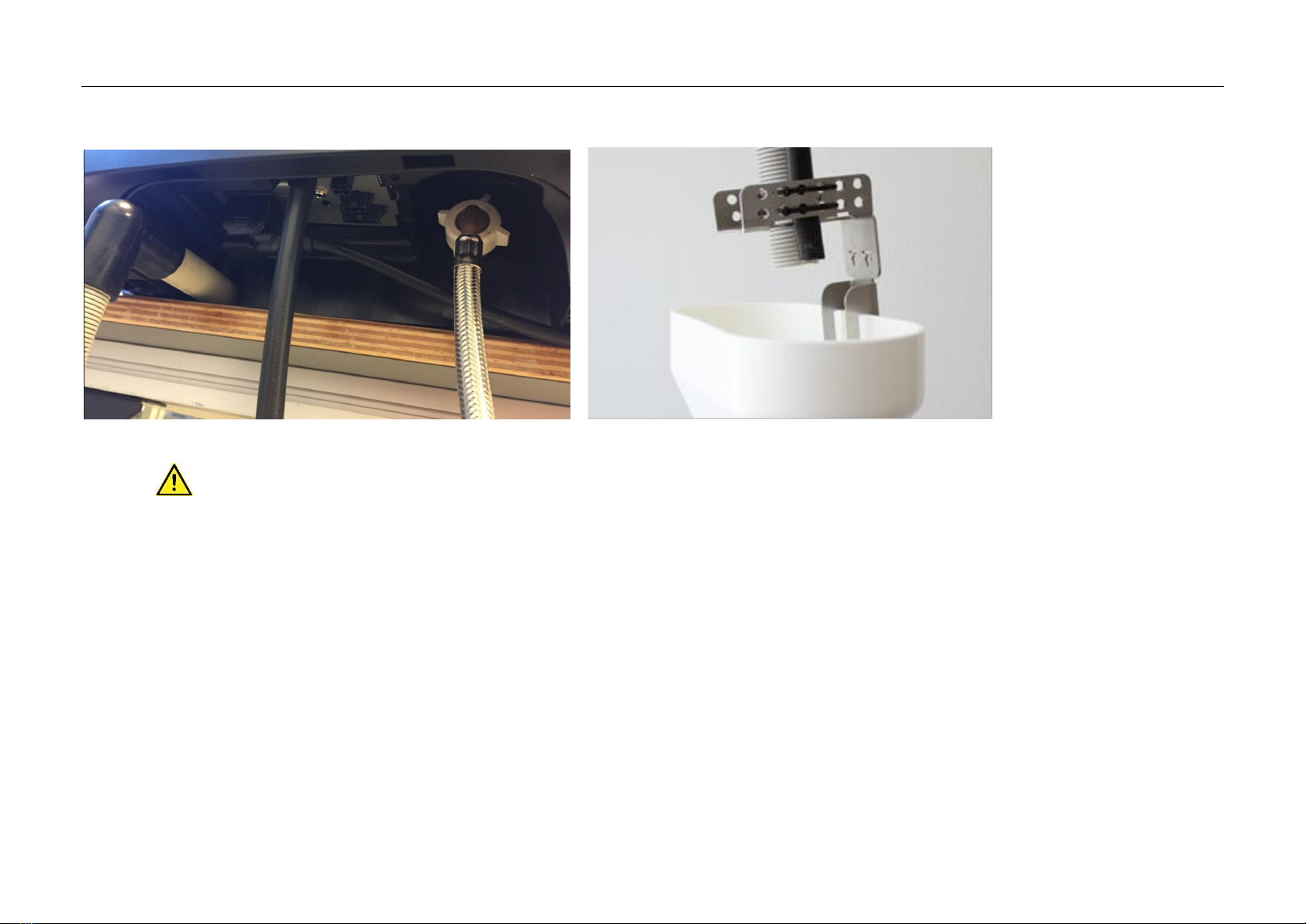
1.2 Hardware connection and preparatory work..........................................................................................................................................................................................................6
1.2.1 General activities.............................................................................................................................................................................................................................................................6
1.2.2 Recommended water filter...........................................................................................................................................................................................................................................8
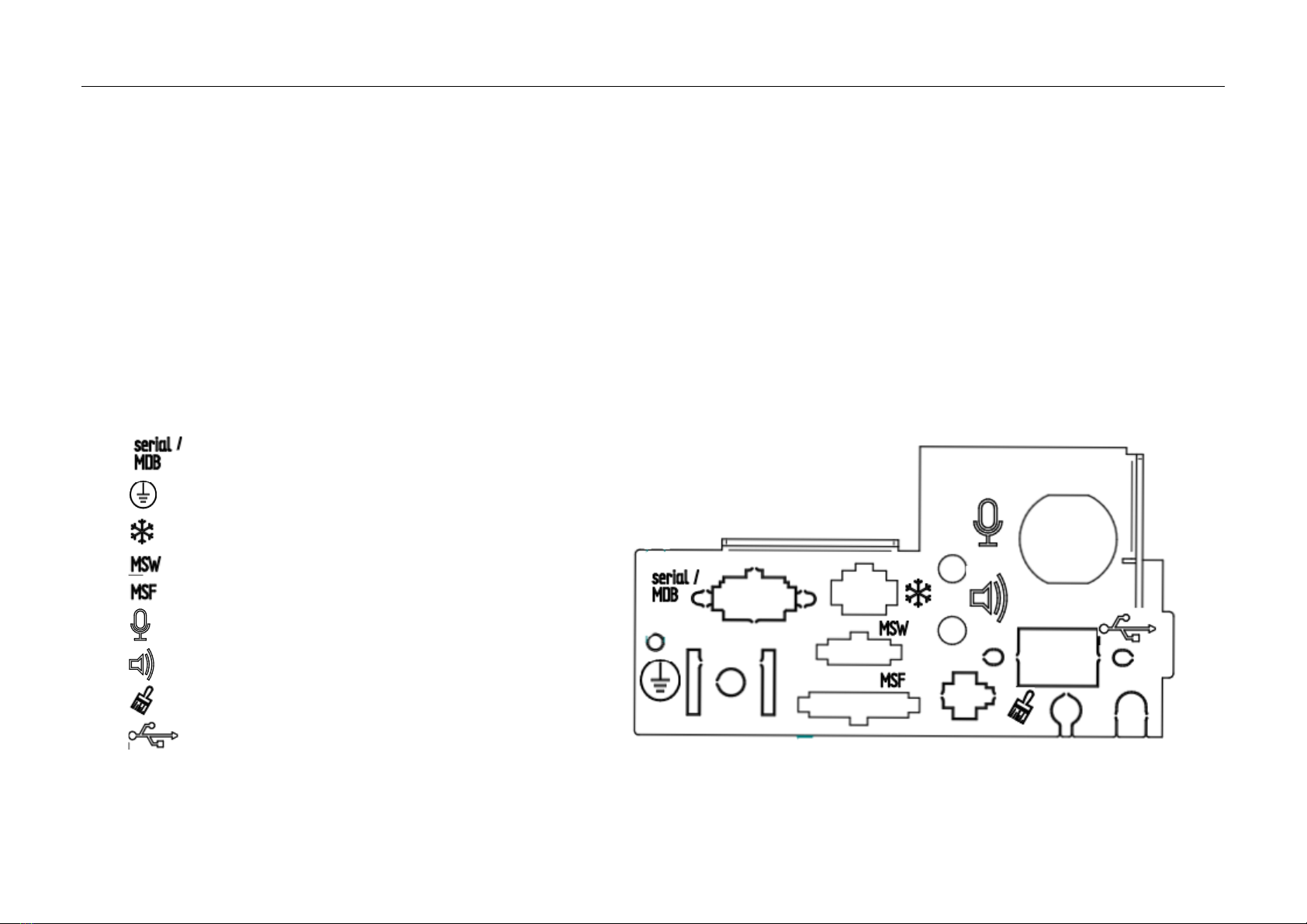
1.2.3 Interface plate for electrical connections................................................................................................................................................................................................................8
1.3 Initial commissioning.....................................................................................................................................................................................................................................................9
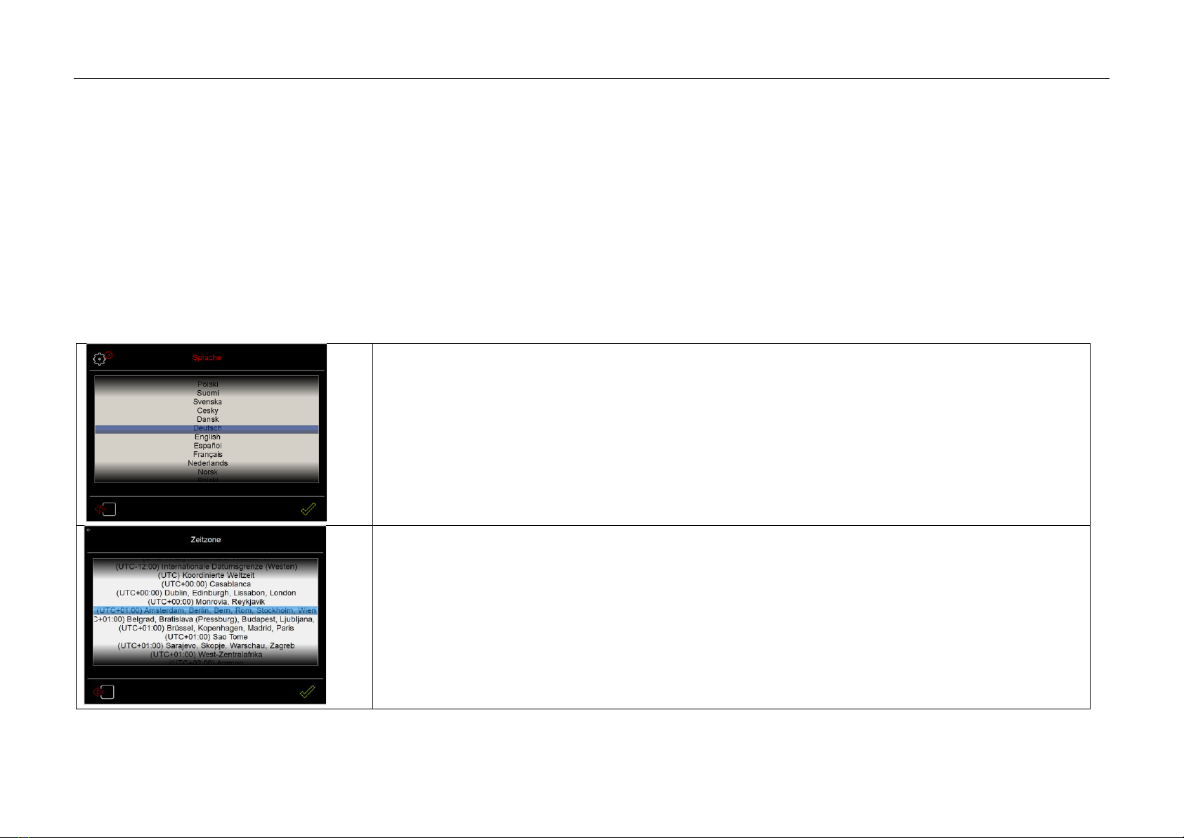
1.3.1 Goal of the Technician's Intro.....................................................................................................................................................................................................................................9
1.3.2 Workflow, Technician's Intro .......................................................................................................................................................................................................................................9
2Service........................................................................................................................................................................................................................................13
2.1 Brewer ..............................................................................................................................................................................................................................................................................13
2.2 Distance between angle sensor and brewer spindle (magnet) ........................................................................................................................................................................14
2.3 Espresso pump................................................................................................................................................................................................................................................................15
2.4 Grinders............................................................................................................................................................................................................................................................................16
2.4.1 Mechanical basic settings...........................................................................................................................................................................................................................................16
2.4.2 Using the electrical grinding degree setting on the grinder............................................................................................................................................................................16
2.4.3 Portioner calibration....................................................................................................................................................................................................................................................17
2.4.4 Grinder(s) idle current calibration............................................................................................................................................................................................................................18

Table of contents 5
2.4.5 Dynamic Coffee Assist advance settings................................................................................................................................................................................................................18
2.5 Powder portioner ..........................................................................................................................................................................................................................................................19
2.5.1 Portioner calibration for Choc / Topping...............................................................................................................................................................................................................19
2.6 Dynamic milk pump......................................................................................................................................................................................................................................................20
2.7 Power supply ..................................................................................................................................................................................................................................................................21
2.7.1 Use the test tool to check the power supply........................................................................................................................................................................................................22
2.8 Power stage ....................................................................................................................................................................................................................................................................23
2.8.1 CAN bus............................................................................................................................................................................................................................................................................24
2.9 Front panel......................................................................................................................................................................................................................................................................25
2.9.1 Panel Updater.................................................................................................................................................................................................................................................................26
2.10 Fan system.......................................................................................................................................................................................................................................................................31
2.11 Power Class .....................................................................................................................................................................................................................................................................33
2.12 Antifreeze /Transport preparation ...........................................................................................................................................................................................................................34
3Notes on piping diagrams .......................................................................................................................................................................................................35
4Maintenance .............................................................................................................................................................................................................................36
4.1 Maintenance concept –Overview of maintenance tasks..................................................................................................................................................................................36
4.2 Service maintenance 1 every 60,000 brewing cycles.........................................................................................................................................................................................37
4.3 Service Maintenance 2 - every 2 years...................................................................................................................................................................................................................38
4.4 Descaling..........................................................................................................................................................................................................................................................................39
5Special tools and aids ..............................................................................................................................................................................................................40

Installation and commissioning 6
1Installation and commissioning
1.1 Customer’s on-site connection requirements
Any necessary on-site preparatory work for electricity, water, and drainage connections at the customer‘s premises is to be arranged by the machine owner / operator.
The work must be carried out by authorized installation technicians in compliance with general, country-specific and local regulations.
The WMF Service engineers may only connect the coffee machine to existing prepared connection points.
WMF Service is neither authorized nor responsible for carrying out any work on-site prior to connection.
For details, see the planning information on the website www.wmf-coffeemachines.com.
Notes
-Electrically conductive counter surfaces must be earthed
-Unplug the mains plug before disconnecting the mains voltage across the cold appliance plug
1.2 Hardware connection and preparatory work
1.2.1 General activities
Place the coffee machine horizontally on the counter (width and depth); adjust feet where adjustable
Connect the water infeed
Water filter needed? If „Yes“–connect (for details, see the following chapter)
Connect the drain –use angle 33 2165 8000 from horizontal to vertical.

Installation and commissioning 7
Example, Dynamic Milk: all drains must be sloped.
Attach the drain tube and rinse hose to the elbow connector using cable ties
Attention:
To prevent back-contamination, the hoses MUST NOT make contact with the wastewater.
Two position arrows are inscribed on the elbow connector for reference.
Connect to the power supply
Switch on the coffee machine

Installation and commissioning 8
1.2.2 Recommended water filter
We generally recommend the use of a water filter.
Using the WMF coffee machine without a suitable water filter can cause damage (e.g. due to lime scale buildup).
Use a test kit that has been properly stored and has not exceeded its expiration date to test the overall and carbonate hardness of the line water (before the
water filter).
Enter the measured values in the WMF Aquatool app and install the water filter recommended for your water consumption and type of coffee machine.
Please note the variance in line water values for the filter capacity shown in the app. (plan for buffer)
1.2.3 Interface plate for electrical connections
The back of the machine has cut-outs for the following electrical connections:
Accounting via serial or MDB interface
Potential equalization
Cooler empty message / temperature
Mobile Station Waste (wastewater)
Mobile Station Fresh (fresh water tank)
Audio In
Audio Out
Detecting the cleaning agent
Network

Installation and commissioning 9
1.3 Initial commissioning
1.3.1 Goal of the Technician's Intro
A guided implementation of mandatory basic settings.
As simple a start-up of the coffee machine as possible with a high-quality beverage quality.
The aim is not to cover all setting options.
If for example the settings stored as defaults are changed in the "Operating options" menu or if the position of beverage buttons is changed, cup volumes are to be
changed, this must take place after the intro has concluded.
1.3.2 Workflow, Technician's Intro
Set and where necessary change the language.
Set and adjust the time zone as necessary.

Installation and commissioning 10
Set automatic summer/winter time.
Adjust time and date where necessary.
The prompt appears asking whether to carry out start-up or not.
When "Yes": next step
When „No“: machine is filled then heat up and is then ready for use

Installation and commissioning 11
Enter the technician PIN.
(Since some access to service menus is provided as part of the Technician's Intro; it is used to ensure that only
technicians use the start-up intro.)
A pure information text page follows.
In this way, the setting steps to be performed are explained in detail.

Installation and commissioning 12
If needed, adjust the machine configuration.
After processing and confirmation, a restart will be required.
The menu items are intended –as they partly build on top of each another- to be processed from top to bottom.
(The cooler is only present when it was previously selected in the machine configuration).
Menu items which were run through and processed are marked with a check.
The OK button appears once all menu items have been processed.
A concluding information text page appears.

Service 13
2Service
2.1 Brewer
The HD brewer is used in the WMF 5000 S+.
The brewer unit without grounds chute is available as a spare part. This brewing unit is also used in the following
machine models:
WMF 5000 S, WMF 8000 S+, WMF 9000 S+
Special case for FFC:
Illustration of spare HD brewer
Brewers for machines with Fresh Filtered Coffee (FFC) use a „Top portafilter“WITHOUT aperture.
This is indicated by a label on the brewing unit. When replacing the brewing unit, the top portafilter WITHOUT aperture
must also be replaced.
Top portafilter WITH aperture 33 2920 6000
Top portafilter WITHOUT aperture for FFC 33 2883 5000
Illustration of top portafilter
The technician can remove and install the brewer in just a few, easy steps.
1. Remove grounds container, drip tray
2. Unscrew the lock screw on the release lever
3. Pull the release lever on the brewer and pull the brewer forward to remove

Service 14
2.2 Distance between angle sensor and brewer spindle (magnet)
The "Brewer in place" status is detected by the angle sensor, which detects the magnet
installed at the upper end of the brewer spindle.
The distance between the angle sensor and the magnet on the brewer spindle must be
between 0.8 and 2.8 mm. This distance is checked during commissioning in the factory.
When it is too low, then spacers are installed to compensate for component tolerances.
When the brewer or brewer screen is replaced, the spacing distance must be checked:
Unscrew the angle sensors.
Leave the installed state as it is (with or without spacers).
Check spacing with gage.
If the gap is greater than 2.8 mm > then remove spacers.
If the gap is less than 0.8 mm > install spacing shim.
A set of spacers consisting of 2 plates of 0.5 mm and 1 mm thickness is available for
adjusting the spacing.
Item number 33 2908 1000
The set of spacers is included with a spare brewer drive.
Fig. Checking the distance Fig. Gage 33 2695 5000

Service 15
2.3 Espresso pump
The espresso pump used in the WMF 5000 S+ has a „balanced“pump head. The output pressure is
regulated to the pump pressure setting, regardless of the input pressure. The standard factory
setting is 7.5 bar.
The pump head is available as a separate spare part. When the pump head is replaced, make sure
than the alignment is correct. The pump connections must be at right angles to the pump motor
mounts.
Setting the pump pressure:
The setting screw on the espresso pump can be accessed via the brewer shaft.
The standard installed pressure sensor can be used for adjusting the pump pressure. The
service routine „Adjust espresso pump“displays the pump pressure on the screen.
Important notes for technicians / Note to customer
The espresso pump is NOT self-priming.
Risk of damage to the espresso pump when running empty.
The coffee machine must therefore have an upstream pressure on the line side of 0.2 bar. This means:
Under no circumstances must the coffee machine be operated with tank which DOES NOT HAVE a supply pump between it and the machine.

Service 16
2.4 Grinders
Right grinder The grinder on the right is pre-set to grinding degree 1, espresso grind.
This corresponds to a discharge rate of about 2.2 g/s, and a grain size distribution of about 470 μm.
Left and center grinder The center / left grinder is pre-set to grinding degree 5, creme grind.
This corresponds to a discharge rate of about 2.6 g/s, and a grain size distribution of about 640 μm.
Note: When the grinder disks or grinder have been replaced, reset the grinder counter.
Service > Service date > Grinder 1 grinder disk / Grinder 2 grinder disk > Confirm Maintenance
2.4.1 Mechanical basic settings
This setting is made with the grinder completely empty, without the adjustment motor, outside of the machine
Turn the disks together with the crown gear assembled until the disks are seated together and can no longer be
turned on the drive shaft by hand.
Adjust basic setting for grinding degree
The seam on the grinder outlet can be used as a visual guide here; see illustration.
Turn the top grinder disk to open it by 10 teeth, corresponding to grinding degree 1 - espresso grind
Turn the top grinder disk to open it by 18 teeth, corresponding to grinding degree 5 - crème grind
2.4.2 Using the electrical grinding degree setting on the grinder
Install the adjusting motor and place the grinder in the machine
Enter the mechanically grinding degree setting under Service > Machine data > Enter grinding degree setting
The software limits the range for the setting to prevent it from locking up
When needed see grinding degree using System > Set grinding degree > Grinding degree grinder 1 / Grinding degree grinder 2 nachstellen
Perform portioner calibration

Service 17
2.4.3 Portioner calibration
Coffee grinder actuation is time-controlled. In order to be able to enter the amount of ground coffee in grams in a recipe, a portioner
calibration is necessary. A portioner calibration determines the amount of ground coffee dispensed per second of running time. Based on this, the machine can
calculate
the running time needed for the amount of ground coffee programmed in the recipe.
A portioner calibration is needed, or must be repeated:
For a new machine during commissioning
When using a different type of coffee than was used for the last portioner calibration
After changing the grinding degree setting
After replacing the grinder disks
After opening or cleaning a grinder (during maintenance, for example)
Preconditions:
Bean hoppers must be half full
Grinder must be completely filled with fresh ground coffee
The grinder motor must be at operating temperature →Run 10 grinding cycles prior to starting calibration
In order to ensure that residual water does not falsify the calibration (up to 3 g of water can be present in the connecting hoses), proceed as follows:
Discard and do not use the ground coffee from the first portioner calibration
Afterward, remove the brewer and clean it, dry it, and reinstall it
Alternatively, a new or cleaned brewer can be used for the calibration
Also clean and dry the coffee grounds container (for machines with the „Grounds through counter“option, the coffee grounds container
must be closed in order to perform the calibration)
Measurement equipment / accessories needed:
Scale with a resolution of at least 0.1 g and accuracy of at least ±0.3 g
Other electronic equipment (such as mobile phones or laptops) can interfere with electronic scales - do not use the scale in the direct vicinity of other
electronic devices
The scale must be set on a flat, level surface
When weighing ground coffee, we always recommend transferring the ground coffee from the coffee grounds container into a tared paper cup or measuring
container in order to minimize measurement errors
Start the portioner calibration and follow the instructions on the display: Service > Service routines > Portioner calibration > Portioner 1/2

Service 18
2.4.4 Grinder(s) idle current calibration
In order to obtain correct notifications that the bean hopper is empty, a grinder idle current calibration can be performed for each grinder
Interrupt bean feeding →Lock or remove the hopper
Start the grinder idle current calibration and follow the instructions on the display
Service
>
Service routines
>
Idle current calibration
>
Portioner 1/2
The measured idle current is then automatically entered in the software
Restore the bean infeed
2.4.5 Dynamic Coffee Assist advance settings
With Dynamic Coffee Assist, beverages with espresso can be monitored and adjusted automatically.
The brewing flow must be set to 3 –5 ml/s for this.
Illustration shows the espresso component of the latte macchiato as
an example
1. Double espresso setting
1.1. Set default setting for Q stage to Q4 and use grinding degree seting to set grinding degree to -1
1.2. 3 Remove the test beverages and adjust the grinding degree from the grinding degree settings until reaching a brew flow of 3-5 ml/s
The brewing flow can be observed by pressing the Info button
1.3. If the brew flow cannot be reached, adjust the wet-pressing value slightly and re-test
1.4. Save beverage
2. Perform portioner calibration for the espresso grinder
3. Check the double espresso again–if necessary, correct the wet-pressing value or quality level
4. Single espresso setting
4.1. Change default setting for the Q stage to Q6
4.2. Remove 3 test beverages and adjust the wet pressing force until reaching a brew flow of 3-5 ml/s
4.3. Save beverage

Service 19
5. Apply the single and double espresso settings to beverages with espresso content
2.5 Powder portioner
2.5.1 Portioner calibration for Choc / Topping
Actuation of the powder portioner is time-controlled. In order to be able to enter the amount of powder in grams in a recipe, a portioner
calibration is necessary. A portioner calibration determines the amount of powder dispensed per second of running time. Based on this, the machine can calculate
the running time needed for the amount of powder programmed in the recipe.
A portioner calibration is needed, or must be repeated:
For a new machine during commissioning
When using a different type of powder than was used for the last portioner calibration
Preconditions:
Powder hopper must be half full
The metering screw must be completely filled with fresh powder
Measurement equipment / accessories needed:
Scale with a resolution of at least 0.1 g and accuracy of at least ±0.3 g
Other electronic equipment (such as mobile phones or laptops) can interfere with electronic scales - do not use the scale in the direct vicinity of other
electronic devices
The scale must be set on a flat, level surface
Measuring cup of at least 500 ml in volume
Start the portioner calibration and follow the instructions on the display: Service > Service routines > Portioner calibration > Portioner 3/3 left

Service 20
2.6 Dynamic milk pump
The ultrasonic sensor installed in the milk path monitors the milk pump performance and flow of the milk. The voltage of the pump motor can be corrected by up to
±5 % as needed. Correcting the pump power output results in a constant milk foam quality and dispensing temperature.
When the milk pump is recalibrated (Service > Service routines > Factory calibration of components > Dynamic milk system) the control range is reset to „0“
and the pump can once again be corrected by ±5 %.
Important note:
The milk pump calibration can be run only when the milk system is clean, with no deposits or screening. Otherwise there is a risk that the machine software will
attempt to compensate for screening in the milk system by increasing the milk pump power level. In this case, the pressure in the milk system would rise and increase
the risk that milk could be forced into the steam boiler.
A spare parts kit is available for the milk pump with stainless steel pump head (manufacturer’s designation DGA04) to enable replacing the plastic gears and the seals
in the pump head.
Important note:
To prevent damage to the shaft seal, the base body of the pump head (Pos. 1) should not be disassembled.
Remove the 4 socket head screws (Pos. 7) and the cover (Pos. 5)
Remove the spacer plate (Pos. 4), taking care not to remove the base body (Pos. 1) from
the motor
Replace the two gears (Pos. 2+3) and the two seals (Pos. 8)
When installing the cover and the socket head screws, tighten the screws in a cross
pattern with a tightening torque of 0.9 to 1.1 Nm
Other manuals for 5000S+
4
Table of contents
Other WMF Coffee Maker manuals

WMF
WMF 1300 S User manual

WMF
WMF Presto 1400 Series User manual

WMF
WMF Bistro easy 8300 User manual

WMF
WMF CASHMIRA User manual

WMF
WMF PROGRAMAT 4 7500 User manual

WMF
WMF Presto User manual

WMF
WMF CAFEMAT 3100 Series User manual

WMF
WMF WMF 1000 S User manual

WMF
WMF Coup AromaOne User manual

WMF
WMF Syline User manual