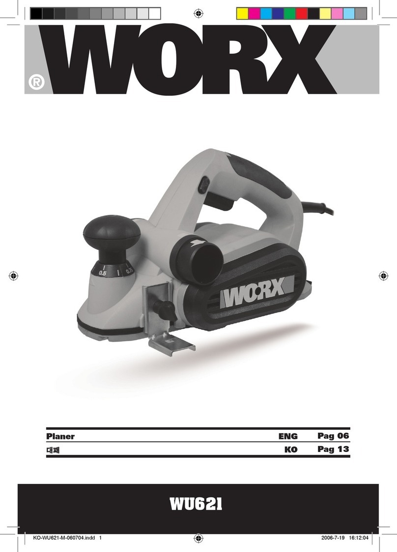
Worx WX622 User manual

P06
P12
P19
P26
P33
P40
P47
P54
P60
P66
P72
P78
P84
Planer
Hobel
Rabot
Pialla elettrica
Cepillo
Plaina
Schaafmachine
El-høvl
Höyläkone
Høvelmaskin
Slip
Planya
Πλάνη
EN
D
F
I
ES
PT
NL
DK
FIN
NOR
SV
TR
GR
WX622


82
2
10
15
7
8
11
6
9
14 11
54
2
1
3
16
17

82
2
10
15
7
8
11
6
9
14 11
54
2
1
3
16
17
A B C
D E F.1
F.2 F.3 F.4
G H I
J K

1. ON/OFF SWITCH
2. LOCK-OFF BUTTON
3. HAND GRIP AREAS
4. CHIP DEFLECTOR LEVER
5. DUST EXTRACTION
6. BASEPLATE STAND (SEE FIG E)
7. BLADE CLAMP (SEE FIG F)
8. BLADE (SEE FIG F) *
9. GUARD (SEE FIG F)
10. CUTTING DEPTH ADJUSTMENT
11. BELT COVER
12. SMALL PULLEY (SEE FIG G)
13. LARGE PULLEY (SEE FIG G)
14. BASEPLATE
15. V-GROOVE
16. DEPTH GAUGE(SEE FIG I) *
17. PARALLEL GUIDE(SEE FIG K) *
* Not all the accessories illustrated or described are included in standard delivery.
Planer EN
7 6 7 6

TECHNICAL DATA
ACCESSORIES
Only use reversible twin cutting blades that cannot be reground.
We recommend that you purchase your accessories from the same store that sold you the tool.
Use good quality accessories marked with a well-known brand name. Choose the type according
to the work you intend to undertake. Refer to the accessory packaging for further details. Store
personnel can assist you and offer advice.
NOISE AND VIBRATION DATA
A weighted sound pressure 84dB (A)
A weighted sound power 95dB (A)
Wear ear protection when sound pressure is over 85dB (A)
Typical weighted vibration 2.41m/s2
Spanner 1pc
Parallel guide 1pc
Rebate guide 1pc
Dust bag 1pc
Rated volts 220V-240V~50Hz/60Hz
Rated power 750W
Rated no load speed 16000/min
Cutting speed 32,000/min
Double insulation
Planing depth 0-2mm
Rebate capacity 0-8mm
Planing width 82mm
Machine weight 2.95Kg
7 6
Planer EN
7 6

ADDITIONAL SAFETY
POINTS FOR YOUR PLANER
1. Remove the plug from the socket before
carrying out any adjustment, servicing or
maintenance.
2. When an extension cable is required you
must ensure it has the correct ampere
rating for your power tool and is in a
safe electrical condition. Fully unwind
cable drum extensions to avoid potential
overheating.
3. Ensure your mains supply voltage is the
same as indicated on the rating plate.
4. Your tool is double insulated for additional
protection against a possible electrical
insulation failure within the tool.
5. Always check walls, floors and ceilings to
avoid hidden power cables and pipes.
6. After long working periods external metal
parts and accessories could be hot.
7. Wear eye protection when operating this
tool.
8. The base plate must always be held firmly
against the material being cut to reduce
vibration and blade jumping.
9. If possible, ensure the workpiece is firmly
clamped to prevent movement.
10. Your Planer is a hand held tool, do not
clamp your planer.
11. Before cutting, check the cutting line is free
of nails, screws, etc.
12. Never stop the cutting blade by applying
pressure to the blade.
13. Only withdraw the planer from the cut
when the blade has stopped moving.
14. Only use blades in excellent cutting
condition.
15. Do not put your fingers into the sawdust
exhaust outlet. Use a wooden stick to
unblock any material.
16. Wait for the cutter to stop before setting the
tool down, An exposed cutter may engage
the surface leading to possible loss of
control and serious injury.
17. Always wear a dust mask.
18. Hold tool by insulated gripping
surfaces when performing an
operation where the cutting tool may
contact hidden wiring. Contact with
a‘live’wire with also make exposed metal
parts of the tool‘live’and shock the operator
condition.
SYMBOLS
Read the manual
Warning
Double insulation
Wear eye protection
Wear ear protection
Wear dust mask
Planer EN
9 8 9 8

OPERATING INSTRUCTIONS
NOTE: Before using the tool, read the
instruction book carefully.
1. SAFETY ON/OFF SWITCH
Your switch is locked off to prevent accidental
starting. Depress the lock off button (2) then
on/off switch (1) and release lock off button
(2). Your switch is now on. To switch off just
release the on/off switch (See Fig A).
2. HAND GRIP AREAS
Always hold your planer firmly with both
hands when operating (See Fig B).
3. CUTTING DEPTH ADJUSTMENT
Smaller cutting depth of 0-2mm (Max. 3.0mm)
is best for most surface planning or rebating.
Rotate the cutting depth adjustment(4) to
set the required cutting depth on the scale
,Scale graduation = 0.125mm). The clockwise
rotation increases the planning depth; the
counterclockwise rotation reduces the planing
depth. (See Fig C)
4. CHIP DEFLECTION DIRECTION(See Fig
D)
Your tool is designed with left and right chip
deflector outlets for controlling the direction of
chips when working in confined areas. Before
starting the cut select left or right outlet by
rotating chip deflector lever accordingly.
5. BASEPLATE STAND
Uplift the rear of the planer, the baseplate
stand (6) can make the machine to be set
down directly and protect the cutting blades
from any damage and the blades from
damaging the surface. When planing, the
stand will be pushed away by the end of the
wood. Always check the stand is free to move
on the base plate (See Fig E).
6. BLADE FITTING AND CHANGING
WARNING: Remove power cord
from the socket before carrying out
any adjustments or changing blades.
The blade has two cutting edges, which can
be reversed. When replacing or reversing the
plane blades, the guide groove guarantees
constant height adjustment.
NOTE: Dull and worn blade cannot be
reground and must be replaced.
Remove the plug from the mains socket.
Using the Socket spanner provided loosen the
3 bolts approximately 1/2 rotation counter-
clockwise. Holding the blade clamp (7) in
position, using a piece of wood slides the
blade (8) out of the blade clamp (7) to remove
the blade from the blade clamp(See FigF).
NOTE: there is no need to remove the
blade clamp (7) as this can change the
factory settings for cutting blade height
control. Before reinserting a new or reverse
blade, always clean both the blade and the
blade seat if dirty. Slide the blade into the
blade clamp in the correct orientation. Check
the blade is equal with the clamp. When
tightening the screws ensure the correct
tightening sequence(See Fig F). Before
starting, rotate by hand to check the roller is
free to rotate.
Rotate the blade head by a further 180o and
repeat the procedure disassembling the
second plane blade.
7. REPLACING A DRIVE BELT
WARNING: 1. Remove the plug from
the socket before carrying out any
adjustment, servicing or maintenance.
2. The cutting blades will be turning and
may cause injury.
Loosen screw and remove belt cover (11),
remove worn drive belt from large pulley (13)
and small pulley (12) and clean them. lace
the new drive belt on the top of pinion and
turning it manually, press it on the large pulley
(13) (See Fig G).Make sure the drive belt runs
exactly along the length grooves of the pinion
and the pulley.
NOTE: Place the belt cover (11) back on
top and tighten it with screw.
8. FITTING A DUST BAG
This accessory can be fitted by sliding the dust
bag inlet over the planer dust extraction (5) as
far as possible. The dust bag will reduce the
efficiency of the exhaust system and the bag
must be emptied frequently to maintain the
efficiency. To empty, open the zip on the rear
9 8
Planer EN
9 8

of the dust bag.
NOTE: This accessory can be used for
smaller jobs.
9. EXTERNAL DUST EXTRACTION
The dust extraction (5) is best connected to a
suitable external dust extraction machine e.g.
vacuum cleaner.
WORKING HINTS FOR YOUR
PLANER
WARNING: Danger of kickback! Apply
the machine to the work piece only
when switched on.
1. STANDARD SURFACE PLANING
Set the desired cutting depth. Position the
front part of the base plate flat onto the work
surface. Switch the machine on and push your
planer forward and it will start cutting, always
maintain all of the base plate flat on the work
surface to prevent the cutting blade jumping.
Move the plane evenly over the work surface.
For most applications 0-3mm max cutting
depth will produce a good surface finish. It is
best to use small depths of cut and repeat the
planing process.
2. EDGE CHAMFERING
Using the V-groove in the base plate (15) you
can make a chamfer on the work piece edge
(See Fig H). Guide the planer along the edge
and maintain a constant angle and force to
produce a good finish. You can control the
angle of the chamfer with your hands. Make a
test chamfer on a scrap piece of wood. Ensure
your work piece is clamped and supported
near the edge.
3. REBATING (SEE FIG I, J, K)
You use the Rebate Depth Gauge (16) and
the Rebate Parallel Guide (17) accessories
(supplied with your tool). Fit these accessories
to your planer.
Set the required rebate depth using the scale
and the mark on the planer housing next to
the scale.
Set the required rebate width stop on the
parallel guide (17) using the locking screw and
adjust the required rebating width (max 82
mm). Tighten locking screw.
Set the parallel guide (17) using the locking
screw on the planner housing.
Adjust the desired rebating depth with the
rebating depth gauge (16) accordingly (max
24mm) .Plane as often as necessary to achieve
the desired rebating depth. Make sure the
plane is guided with a lateral supporting
pressure.
MAINTENANCE
Remove the plug from the socket before
carrying out any adjustment, servicing or
maintenance.
Your power tool requires no additional
lubrication or maintenance. There are no user
serviceable parts in your power tool. Never
use water or chemical cleaners to clean your
power tool. Wipe clean with a dry cloth.
Always store your power tool in a dry place.
Keep the motor ventilation slots clean. Keep
all working controls free of dust.
If the supply cord is damaged, it must be
replaced by the manufacturer, its service
agent or similarly qualified persons in order to
avoid a hazard.
ENVIRONMENTAL
PROTECTION
Waste electrical products should not
be disposed of with household waste.
Please recycle where facilities exist.
Check with your local authorities or retailer for
recycling advice.
Planer EN
11 10 11 10

PLUG REPLACEMENT (UK &
IRELAND ONLY)
If you need to replace the fitted plug then
follow the instructions below.
IMPORTANT
The wires in the mains lead are colored in
accordance with the following code:
BLUE =NEUTRAL
Brown = Live
As the colors of the wires in the mains lead of
this appliance may not correspond with the
colored markings identifying the terminals
in your plug, proceed as follows. The wire
which is colored blue must be connected to
the terminal which is marked with N. The wire
which is colored brown must be connected to
the terminal which is marked with L.
WARNING: Never connect live or neutral
wires to the earth terminal of the plug. Only
fit an approved 13ABS1363/A plug and the
correct rated fuse.
NOTE: If a moulded plug is fitted and has to
be removed take great care in disposing of the
plug and severed cable, it must be destroyed
to prevent engaging into a socket.
DECLARATION OF
CONFORMITY
We,
POSITEC Germany GmbH
Neuer Höltigbaum 6
22143 Hamburg
Declare that the product,
Description
WORX Planer
Type
WX622
Complies with the following directives,
EC Machinery directive
98/37/EC
EC Low voltage directive
2006/95/EC
EC Electromagnetic compatibility directive
2004/108/EC
Standards conform to
EN 55014-1
EN 55014-2
EN 61000-3-2
EN 61000-3-3
EN 60745-1
EN 60745-2-14
2006/01/01
Jacky Zhou
POSITEC Quality Manager
Connect
Blue to N
(neutral)
Outer sleeve
firmly clampedCable grip
Brown L (live)
13 Amp fuse approved
to BS1362
11 10
Planer EN
11 10

1. EIN-/AUSSCHALTER
2. ENTRIEGELUNGSSCHALTER
3. HANDGRIFF
4. SPAN-ABLENKUNGSHEBEL
5. STAUBAUSWURF
6. GRUNDPLATTENFUSS (SIEHE E)
7. KLINGENBEFESTIGUNG (SIEHE F)
8. KLINGE (SIEHE F) *
9. SCHUTZ (SIEHE F)
10. HOBELTIEFE-EINSTELLUNG
11. ANTRIEBSABDECKUNG
12. KLEINE SCHEIBE (SIEHE G)
13. GROSSE ROLLE (SIEHE G)
14. GRUNDPLATTE
15. V-NUT
16. TIEFENMESSER (SIEHE I) *
17. PARALLELE FÜHRUNG(SIEHE K) *
* Abgebildetes oder beschriebenes Zubehör gehört teilweise nicht zum Lieferumfang.
Hobel D
13 12 13 12

ZUBEHÖRTEIL
Umschaltbare Doppelausschnitblätter nur benutzen, die nicht nachgeschliffen werden
können.
Wir empfehlen Ihnen, sämtliche Zubehörteile beim selben Fachhändler zu beziehen, bei dem
Sie auch Ihr Elektrowerkzeug gekauft haben. Verwenden Sie nur hochwertige Zubehörteile von
namhaften Herstellern. Die Güteklasse muss entsprechend der Anwendung gewählt werden.
Weitere Informationen finden Sie auf der Verpackung der Zubehörteile. Auch Ihr Fachhändler
berät Sie gerne.
Spanner 1Stück
Parallele Führung 1Stück
Falztiefenanschlag 1Stück
Staubbeutel 1Stück
TECHNISCHE DATEN
LÄRMPEGEL UND VIBRATIONEN
Gewichteter Schalldruck 84dB (A)
Gewichtete Schallleistung 95dB (A)
Tragen Sie bei einem Schalldruck über 85 dB(A) einen Gehörschutz
Typischer gewichteter Vibrationswert 2.41m/s2
Nennspannung 220V-240V~50Hz/60Hz
Nennleistung 750W
Leerlaufnenndrehzahl 16000/min
Schnittgeschwindigkeit 32,000/min
Zweifach isoliert
Hobeltiefe 0-2mm
Falztiefe 0-8mm
Hobelbreite 82mm
Gewicht 2.95Kg
13 12
Hobel D
13 12

ZUSÄTZLICHE
SICHERHEITSMASSNAHMEN
FÜR IHREN HOBEL
1. Ziehen Sie den Stecker aus der Steckdose,
ehe Sie Einstellungsänderungen,
Reparatur- oder Wartungsarbeiten
durchführen.
2. Falls ein Verlängerungskabel erforderlich
ist, verwenden Sie ein funktionstüchtiges,
zugelassenes Verlängerungskabel, das für
die Leistung des Werkzeugs ausreichend
ist.
3. Kontrollieren Sie, ob die Netzspannung
der auf dem Typenschild angegebenen
Spannung entspricht.
4. Ihr Werkzeug ist schutzisoliert. Bei einem
etwaigen internen Kurzschluss sind Sie
sicher vor einem elektrischen Schlag
geschützt.
5. Prüfen Sie vor dem Arbeiten in Wänden
und Decken den genauen Verlauf von
Stromkabeln oder Rohrleitungen.
6. Nach längerem Gebrauch können
zugängliche Metall- und Zubehörteile sehr
heiß sein.
7. Tragen Sie beim Arbeiten mit diesem
Werkzeug eine Schutzbrille.
8. Die Grundplatte muss stets fest gegen das
zu schneidende Material gedrückt werden,
um Vibrationen und ein Springen oder
Brechen des Sägeblatts zu verhindern.
9. Sorgen Sie nach Möglichkeit dafür, dass
das Werkstück sicher befestigt ist und sich
nicht bewegen kann.
10. Ihr Hobel ist ein Handwerkzeug, nicht
stationär gebrauchen.
11. Entfernen Sie vor Beginn des Sägens
alle Nägel, Metallteile usw. aus dem
Arbeitsbereich.
12. Versuchen Sie niemals, die Säge durch
Drücken gegen die Seite des Blatts zu
stoppen.
13. Ziehen Sie das Blatt erst aus dem
Werkstück, wenn es sich nicht mehr
bewegt.
14. Verwenden Sie nur einwandfreie Blätter.
15. Finger nicht in den Staubauswurf stecken.
Verwenden Sie einen Holzstock, um
Verstopfungen zu entfernen.
16. Warten Sie, bis die Klinge zum Stillstand
gekommen ist, bevor Sie das Werkzeug
hinstellen. Das Messer kann ansonsten
in die Oberfläche greifen, das Werkzeug
außer Kontrolle bringen und damit schwere
Verletzungen verursachen.
17. Immer Staubmaske tragen.
18. Halten Sie das Werkzeug an den
isolierten Griffen, wenn die Gefahr
besteht, dass Sie beim Arbeiten in
Wänden, Decken usw. verborgene
Leitungen oder das Netzkabel
berühren könnten. Metallteile am
Werkzeug, die mit stromführenden
Drähten in Berührung kommen, werden
selbst stromführend und können der
Bedienperson einen elektrischen Schlag
versetzen.
Hobel D
15 14 15 14

SYMBOLE HINWEISE ZUM BETRIEB
HINWEIS: Lesen Sie das Handbuch vor
Inbetriebnahme des Werkzeuges sorgfältig
durch.
1. SICHERHEITS EIN-/AUSSCHALTER
Der Schalter ist gesichert, um ein
versehentliches Einschalten zu vermeiden.
Drücken Sie den Entriegelungsschalter (2),
dann den Ein-/Ausschalter (1) und lassen Sie
den Entriegelungsschalter (2) los. Das Gerät
ist eingeschaltet. Lassen Sie zum Ausschalten
den Ein-/Ausschalter los (Siehe A).
2. HANDGRIFFBEREICHE
Halten Sie die Hobelmaschine beim Betrieb
stets fest mit zwei Händen (Siehe B).
3. HOBELTIEFE-EINSTELLUNG
Eine geringe Hobeltiefe von 0-2 mm
(max. 3,0 mm) ist ideal zum Hobeln oder
Falzen der meisten Oberflächen. Drehen
Sie die Hobeltiefe-Einstellung (4) auf die
gewünschte Einstellung (Anzeigestufung
= 0,125 mm). Drehen Sie im Uhrzeigersinn
um die Hobeltiefe zu erhöhen, gegen den
Uhrzeigersinn um sie zu verringern (Siehe C).
4. SPAN-ABLENKUNGSRICHTUNG(Siehe
D)
Ihr Werkzeug ist links und rechts mit Span-
Ablenkungsausgängen ausgestattet, die bei
der Arbeit in beschränkten Bereichen die
Richtung von Spänen steuern. Bevor Sie
den Schnitt ansetzen, wählen Sie den linken
oder rechten Ausgang, indem Sie den Span-
Ablenkungshebel entsprechend drehen.
5. GRUNDPLATTENFUSS
Heben Sie das hintere Ende des Hobels an,
mithilfe des Grundplattenfußes (6) können Sie
das Gerät direkt auf das Werkstück setzten und
damit Hobelmesser und Werkstückoberfläche
vor Beschädigungen schützen. Beim Hobeln
wird der Fuß durch das Ende des Werkstücks
weggestoßen. Prüfen Sie, dass der Fuß stets
frei beweglich ist (Siehe E).
Bedienungsanleitung lesen
Warnung
Schutzisolation
Schutzmaske tragen
Gehörschutz tragen
Schutzmaske tragen
15 14
Hobel D
15 14

6. MESSER EINSETZEN UND
AUSTAUSCHEN
WARNUNG: Ziehen Sie den
Netzstecker aus der Steckdose,
bevor Sie Einstellungen am Messer
vornehmen bzw. das Messer wechseln.
Das Messer hat zwei austauschbare
Schneidseiten. Beim Wechseln oder
Umdrehen der Messer sorgt die Führungsfuge
für konstante Höheneinstellung.
HINWEIS: Stumpfe und abgenutzte
Messer können nicht geschliffen werden
und müssen ausgewechselt werden.
Ziehen Sie den Netzstecker aus der
Steckdose. Lösen Sie die drei Bolzen mithilfe
des Spanners, ca. 1/2 Drehung gegen den
Uhrzeigersinn (Siehe F). Halten Sie die
Klingenbefestigung (7) in Position und
schieben Sie die Klinge (8) mithilfe eines
Holzstücks aus der Klingenbefestigung (7)
(Siehe E). HINWEIS: Dabei sollte die
Klingenbefestigung (7) nicht entfernt
werden, dies kann zu Änderungen der
Höheneinstellung führen. Reinigen Sie ggf.
Messer und Klingenbefestigung, bevor Sie
ein neues Messer einsetzen bzw. das Messer
umdrehen. Schieben Sie das Messer in
korrekter Ausrichtung in die Klingenhalterung.
Prüfen Sie, dass Messer und Klingenhalterung
bündig sind. Achten Sie beim Festziehen der
Schrauben auf die korrekte Reihenfolge (Siehe
F). Bevor Sie das Gerät starten, drehen Sie das
Messer zur Überprüfung per Hand.
Drehen Sie das Messer weitere 180o und
wiederholen Sie den Vorgang für die zweite
Messerhalterung.
7. ANTRIEBSRIEMEN AUSTAUSCHEN
WARNUNG: 1. Ziehen Sie vor
jeglichen Einstellungen, Wartungs-
oder Pflegearbeiten immer den
Netzstecker aus der Steckdose.
2. Die Hobelmesser können sich drehen
und Verletzungen verursachen.
Lösen Sie die Schrauben und nehmen Sie
die Antriebsabdeckung (11) ab. Entfernen Sie
den abgenutzten Antriebsriemen von der
großen Rolle (13) und dem Antriebsrad (12)
und reinigen Sie diese. Legen Sie einen neuen
Antriebsriemen auf das Antriebsrad und
ziehen Sie ihn über die große Rolle (13) (Siehe
G). Prüfen Sie, dass der Antriebsriemen genau
über die Einkerbungen von Antriebsrad und
großer Rolle läuft.
HINWEIS: Setzen Sie die
Antriebsabdeckung (11) wieder auf und
ziehen Sie die Schrauben fest.
8. STAUBBEUTEL BEFESTIGEN
Dieses Zubehörteil kann befestigt werden,
indem Sie den Staubbeuteleinlass so weit
wie möglich über den Staubauswurf (5)
ziehen. Der Staubbeutel reduziert die Effizienz
des Staubauswurfs und muss regelmäßig
geleert werden. Öffnen Sie zum Leeren
den Reißverschluss an der Hinterseite des
Staubbeutels.
HINWEIS: Dieses Zubehör kann für
kleinere Arbeiten verwendet werden.
9. EXTERNER STAUBAUFFANG
Für optimale Leistung kann der
Staubauswurf (5) an einen passenden
externen Staubauffang, z.B. Staubsauger,
angeschlossen werden.
ARBEITSTIPPS FÜR IHREN
HOBEL
WARNUNG: Gefahr von Rückschlag!
Setzen Sie das Gerät nur in laufendem
Zustand auf das Werkstück.
1. NORMALES HOBELN
Stellen Sie die gewünschte Hobeltiefe ein.
Setzen Sie die Vorderseite der Grundplatte
flach auf das Werkstück. Schalten Sie das
Gerät ein und schieben Sie den Hobel nach
vorne. Der Hobelvorgang beginnt. Halten Sie
die gesamte Grundplatte stets flach auf dem
Werkstück, um ein Springen der Hobelmesser
zu vermeiden. Schieben Sie den Hobel
gleichmäßig über das Werkstück. Für die
meisten Arbeiten reicht eine Hobeltiefe von 0 –
3 mm, um gute Arbeitsergebnisse zu erzielen.
Für beste Resultate sollten Sie geringe
Hobeltiefen und wiederholte Arbeitsgänge
verwenden.
Hobel D
17 16 17 16

2. ECKENANSCHRÄGUNG
Mithilfe der V-Nut der Bodenplatte (15)
können Sie die Ecken des Werkstücks
anschrägen (Siehe H). Schieben Sie den
Hobel in gleichmäßigem Winkel entlang der
Werkstückkante. Kontrollieren Sie dabei den
Winkel des Gerätes zum Werkstück mit Ihren
Händen. Testen Sie diesen Vorgang zunächst
an einem Abfallstück. Achten Sie darauf, dass
das Werkstück ordnungsgemäß befestigt ist.
3. FALZEN(Siehe I, J,K)
Verwenden Sie die Falztiefen-Anzeige (16) und
Falz-Parallelführung (17) (im Lieferumfang
enthalten). Befestigen Sie dieses Zubehör an
Ihrem Hobel.
Stellen Sie die gewünschte Falztiefe mithilfe
der Anzeige und der Markierung auf dem
Hobelgehäuse neben der Anzeige ein.
Stellen Sie den gewünschten Nut-
Tiefenanschlag am Parallelanschlag (17) mit
Hilfe der Feststellschraube ein und passen Sie
die erforderliche Nutbreite (max. 82 mm) an.
Ziehen Sie die Feststellschraube an.
Stellen Sie den Parallelanschlag (17) mit Hilfe
der Feststellschraube am Gerätegehäuse ein.
Ziehen Sie die Feststellschraube fest. Stellen
Sie die gewünschte Falztiefe (max. 24mm)
mithilfe der Falztiefen-Anzeige (16) ein
.Wiederholen Sie den Falzvorgang, bis die
gewünschte Falztiefe erreicht ist. Führen Sie
den Hobel mit seitlichem Druck über das
Werkstück.
WARTUNG
Ziehen Sie grundsätzlich den Netzstecker,
bevor Sie Einstell-, Reparatur- oder
Wartungstätigkeiten ausführen.
Es enthält keine Teile, die Sie warten müssen.
Reinigen Sie Ihr Werkzeug niemals mit Wasser
oder chemischen Reinigungsmitteln. Wischen
Sie es mit einem trockenen Tuch sauber.
Lagern Sie Ihr Werkzeug immer an einem
trockenen Platz. Halten Sie die Lüftungsschlitze
sauber. Gelegentlich sind durch die
Lüftungsschlitze hindurch Funken zu sehen.
Falls das Netzkabel beschädigt sein sollte,
muss es vom Hersteller, einem seiner Service-
Beauftragten oder einer ähnlich qualifizierten
Person instandgesetzt werden, damit es nicht
zu Gefährdungen kommt.
UMWELTSCHUTZ
Elektroprodukte dürfen nicht mit dem
normalen Haushaltsmüll entsorgt
werden, sondern sollten nach
Möglichkeit zu einer Recyclingstelle gebracht
werden. Ihre zuständigen Behörden oder
Ihr Fachhändler geben Ihnen hierzu gerne
Auskunft.
17 16
Hobel D
17 16

KONFORMITÄTSERKLÄRUNG
Wir,
POSITEC Germany GmbH
Neuer Höltigbaum 6
22143 Hamburg
Erklären hiermit, dass unser Produkt
Beschreibung
WORX Hobel
Typ
WX622
Den Bestimmungen der folgenden Richtlinien
entspricht:
EC Maschinenrichtlinie
98/37/EC
EC Niederspannungsrichtlinie
2006/95/EC
EC EMV-Richtlinie
2004/108/EC
Werte nach
EN 55014-1
EN 55014-2
EN 61000-3-2
EN 61000-3-3
EN 60745-1
EN 60745-2-14
2006/01/01
Jacky Zhou
POSITEC Qualitätsleiter
Hobel D
19 18 19 18

1. INTERRUPTEUR MARCHE/ARRET
2. INTERRUPTEUR DE VEROUILLAGE
3. LA POIGNEE
4. LEVIER DU DÉFLECTEUR DE COPEAUX
5. BUSE D’ASPIRATION
6. SUPPORT DE LA PLAQUE DE BASE( VOIR E)
7. COLLIER DES SERRAGE DE LAMES( VOIR F)
8. LAME( VOIR F) *
9. GARDE (VOIR F)
10. AJUSTEMENT DE PROFONDEUR DE COUPE
11. REVETEMENT DE LA COURROIE
12. PETITE POULIE (VOIR G)
13. GRANDE POULLIE( VOIR G)
14. PLAQUE DE BASE
15. SILLON EN V
16. JAUGE DE PROFONDEUR( VOIR I) *
17. GUIDE PARALLÈLE( VOIR K) *
* Les accessoires reproduits ou décrits ne sont pas tous compris dans les fournitures.
19 18 19 18
Rabot F

ACCESSOIRES
N’utiliser que des lames de coupe doubles réversibles qui ne peuvent pas être
aiguisées.
Nous recommandons d’acheter tous les accessoires dans le magasin où l’outil a été acheté.
Utiliser des accessoires de bonne qualité et de marque. Se reporter au chapitre ’’ Conseils
d’utilisation ’’ dans le manuel ou à l’emballage de l’outil pour de plus amples informations. Le
personnel du magasin peut également apporter aide et conseils.
Clé à douille 1pièce
Guide parallèle 1pièce
Guide de rabotage 1pièce
Sac à poussière 1pièce
FICHE TECHNIQUE
DONNEES SUR LE BRUIT ET LES VIBRATIONS
Niveau de pression sonore mesurée 84dB (A)
Niveau de puissance sonore mesurée 95dB (A)
Porter un casque antibruit si la pression sonore est supérieure à 85dB (A)
Valeur de vibration mesurée 2.41m/s2
Tension nominale 220V-240V~50Hz/60Hz
Puissance nominale 750W
Vitesse a vide nominale 16000/min
Vitesse de coupe 32,000/min
Double isolation
Profondeur de rabotage 0-2mm
Capacité de feuillure 0-8mm
Largeur de rabotage 82mm
Poids 2.95Kg
Rabot F
21 20 21 20
Table of contents
Languages:
Other Worx Planer manuals
Popular Planer manuals by other brands

Ryobi
Ryobi RPN780 Original instructions

King Industrial
King Industrial KC-530FXR instruction manual

AEG
AEG BHO 18 Original instructions

Powermatic
Powermatic 15HH Operating instructions and parts manual

Scheppach
Scheppach HMS1070 Translation from the original instruction manual

King Industrial
King Industrial KC-235PM Service manual